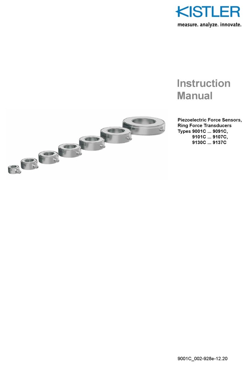
Kistler 9327C User manual

Instruction
Manual
3-Component Force
Link
Type 9327C
9327C_002-477e-05.10

Instruction
Manual
3-Component Force
Link
Type 9327C
9327C_002-477e-05.10
Fz
Fx
Fy

Foreword
9327C_002-477e-05.10 Page 1
Foreword
Thank you for choosing a Kistler quality product character-
ized by technical innovation, precision and long life.
Information in this document is subject to change without
notice. Kistler reserves the right to change or improve its
products and make changes in the content without obliga-
tion to notify any person or organization of such changes
or improvements.
©2010, Kistler Group. All rights reserved. Except as ex-
pressly provided herein, no part of this manual may be re-
produced for any purpose without the express prior written
consent of Kistler Group.

3-Component Force Link, Type 9327C
Page 2 9327C_002-477e-05.10
Content
1. Introduction ................................................................................................................................... 4
2. Important Notes............................................................................................................................. 5
2.1 For Your Safety .................................................................................................................... 5
2.2 Unpacking............................................................................................................................ 6
2.3 Notes on Handling the Instrument ....................................................................................... 6
2.4 Tips on the Use of this Instruction Manual ........................................................................... 7
2.5 What Happens in the Event of Changes? ............................................................................. 7
3. General Description of the Instrument........................................................................................... 8
3.1 What is the Purpose of a 3-Component Force Link? ............................................................ 8
3.2 Functional Principle ............................................................................................................10
4. Assembly, Installation and Initial Start-Up .................................................................................. 11
4.1 Important Notes.................................................................................................................11
4.2 Mounting of 3-Component Force Link............................................................................... 11
5. Measuring Range/Introduction of Force ...................................................................................... 13
5.1 3-Component Force Measurement Using a Dynamometer ................................................ 13
5.2 6-Component Force Measurement Using a Dynamometer ................................................ 15
5.3 3-Component Force Measurement Using a Single Force Sensor......................................... 16
5.4 Measuring System with 3-Component Force Link .............................................................. 21
5.5 Measuring System with four 3-Component Force Links (Dynamometer)............................ 21
6. Operation..................................................................................................................................... 22
6.1 Range Selection.................................................................................................................. 22
6.2 Measuring Small Force Changes......................................................................................... 22
6.3 Useful Frequency Range..................................................................................................... 24
6.4 Piezoelectric Force Measurement ....................................................................................... 26
6.5 Hints for Better Measuring Results ..................................................................................... 29
6.6 Polarity of the Measuring Signal......................................................................................... 29
7. Maintenance ................................................................................................................................30
7.1 Recalibrating the Instrument .............................................................................................. 30
7.2 Maintenance Work ............................................................................................................ 30
8. Rectifying Faults .......................................................................................................................... 32
8.1 Troubleshooting .................................................................................................................32
8.2 If Your Sensor is Defective.................................................................................................. 32
9. Technical Data ............................................................................................................................. 33
9.1 3-Component Force Link Type 9327C ............................................................................... 33
9.2 Dimensions 3-Component Force Link Type 9327C............................................................. 34
9.3 Optional Accessories .......................................................................................................... 35

Content
9327C_002-477e-05.10 Page 3
10. Annex ...........................................................................................................................................38
10.1 Glossary ..............................................................................................................................38
10.2 Measurement Uncertainty ..................................................................................................41
10.3 Linearity..............................................................................................................................42
10.4 Frequency Range ................................................................................................................44
10.5 Influence of Temperature....................................................................................................45
10.6 Index ..................................................................................................................................47
Total pages 47

3-Component Force Link, Type 9327C
Page 4 9327C_002-477e-05.10
1. Introduction
Please take the time to thoroughly read this instruction
manual. It will help you with the installation, maintenance,
and use of this product.
To the extent permitted by law Kistler does not accept any
liability if this instruction manual is not followed or prod-
ucts other than those listed under Accessories are used.
Kistler offers a wide range of products for use in measuring
technology:
Piezoelectric sensors for measuring force, torque, strain,
pressure, acceleration, shock, vibration and acoustic-
emission
Strain gage sensor systems for measuring force and tor-
que
Piezoresistive pressure sensors and transmitters
Signal conditioners, indicators and calibrators
Electronic control and monitoring systems as well as
software for specific measurement applications
Data transmission modules (telemetry)
Kistler also develops and produces measuring solutions for
the application fields engines, vehicles, manufacturing,
plastics and biomechanics.
Our product and application brochures will provide you
with an overview of our product range. Detailed data
sheets are available for almost all products.
If you need additional help beyond what can be found ei-
ther on-line or in this manual, please contact Kistler's ex-
tensive support organization.

Important Notes
9327C_002-477e-05.10 Page 5
2. Important Notes
It is essential for you to study the following information,
compliance with which is for your personal safety during
the work and will ensure long, fault-free operation of the
instrument.
2.1 For Your Safety
This instrument has been thoroughly tested and has left
the factory in a perfectly safe condition. In order to
maintain this condition and to ensure hazard-free oper-
ation, the user must comply with the information and
warning notes contained in these operating instructions.
The sensor must be installed, operated and maintained
only by persons who are familiar with the instrument
and are adequately qualified for the work concerned.
If it is accepted that safe operation is no longer possible,
the instrument must be shut off and made safe against
accidental start-up.
Safe operation must be assumed to be no longer possi-
ble when the product
Shows visible signs of damage,
has been overloaded,
is no longer operating,
has been in lengthy storage under unsuitable condi-
tions and
has been subjected to rough transport conditions.
Mount the sensor in position as prescribed. Details can
be found in Chapter 4.1.
Secure all parts mounted on the sensor according to
anticipated forces!

3-Component Force Link, Type 9327C
Page 6 9327C_002-477e-05.10
2.2 Unpacking
Check all packaging for transport damage. Report any such
damage to the transporters and to the authorized Kistler
distributor.
2.3 Notes on Handling the Instrument
The sensor must be used only under the environmental
and operating conditions specified.
With piezoelectric sensors, insulation resistance is of
crucial importance; it must be approx. 1014 (but not
less than 1013 ). In order to preserve this value, all
plug-and-socket connections must be kept absolutely
clean and dry. The insulation resistance can be meas-
ured with the insulation tester Type 5493.
Protect the connector of the sensor against contamina-
tion and on no account touch it with your fingers (con-
nector front). Fit the cover supplied over the connector
when it is not in use.
A high-insulation cable is used to connect the sensor to
a charge amplifier. Once fitted, it should if possible
remain connected to the sensor. Use only specified con-
necting cables.
Protect the sensor when it is not in use by storing it in
its original packaging.

Important Notes
9327C_002-477e-05.10 Page 7
2.4 Tips on the Use of this Instruction Manual
We recommend you to read through the entire instruction
manual. However, if you are in a hurry and already have
experience with Kistler 3-component force links, you can
restrict yourself to the specific information needed.
We have endeavored to give these instructions a neat
layout to make it easy for you to gain direct access to the
information you require.
Please keep these instructions in a safe place where they
are always to hand.
If you lose these instructions, please contact your Kistler
customer service organization and you will receive a re-
placement by return.
All details and directions in these instructions are subject to
change at any time without prior notice.
2.5 What Happens in the Event of Changes?
Equipment modifications will normally result in changes to
the operating instructions. In such cases, please contact
your Kistler customer service organization concerning
updating facilities for your documentation.

3-Component Force Link, Type 9327C
Page 8 9327C_002-477e-05.10
3. General Description of the Instrument
3.1 What is the Purpose of a 3-Component Force Link?
The 3-component force link is used for the dynamic and
quasistatic measurement of the three orthogonal compo-
nents of any force acting on the sensor (Fx, Fyand Fz).
3-component force links measure:
Cutting forces during machining
Impact forces in crash tests
Recoil forces of rocket engines
Vibration forces of components for space travel
Friction forces
Forces in product testing
Ground reaction forces in biomechanics
Vehicle forces on a road and a test stand
Forces on a wind tunnel balance
Cutting Force Measurement
Fig. 1: Grinding

General Description of the Instrument
9327C_002-477e-05.10 Page 9
Inertia Force Measurement
Fig. 2: Force limited vibration test
Product Testing
Fig. 3: Elastomer test stand
Reaction Force Measurement
Fig. 4: Rocket motor static test range

3-Component Force Link, Type 9327C
Page 10 9327C_002-477e-05.10
3.2 Functional Principle
The force to be measured is introduced via a top plate and
distributed on the 3-component force sensors arranged
between top and base plates.
The force sensor contains three pairs of quartz plates, of
which one is sensitive to pressure in the z direction and the
two others to shear forces in the x and y directions. Mea-
surement takes place practically without displacement.
The force introduced is resolved into three orthogonal
components.
Fig. 5: 3-component quartz force sensor
Positive or negative charges occur at the connections
depending on the direction of the force. Negative charges
produce positive voltages at the output of the charge am-
plifier and vice versa.

Assembly, Installation and Initial Start-Up
9327C_002-477e-05.10 Page 11
4. Assembly, Installation and Initial Start-Up
4.1 Important Notes
The 3-component force sensor is a precision instrument
which must be carefully handled if its inherent accuracy is
to be maintained in a useful state.
To measure the three components of a force vector the
force link has to be mounted on a foundation plate
(table). The force to be measured is normally applied
via a machine component. The latter has to be fixed
firmly to the force link top plate.
The force link can be used as a single measuring ele-
ment or several of them with a common top plate
(force plate).
4.2 Mounting of 3-Component Force Link
The contact surfaces that transfer the forces onto the force
link must be flat, rigid and clean.
The force links can be fastened either from the outside
with four screws M6 in each case or from the center again
in each case with four screws M5.
The screws must be tightened sufficiently so that even with
maximum force exerted, no gap occurs between the con-
tact surfaces.
Mounting of the top plate with 4 each M5 screws from the
center.
F

3-Component Force Link, Type 9327C
Page 12 9327C_002-477e-05.10
Mounting the top plate with 4 each M6 screws through
the top plate.
Recommended Tightening Torques for Fixing Screws
Thread Property Class
ISO898/1
Tightening
Torques
MAN·m
M5 10,9
12,9
8
9
M6 10,9
12,9
14
16
F

Measuring Range/Introduction of Force
9327C_002-477e-05.10 Page 13
5. Measuring Range/Introduction of Force
5.1 3-Component Force Measurement Using a Dynamometer
The design of a dynamometer, consisting of four 3-com-
ponent force sensors and common base and cover plates,
ensures that the forces applied exert no moments on the
individual force sensor. The force sensor can therefore be
loaded up to the maximum defined measuring range (mo-
ment-free).
With regard to the zero point of a dynamometer, however,
a force vector whose line of action does not go through
this zero point will produce a moment. Moments Mxand
Mycause some of these sensors to be subjected to an addi-
tional load in the Fzdirection and the other sensors to a
reduction in load in the Fzdirection. Moment Mzresults in
a loading of the sensors in the Fx, Fyplane.
For a 3-component force measurement with a dynamome-
ter consisting of four 3-component sensors, the output sig-
nals (each of Fx, Fyand Fz) of the four sensors are summed.
However, the sum of the four sensors always shows the
correct value irrespective of the force application point.
A 3-component dynamometer measures the three com-
ponents of all the resulting forces acting on the dyna-
mometer and their direction but not their position in
space.
Depending on the location of the force application point,
the load is distributed over all four sensors. However, alter-
natively, an individual sensor can receive the main part of
the force. If the force is applied far outside the dynamome-
ter then, according to the law of the lever, an individual
sensor can experience a multiple of the force to be meas-
ured. For applications of this kind, the load on an individual
sensor must be accurately calculated.
The following fule of thumb applies to the measuring
range of a dynamometer:
If the force application point of the resulting force vec-
tor is within a pyramid consisting of the cover plate sur-
face and a height corresponding to the shorter side of
the cover plate, then the maximum measuring range of
an individual force sensor applies for the entire plate.

3-Component Force Link, Type 9327C
Page 14 9327C_002-477e-05.10
Fig. 6: Force plate with solid top plate
Fig. 7: Force plate with top plate of any shape

Measuring Range/Introduction of Force
9327C_002-477e-05.10 Page 15
5.2 6-Component Force Measurement Using a Dynamometer
For a 6-component force measurement, the output signals
of the four 3-component force sensors are interconnected
as in Fig. 8.
Fig. 8: Interconnection of the twelve sensor outputs fort
he 6-component force measurement
The Three Forces and Three Moments can be Calculated
from the Eight Measuring Signals as Follows
Fig. 9: Algorithm for calculating the six force components

3-Component Force Link, Type 9327C
Page 16 9327C_002-477e-05.10
A 6-Component Dynamometer Measures
the three components of all the resulting forces acting
on the dynamometer, their direction but not their posi-
tion in space
the three components of the resulting moment vector
based on the coordinate origin.
5.3 3-Component Force Measurement Using a Single Force Sensor
The maximum measuring range of an individual preloaded
3-component force sensor can only be utilized when the
line of action of the resulting force vector runs through
the center of the sensor, i.e. the origin of the coordinate
system.
If the line of action is outside the zero point, then a mo-
ment is produced with regard to this zero point. The quartz
crystal experiences an unevenly distributed load.
The presence of moments reduces the force measuring
range accordingly.
Fig. 10: Multicomponent measuring system. The line of ac-
tion of the applying force does not go through the
center of the measuring element.
Force a
pp
lication
p
oint

Measuring Range/Introduction of Force
9327C_002-477e-05.10 Page 17
When the force application point and the three compo-
nents of the resulting force are known, the active moments
can be calculated as follows:
Mx= Fz· ay– Fy· az
My= Fx· az– Fz· ax
Mz= Fy· ax– Fx· ay
When calculating the moments, it is essential to take
into account the plus or minus prefixes of both coordi-
nates and force components.

3-Component Force Link, Type 9327C
Page 18 9327C_002-477e-05.10
Application Example
The intention is to install a 3-component force link Type
9327C in the wrist of a robotic arm. The force application
point of the process force is known and estimates of the
anticipated forces are available. The 3-component force
link is also loaded with moments due to the eccentric force
application point. The three components of the resulting
moment vector, based on the zero point of the coordinate
system, can be calculated from the estimate of the force.
Force link Type 9327C
Preload force Fv20 kN
Coefficient of friction H 0,2
Force application point see Fig. 10
Coordinates ax4 mm
a
y3 mm
a
z–25 mm
Process forces Fx215 N
F
y130 N
F
z2 160 N
Moments Mx= Fz· ay– Fy· az= 9,7 N·m
M
y= Fx· az– Fz· ax = –14 N·m
M
z= Fy· ax– Fx· ay= –0,13 N·m
Shear force Fs= 2
y
2
xFF = 0,25 kN
Total force F = 2
z
2
y
2
xFFF = 1,62 N
Fztotal on sensor Fztot = Fv+ Fz= 21,6 kN
Ratio Fs/Fv+ Fz v =
zv
s
FF
F
= 0,012
Max. shear force Fsmax. = H · (Fv+ Fz) = 4,32 kN
Bending moment Mb= 2
y
2
xMM = 17,1 N·m
Using the following graphics, a check is to be carried out to
ensure that the eccentric loading of the sensor will not
overload the measuring element.
The maximum possible moment loads are dependent on
the preload force of the sensor as well as on the loading of
the resulting force vector.
Table of contents
Other Kistler Transducer manuals
Popular Transducer manuals by other brands

MKS
MKS 907 Series instruction manual

GHM-Martens
GHM-Martens MU125 operating manual

Omega Engineering
Omega Engineering PX791 Series user guide

Thyracont
Thyracont VSR53MV operating instructions

Raymarine
Raymarine REALVISION 3D RV-3 Series installation instructions

Ashcroft
Ashcroft GC55 Installation and maintenance instructions