KITO HARRINGTON HPC500 Series User manual

HPC500
Series
TopRunning
and
Underhung
EndTrucks
½ Ton, 1 Ton, and 2 Ton Capacity
Code and Serial No.
EFFECTIVE: September 23, 2019
This equipment should not be installed, operated or
maintained by any person who has not read and understood
all the contents of this manual. Failure to read and comply
with the contents of this manual can result in serious bodily
injury or death, and/or property damage.

2
Table of Contents
Section Page Number
1.0 Important Information and Warnings………………………………………………….………………….4
1.1 Terms and Summary
1.2 Warning Tags and Labels
2.0 Technical Information………………………………………………………………………..…..…….…..7
2.1 Specifications
2.2 Part Names
3.0 Pre-operational Procedure…………………………………………………..…….................................11
3.1 Runway
3.2 Bridge Beam
3.3 End Trucks
3.4 Pre-operational Checks and Trial Operation
4.0 Operation………………………………………………………………………………………………….19
4.1 Introduction
4.2 Important Information about Operation
5.0 Inspection………………………………………………………………………………………….……...20
5.1 General
5.2 Inspection Classification
5.3 Frequent Inspection
5.4 Periodic Inspection
5.5 Occasionally Used End Trucks
5.6 Inspection Records
5.7 Inspection Methods and Criteria

3
6.0 Lubrication……………………………………………………………………….……..…..…...……25
6.1 HPC500 End Trucks
6.2 Other Equipment
7.0 Maintenance & Handling……………………………………………………………………………26
7.1 General
7.2 Storage
7.3 Outdoor Installations
8.0 Troubleshooting ……………………………………………………………………..…….….…….27
9.0 Warranty………………………………………………………………………………...……...……28
10.0 Parts List……………………………………………………………………………...……….……..29

4
1.0 Important Information and Warnings
1.1 Terms and Summary
This manual provides important information for
personnel involved with the installation, operation, and
maintenance of this product. Although you may be
familiar with this or similar equipment, it is strongly
recommended that you read this manual before installing,
operating, or maintaining the product.
Danger, Warning, Caution, and Notice
Throughout this manual there are steps and procedures
that can present hazardous situations. The following
signal words areused to identify the degree or level of
hazard seriousness.
Danger indicates an imminently
hazardous situation which, if not
avoided, will result in death or
serious injury, and property
damage.
Warning indicates an imminently
hazardous situation which, if not
avoided, could result in death or
serious injury, and property
damage.
Caution indicates a potentially
hazardous situation which, if not
avoided, may result minor or
moderate injury or property
damage.
Notice is used to notifypeople of
installation, operation, or
maintenance information which is
important but not directly hazard-
related.
These general instructions deal with the normal installation, operation, and maintenance situations encountered with
the equipment described herein. The instructions should not be interpreted to anticipate every possible contingency
or to anticipate the final system, crane, or configuration that uses this equipment. For systems using the equipment
covered by this manual the supplier and owner of the system are responsible for the system’s compliance with all
applicable industry standards, and with allapplicable Federal, State, and Local regulations/codes.
This manualincludes instructions and parts informationfor a varietyof hoist types. Therefore, allinstructions and
parts information maynot apply to anyone type or size of specific hoist. Disregard those portions of the instructions
that do not apply.
Record your end trucks’ Code and Serial No. (see Figure 10-1) on the front cover of this manual for identification and
future reference to avoid referring to the wrong manual for information or instructions on installation, operation,
inspection, maintenance, or parts.
Use only Harrington authorized replacement parts in the service and maintenance of this hoist.

5
Equipment described herein is not designed for and MUST NOT be used for lifting, supporting,or transporting
people, or for lifting or supporting loads over people.
Equipment described herein should not be used in conjunction with other equipment unless necessaryand/or
required safetydevices applicable to the system, crane, or application are installed by the system designer, system
manufacturer, crane manufacturer, installer, or user.
Modifications to upgrade, rerate, or otherwise alter this equipment shall be authorized only by theoriginal equipment
manufacturer.
Equipment described herein maybe used in the design and manufacture of cranes or monorails. Additional
equipment or devices maybe required for the crane and monorail to comply with applicable crane design and
safetystandards. The crane designer, crane manufacturer, or user is responsible to furnish these additional items
for compliance. Refer to ANSI/ASME B30.17, Safety Standard for Top-Running Single Girder Cranes;ANSI/ASME
B30.2 Safety Standard for Top-Running Double-Girder Cranes; and ANSI/ASME B30.11 Safety Standard for
Underhung Cranes and Monorails. If a below-the-hook lifting device or sling is used with a hoist, refer to
ANSI/ASME B30.9, Safety Standard for Slings, or ANSI/ASME B30.20, Safety Standard for Below-the-Hook Lifting
Devices.
Hoists and cranes used to handle hot molten material mayrequire additionalequipmentor devices. Refer to ANSI
Z241.2, SafetyRequirements for Melting and Pouring of Metals in the Metalcasting Industry.
Failure to read and comply with anyone of the limitations noted herein can result in serious bodilyinjury or death,
and/or propertydamage.
It is the responsibilityof the owner/user to install, inspect, test,maintain, and operate a hoist in accordance with
ANSI/ASME B30.16, Safety Standard for Overhead Hoists and OSHA Regulations. If the hoist is installed as part
of a total lifting system, suchas an overhead crane or monorail, it is also the responsibilityof the owner/user to
complywith the applicable ANSI/ASME B30 volume that addresses that type of equipment.
It is the responsibilityof the owner/user to have all personnel that will install, inspect, test, maintain, and operate a
hoist read the contents of this manual and applicable portions of ANSI/ASME B30.16, “Safety Standard for
Overhead Hoists”, and OSHA Regulations. If the hoist is installed as part of a total lifting system, such as an
overhead crane, the applicable ANSI/ASMEB30 volume that addresses that type of equipment must also be read
byall personnel.
If the hoist owner/user requires additionalinformation, or if any information in the manual is not clear, contact
Harrington or thedistributor of the hoist. Do not install, inspect, test, maintain, or operatethis hoist unless this
information is fully understood.
A regular schedule of inspection of the hoist in accordance with the requirements of ANSI/ASME B30.16 should be
established and records maintained.
1.2 Warning Tags and Labels
The End Trucks covered by this owner’s manual may be used as part of a lifting system such as a crane. It is the
responsibility of the supplier and the owner of such a lifting system to provide for and ensure that the lifting
system be equipped with warning labels in accordance with applicable industry standards.

6
1.2 Conformance Statement
In order to meet requirements of the Crane Manufacturers Association of America (CMAA), the National Electric
Code (NEC) and the American National Standards Institute (ANSI/ASME) Harrington components include:
Thermal motor protection for all motors.
Rubber bumpers.
Hoists load tested to 125% of rated capacity.
Drop stops for all end trucks.
Rail sweeps for all end trucks.
Recommended bridge beams comply with CMAA.

7
2.0 Technical Information
2.1 Specifications
2.1.1 Product Codes
(a) HPC505 up to ½Ton capacity
(b) HPC510 up to 1 Ton capacity
(c) HPC520 up to 2 Ton capacity
2.1.2 Description
The HPC500 Series End Truck Kit includes two 4-wheeled end trucks with rubber bumpers,
bridge beam end stops, bridge beam fastener hardware, bridge beam assembly drawing, and this
Owner’s Manual & Parts List. The HPC500 End Truck is designed to meet CMAA requirements
for Class B Medium Duty Cranes. Its convertibility allows it to be assembled for either Top
Running (TR) or Underhung (UH) cranes.
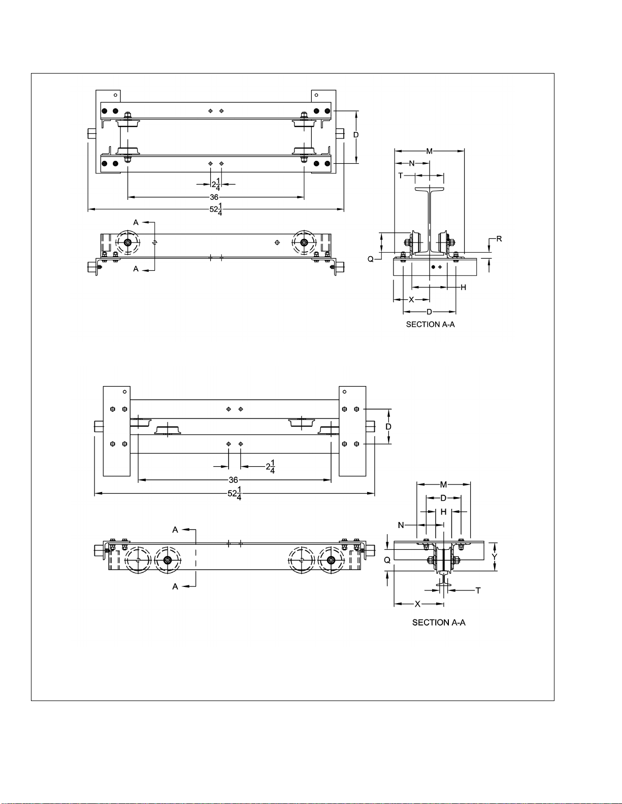
2.1.3 Dimensions
Refer to Table 2-1 and Figure 2-1 below.
Table 2-1 HPC500 End Truck Specifications & Dimensions (refer to Figure 2-1)
Code
Max.
Span
(ft)
T
Width of Flange or
Rail Head
(in)
D*
(in)
H*
End
Truck
Frame
Spacing
(in)
M*
End
Truck
Frame
Width
(in)
N†
Runway
Ctr. Line to
Outer Edge
of End
Truck
(in)
Q
Wheel
Tread
Diameter
(in)
X**
Width
Beyond
Span
(in)
Y
Wheel
Running
Surface to
Bridge
Beam
(in)
R
Wheel
Running
Surface to
Bridge
Beam
(in)
End Truck
Weight
(lbs/pair)
TR
UH
HPC505
24
1.5 –8.5
3 –8.5
T + 4¾
T + 1¼
T + 7.3
M/2
3.12
10⅛-
T/2
4.3
1.2
173
HPC510
T + 8.3
4.00
5.3
1.2
221
HPC520
3.3 –8.5
4.88
5.9
1.1
284
* Formulashown is for S beams &ASCE rail. Add ¼inch forW beams and rectangular bar.
** Formula shown is for flanges up to (and including) 6”. For flanges up to 8.5”, formula is 12 5/8 – T/2.
†Formula for N applies when flange is known at order entry. HPC kit includes un-cut end bracket ; for un-cut bracket use
Formula for X.
8
Underhung
Top Running
Figure 2-1 HPC500 End Truck Dimensions (refer toTable 2-1)

9
2.2 Part Names
END TRUCK
BRIDGE BEAM
BRIDGE BEAM
END TRUCK
BRACE
BRACE
TOP RUNNING
UNDERHUNG
RUNWAY RAIL
RUNWAY BEAM
Figure 2-2 Part Names –Crane System

10
UNDERHUNG
TOP RUNNING
BUMPER
WHEEL
FRAME
END
BRACKET B
SWEEP
END
BRACKET A
BUMPER
END
BRACKET B WHEEL
FRAME
SWEEP
END
BRACKET A
Figure 2-3 Part Names –End Truck

11
3.0 Pre - operational Procedures
3.1 Runway
3.1.1
Crane systems must be intalled on runways that are properlydesigned, fabricated,
installed, and supported. The runwaymust meet the requirements of CMAA Specification 74.
3.1.2
Read through all steps completely before proceeding with installation.
3.1.3
All operations associated with the assembly and installation of the end trucks
and/or the crane system should be performed under the supervision of a Qualified Person (see Section
5 for the definition of Qualified Person).
3.1.4 Underhung –When HPC500 end trucks are assembled in the Underhung configuration, theyare
designed to fit runwaybeams as follows. If your runway beam does not meet these dimensional
requirements, contact your supplier for help.
End Truck
Beam FlangeWidth
Beam Depth
HPC505
3 to 8.5 inches
5 inches
HPC510
3 to 8.5 inches
6 inches
HPC520
3.33 to 8.5 inches
8 inches
means “greater than or equal to”
3.1.5 Top Running –When HPC500 end trucks are assembled in the Top Running configuration, theyare
designed to fit rail or square bar with a width between 1½ and 6 inches. Most commonly HPC500 end
trucks set up for Top Running applications use anyof the following sizes of ASCE Rail:: 25#, 30#, 35#,
or 40#. Alternately, you can use any of the following sizes of square bar: 1½ inch, 1¾ inch, or 2 inch.
3.1.6 End Stops –The owner/installer mustmake sure that the runway beams are equipped with end stops
to prevent the end trucks (or crane) from rolling off the end of the runwaybeams.
3.2 Bridge Beam
3.2.1
Read through all steps completely before proceeding with installation.
3.2.2
All operations associated with the assemblyand installation of the end trucks
and/or the crane system should be performed under the supervision of a Qualified Person (see Section
5 for the definition of Qualified Person).
3.2.3 Size –For the use of either a MANUAL or ELECTRIC HOIST on your HPC500 crane, use Table 3-1 to
select the beam to use as the Bridge Beam.

12
Table 3-1 Bridge Beams for a MANUAL or ELECTRIC HOIST on an HPC500 Crane
Important information about this table:
Includes 15% Allowance for Electric Hoist Load Factor.
Based on Harrington’s manual chain hoist product.
For spans greater than 10ft., braces between endtruck & bridge beam should be used.
Cap.
(Tons)
Maximum Allowable Span (ft)
10
15
20
24
½
S8 X 18.4
S8 X 18.4
S8 X 18.4
S10 X 25.4
1
S8 X 18.4
S8 X 18.4
S10 X 25.4
S10 X 25.4
2
S10 X 25.4
S10 X 25.4
S12 X 31.8
S12 X 31.8
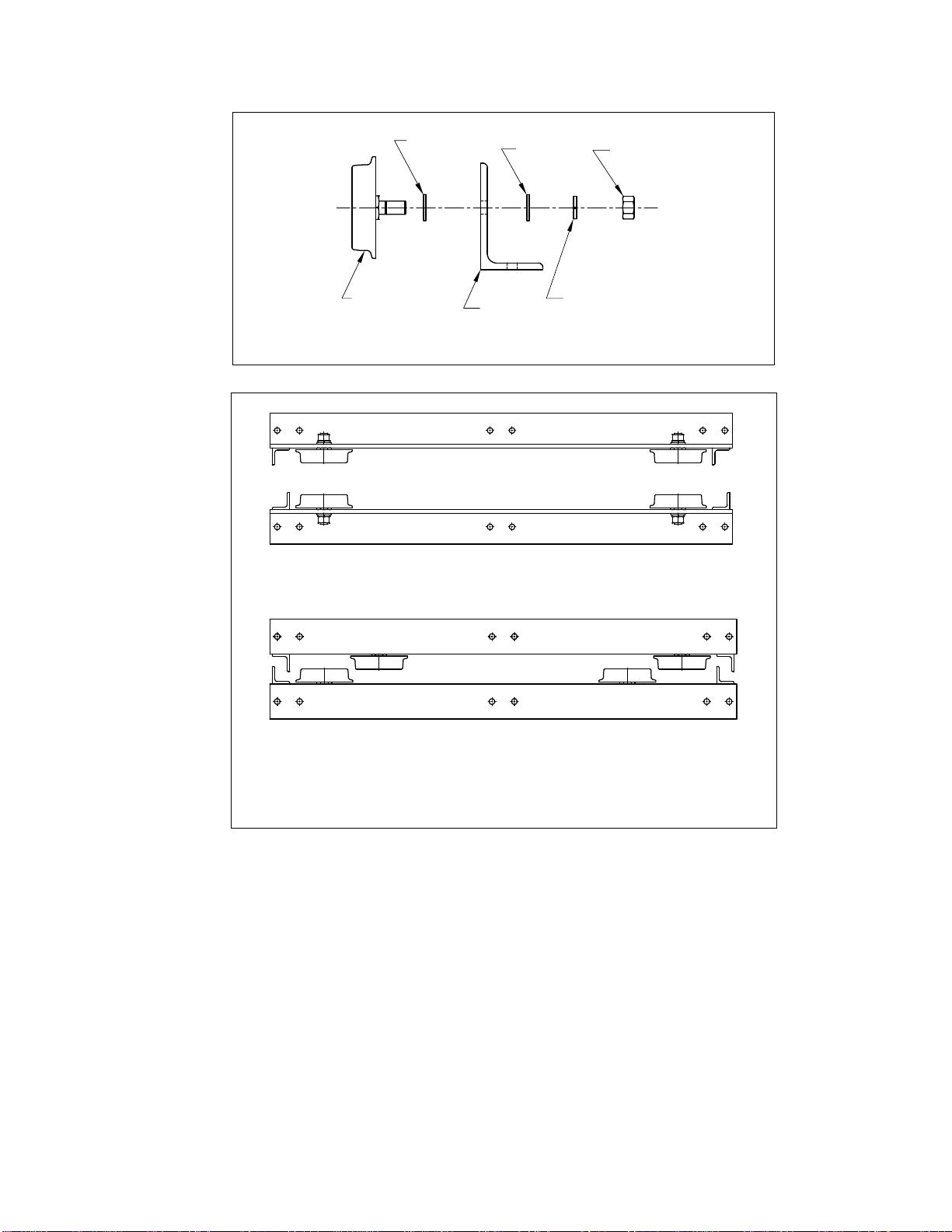
3.2.4 Fabrication –Preparation of the Bridge Beam for assembly with the HPC500 End Trucks requires that
holes be drilled in the beam as follows. Refer to Table 2-1 and Figure 2-1 for definitions of all letter
variables used for dimensions. NOTE –For S6 beams mounting plates must be welded to the beam.
Refer to the Bridge Beam AssemblyDrawing (Underhung: Drawing. No. 62673; Top Running:
Drawing. No. 62672) for details.
Underhung –Drill eight 9/16” diameter holes through the top flange as shown in Figure 3-1. Drill
four 9/16” diameter holes through the web as shown in Figure 3-2.
Top Running –Drill eight 9/16” diameter holes through the bottom flange as shown in Figure 3-1.
Drill four 9/16” diameter holes through the web as shown in Figure 3-3.
21
4
D
21
4
D
SPAN
D/2 D/2
Figure 3-1 Bridge Beam Flange Holes –UNDERHUNG &TOP RUNNING
10
2210
BEAM FLANGE HOLES
(from Fig. 3-1)
SPAN
Figure 3-2 Bridge Beam Web Holes - UNDERHUNG

13
7
22
BEAM FLANGE HOLES
(from Fig. 3-1)
SPAN 7
Figure 3-3 Bridge Beam Web Holes –TOP RUNNING
3.2.5 End Stop Installation –This step covers the installation of the end stops onto the bridge beam.
Locate the holes that were installed in the web of the bridge beam (step 3.2.4 above). These are
the holes for attaching the end stops to the bridge beam.
Attach the four (4) end stops to the bridge beam in accordance with Figure 3-4. Fully tighten the
fasteners byapplying 75 ft-lb of torque.
HEX-HEAD
CAP SCREW
END STOP
SPRING WASHER
HEX NUT
BRIDGE BEAM
BRIDGE BEAM
END STOP
Figure 3-4 End Stop Installation

14
3.3 End Trucks
3.3.1
Read through all steps completely before proceeding with installation.
3.3.2
All operations associated with the assemblyand installation of the end trucks
and/or the crane system should be performed under the supervision of a Qualified Person (see Section
5 for the definition of Qualified Person).
3.3.3 End Bracket Preparation –Prior to assembling the end trucks prepare the four (4) end brackets (2 end
brackets per end truck) as follows:
Measure “T” for the runway that the end trucks will be installed on. For Underhung “T” is the flange
width of the runway beam; for Top Running “T” is the width of the rail head or square bar
(whichever is being used).
Drill two 9/16” diameter holes in each of the four (4) end brackets in accordance with Figure 3-5.
4 REF.
13
4REF.
1 REF.
41
2REF.
17 REF.
D
EXISTINGØ9
16 HOLES BRACKET "A" (AS
SHOWN)
BRACKET "B" (OPPOSITE HAND)
Ø9
16 - 2 HOLES (DRILL THESE HOLES)
FORMULA
FOR "D"
D = T + 5
D = T + 43
4
D = T + 5
D = T + 43
4
BEAM WITH FLAT FLANGE
BEAM WITH TAPERED FLANGE
RECTANGULAR SHAPED RAIL
ASCE RAIL
UNDERHUNG
TOP
RUNNING
RUNNING
SURFACE
CRANE
CONFIG.
"D" DIMENSION (INCHES)
T = I-BEAM FLANGE OR RAIL HEAD
- WIDTH MEASUREMENT
Figure 3-5 End Bracket Holes
3.3.4 Wheel AssemblyInstallation –Install the Wheel Assemblies to the end trucks as shown in Figure 3-6.
Make sure you locate theWheel Assemblies properlyfor your application (Underhung or Top Running)
as shown in Figure 3-7. To prevent the axle from turning when tightening the hex nut, use an air-
powered nut driver. Then, finalize the installation by applying torque to each wheel’s hex nut as follows.
75 ft-lb for HPC505
150 ft-lb for HPC510 and HPC520
15
WHEEL
ASSEMBLY
FLAT WASHER
(HPC 505 ONLY)
FRAME*
FLAT WASHER
LOCK
WASHER
HEX NUT
*NOTE: DROP
STOP NOT
SHOWN FOR
CLARITY.
Figure 3-6 Wheel Assembly Installation
Underhung
Top Running
Figure 3-7 Wheel Mounting Locations
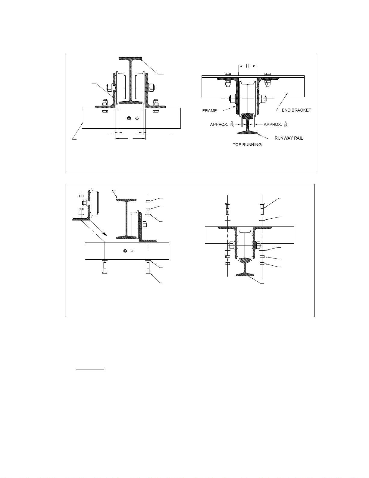
3.3.5 Verify “H” Dimension – The “H” dimension is the End Truck Frame Spacing (see Table 2-1 and Figure
2-1). By verifying the “H” dimension you verify that the end bracket holes are correct for proper fit of the
end truck onto the runway. Proceed as follows:
Calculate the “H” dimension for your application. For S Beams and ASCE Rail H = T + 1¼
(inches). ForW Beams and Square Bar H = T + 1½ (inches). Note: T is the measurement from
step 3.3.3 above.
Refer to Figure 2-3 and Figure 3-9 and assemble the frames and end brackets together. As you
tighten the fasteners (don’t fully tighten yet – this comes later) measure the actual “H” dimension in
accordance with Figure 3-8. Verify that the measured “H” dimension and the calculated “H”
dimension are the same.
Match mark the end brackets to the frames to ensure the “H” dimension is held for the following
steps.
16
END BRACKET
FRAME
RUNWAY BEAM
APPROX. 3
16 APPROX. 3
16
UNDERHUNG
H
Figure 3-8 Verify “H” Dimension
HEX-HEAD
CAP
SCREW
FLAT
WASHER
HEX NUT
FLAT
WASHER
HEX NUT
RUNWAY BEAM
UNDERHUNG
HEX NUT
FLAT
WASHER
HEX NUT
FLAT
WASHER
RUNWAY RAIL
HEX-HEAD CAP
SCREW
TOP RUNNING
Figure 3-9 End Truck Assembly& Installation
3.3.6 End Truck Assembly& Installation –Here the assembly of the end trucks is completed and theyare
installed onto the runway. Orientation of the end trucks on the runway is important. Make sure you put
each end truck onto the runway so that the hole in the end bracket for the brace is on the inside of the
runway(see Figure 2-2).
Underhung –apply the following steps for each end truck:
-Disassemble a frame from the end truck.
-Place the frame with the end brackets still attached to it onto the runwaybeam so its wheels
ride on the lower flange of the runwaybeam in accordance with the Underhung part of Figure
3-9.
-In the same manner place the other frame on the opposite side of the runway beam and
reassemble this frame to the end brackets, again in accordance with the Underhung part of
Figure 3-9.
17
-Ensure that the “H” dimension is correct as determined in step 3.3.5 above, and tighten the
fasteners byapplying 75 ft-lb of torque.
Top Running –applythe following steps for each end truck:
-Ensure that the “H” dimension is correct as determined in step 3.3.5 above, and tighten the
fasteners byapplying 75 ft-lb of torque.
-Place the end truck onto the runway rail (or square bar) in accordance with the Top Running
part of Figure 3-8.
-Since the end truck will not staybalanced on the runway in this condition, temporarily support it
so that it stays safelybalanced in position until the bridge beam is installed.
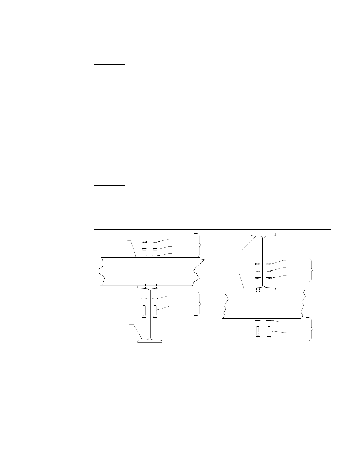
3.3.7 Bridge Beam Installation –This step covers the installation of the bridge beam onto the end trucks.
Underhung –As shown in Figure 2-2 for Underhung cranes, the bridge beam is attached to the
under side of the end trucks.
-Attach the bridge beam to the under side of the end trucks in accordance with the Underhung
part of Figure 3-10. Do not yet fully tighten the fasteners.
-Ensure the crane is square in accordance with Figure 3-11 and proceed to fully tighten the
fasteners byapplying 75 ft-lb of torque.
Top Running –As shown in Figure 2-2 for Top Running cranes, the bridge beam is attached to the
upper side of the end trucks.
-Attach the bridge beam to the upper side of the end trucks in accordance with the Top
Running part of Figure 3-10. Do not yet fully tighten the fasteners.
-Ensure the crane is square in accordance with Figure 3-11 and proceed to fully tighten the
fasteners byapplying 75 ft-lb of torque.
HEX-HEAD
CAP SCREW
TAPER
WASHER
HEX NUT
FLAT WASHER
HEX NUT
UNDERHUNG
BRIDGE
BEAM
END TRUCK
FRAME
4 PER
END
TRUCK
4 PER
END
TRUCK
HEX-HEAD
CAP SCREW
TAPER
WASHER
HEX NUT
FLAT
WASHER
HEX NUT
TOP RUNNING
4 PER
END
TRUCK
4 PER
END
TRUCK
END TRUCK
FRAME
BRIDGE
BEAM
Figure 3-10 Bridge Beam Installation –Attaching the Bridge Beam to the End Truck

18
90°
90°
END
TRUCK
BRIDGE
BEAM
Figure 3-11 Crane Squareness
3.4 Pre-operational Checks and Trial Operation
3.4.1 Record the end trucks’ Code and Serial No. from the nameplate (see Figure 10-1) in the space
provided on the cover of this manual.
3.4.2 Ensure that the end trucks are properlyinstalled on the runway beams/rails.
3.4.3 If the end trucks are used aspart of an overhead travelling bridge crane, then make sure that the bridge
beam is properlydesigned, fabricated, and installed.
3.4.4 If a hoist/trolley is used in the system:
Ensure the hoist/trolley is properly installed in accordance with the manufacturer’s requirements
and recommendations.
Ensure that the end stops on the bridge beam for the trolley motion are installed correctlyand
securely.
3.4.5 Prepare for Trial Operation
Before operating become familiar with operating the equipment (see Section 4 –Operation).
If a hoist/trolley is used in the system,perform pre-operational checks in accordance with the
manufacturer’s requirements and recommendations.
3.4.6 Trial Operation
If the end trucks are used as part of an overhead travelling bridge crane, then move the crane
along the entire lengthof the runway. Ensure that the crane has properclearance from
obstructions. Check for proper alignment and clearances of the crane and the end trucks to the
runway(refer to Figure 3-8 and Figure 3-11). Adjust as necessary. Make sure that after any
adjustments the fasteners are properly secured and tightened.
Perform inspections in accordance with Section 5.3, “Frequent Inspections”.
If a hoist/trolley is used in the system, perform trial operation in accordance with the manufacturer’s
requirements and recommendations.
3.4.7 Load Test –perform a load test in accordance with ASME B30.11, “Monorails and Underhung Cranes”,
or ASME B30.17, “Overhead and Gantry Cranes (Top Running Bridge, SingleGirder, Underhung
Hoist)”, whichever applies.

19
4.0 Operation
4.1 Introduction
Specific operation instructions are not provided herein because the HPC500 series end trucks are used in
systems not covered by this Owner’s Manual. Nevertheless, operation of systems using the HPC500 end trucks
is an EXTREMELY IMPORTANT issue –following is important information about operation.
4.2 Important Information About Operation
Do not walk under a suspended load.
Do not use HPC500 end trucks in systems that lift, support, or transport people.
Operators shall read materials pertaining to the operation of the equipment. For systems
using the HPC500 series end trucks, the supplier and/or owner of the system is/are responsible for providing
information for use by the operator for the safe operation of the system. Sources for such materials include:
Manufacturer –If a hoist/trolley(or some other type of equipment) is used in the system, then the
manufacturer should provide materials for the operation of the hoist/trolley(or other equipment).
CMAA –The Crane Manufacturer’s Association of America (CMAA) publishes a Crane Operator’s
Manual. Contact the CMAA at (704) 676-1190 or www.mhia.org/cmaa.
HMI –The Hoist Manufacturer’s Institute (HMI) publishes a Hoist Operator’s Manual. Contact the
HMI at (704) 676-1190 or www.mhia.org/hmi.
ASME –The American Societyof Mechanical Engineers publishes safetystandards pertaining to
the type of equipment that could be used in a system with the HPC500 end trucks. Examples are
listed below. Contact the ASME at (800) 843-2763 or www.asme.org.
-ASME B30.11, “Monorails and Underhung Cranes”
-ASME B30.16, “Overhead Hoists (Underhung)”
-ASME B30.17, “Overhead and Gantry Cranes (Top Running Bridge, Single Girder, Underhung
Hoist)”
Labels –Labels attached to equipment used in systems provide information important to the safe
operation of the equipment.
Operators should be trained to be aware of potential malfunctions of the equipment that
require adjustment or repair, and to be instructed to stop operation if such malfunctions occur, and to immediately
advise their supervisor so corrective action can be taken.
Operators should have normal depth perception, field of vision, reaction time, manual
dexterity, and coordination.
Operators should not have a history of, or be prone to siezures, loss of physical control,
physical defects, or emotional instability that could result in actions of the operator being a hazard to the operator
or others.
Operators should not operate equipment when under the influence of alcohol, drugs, or
medication.
Improper operation of systems using the HPC500 end trucks can create a potentially
hazardous situation which, if not avoided, could result in death or serious injury, and substatial property damage.
To avoid such a potentially hazardous situation the operator shall be familiar with, and shall obey, the operating
requirements and guidelines for the system.

20
5.0 Inspection
5.1 General
5.1.1 The inspection instructions herein are limited to the HPC500 Series End Trucks and Harrington-
designed HPC500 Cranes, and are based on the use of these products for overhead cranes and
monorails as defined bythe following standards.
ANSI/ASME B30.11 Monorails and Underhung Cranes
ANSI/ASME B30.16 Overhead Hoists (Underhung)
ANSI/ASME B30.17 Overhead and Gantry Cranes (Top Running Bridge, Single
Girder, Underhung Hoist)
For systems that are not addressed by these standards, the appropriate
inspection should be determined and overseen by a Qualified Person (see definition below).
5.1.2 The following definitions are from the standards listed in Section 5.1.1 above:
Designated Person - a person selected or assigned as being competent to perform the specific
duties to which he/she is assigned.
Qualified Person - a person who, bypossession of a recognized degree or certificate of
professional standing, or who, by extensive knowledge, training, and experience, has successfully
demonstrated the ability to solve or resolve problems relating to the subject matter and work.
Normal Service - service which involves operating at less than a certain percentage of rated load
and less than a specified frequency. Refer to the applicable ANSI/ASME B30 standards for the
specific definition for your application.
Heavy Service - that service which involves operation within the rated load limit which exceeds
normal service.
Severe Service - that service which involves normal or heavyservice with abnormal operating
conditions.
5.2 Inspection Classification
5.2.1 Initial Inspection –Prior to initialuse, a Designated Person shall inspect the equipment to verify
compliance with the applicable provisions of this manual.
5.2.2 Inspection Intervals –Inspections are divided into two general classifications based upon the intervals
at which inspection should be performed. The intervals in turn are dependent upon the nature of the
critical components and the degree of their exposure to wear, deterioration, or malfunction. The two
general classifications are designated as FREQUENT and PERIODIC, with respective intervals
between inspections as defined below.
5.2.3 FREQUENT Inspection –Visual examinations bytheoperator or other Designated Person with
intervals per the following criteria:
Normal service - monthly
Heavyservice - weeklyto monthly
Severe service - daily to weekly
Special or Infrequent Service –as recommended bya Qualified Person
5.2.4 PERIODIC Inspection –Visual inspection bya Designated Person with intervals per the following
criteria:
Normal service - yearly
Heavyservice - semiannually
This manual suits for next models
3
Table of contents
Other KITO Truck manuals


