Presto Lifts HPT 50 Series User manual

HPT
50 & 55 Series
Hydraulic Hand Pallet Trucks
Operating instructions
spare parts list
service manual
Model Number ___________________
Serial # _________________________
Date Placed in Service _____________
IMPORTANT: READ CAREFULLY
BEFORE INSTALLING OR OPERATING LIFT
Part orders are subject to a $50 minimum charge.
September 2015

Page 2 — PRESTO OWNER’S MANUAL: HPT 50 & 55 SERIES
This manual was current at the time of printing. To obtain the lat-
est, most updated version, please contact Presto Lifts Customer
Service Department or go to our website: www.PrestoLifts.com
-- you will nd a complete list of current owner’s manuals to print.

PRESTO OWNER’S MANUAL: HPT 50 & 55 SERIES — Page 3
C O N T E N T S
Handle Assembly Instruction ........................................................................................... 6
FIGURE 1: LIFT EXPLODED VIEW (after September 2008) .................................................... 7
TABLE 1: LIFT ITEMS (after September 2008) ....................................................................... 8
FIGURE 2: LIFT EXPLODED VIEW (prior to September 2008) ................................................ 9
TABLE 2: LIFT ITEMS (prior to September 2008)................................................................. 10
FIGURE 3: PUMP AND HANDLE EXPLODED VIEW (prior to September 2008)..................... 11
TABLE 3: PUMP AND HANDLE ITEMS (prior to September 2008) ........................................ 12
Instructions ...................................................................................................................... 13
Service Manual ................................................................................................................ 14
The Principle of Hydraulic Pump .................................................................................... 15
Troubleshooting ............................................................................................................... 16
1. Truck will not lift .........................................................................................16-17
2. Lift drops automatically.................................................................................... 18
3. Lift will not drop............................................................................................... 19
4. Truck is leaking................................................................................................. 19
5. Wheel Problem.................................................................................................. 20
6. Change or Add Oil .......................................................................................20-21
Three Month Maintenance Schedule ............................................................................... 22
ORDERING REPLACEMENT PARTS .......................................................................... 22
RESTOCKING POLICY ................................................................................................ 23
WARRANTY................................................................................................................... 24

Page 4 — PRESTO OWNER’S MANUAL: HPT 50 & 55 SERIES
Responsibility of Owners and Users
Inspection and Maintenance
The device shall be inspected and maintained in proper working order in accordance with Presto’s
owner’s manual.
Removal from Service
Any device not in safe operating condition such as, but not limited to, excessive leakage, missing
rollers, pins, or fasteners, any bent or cracked structural members, cut or frayed electric, hydraulic,
or pneumatic lines, damaged or malfunctioning controls or safety devices, etc. shall be removed from
service until it is repaired to the original manufacturer’s standards.
Repairs
All repairs shall be made by qualied personnel in conformance with Presto’s instructions.
Operators
Only trained personnel and authorized personnel shall be permitted to operate PowerStak.
Before Operation
Before using the device, the operator shall have:
• Read and/or had explained, and understood, the manufacturer’s operating instructions and safety
rules.
• Inspected the device for proper operation and condition. Any suspect item shall be carefully ex-
amined and a determination made by a qualied person as to whether it constitutes a hazard. All
items not in conformance with Presto’s specication shall be corrected before further use of the
PowerStak.
During Operation
The device shall only be used in accordance with this owner’s manual.
• Do not overload.
• Ensure that all safety devices are operational and in place.
Modications or Alterations
Modications or alterations to any Presto industrial positioning equipment shall be made only with
written permission from Presto.

PRESTO OWNER’S MANUAL: HPT 50 & 55 SERIES — Page 5
SAFETY ALERT SYMBOLS AND SIGNAL WORDS
The safety of all persons operating, maintaining, repairing, or in the vicinity of this equipment is of paramount
concern. This is a powerful machine with moving parts, and is capable of causing personal injury if proper precautions
are not taken. Therefore, throughout this manual, certain hazards have been identied which may occur in the use
of the machine, and there are appropriate instructions or precautions which should be taken to avoid these hazards.
In some cases, there are consequences which may occur if instructions or precautions are not followed. Below are
the symbols and signal words along with their denitions referenced from ANSI Z535.4 - Product Safety Signs
and Labels.
Safety Alert Symbols
These are the safety alert symbols.. They are used to alert you to potential physical injury haz-
ards. Obey all safety messages that follow this symbol to avoid possible injury or death.
For use with DANGER signal word
(Red Background)
For use with WARNING signal word
(Orange Background)
For use with CAUTION signal word
(Yellow Background)
Signal Words
The meaning of different signal words as dened by ANSI Standard Z535.4 indicates the relative
seriousness of the hazardous situation.
DANGER indicates a hazardous situation which, if not avoided,
will result in death or serious injury.
WARNING indicates a hazardous situation which, if not avoided,
could result in death or serious injury.
CAUTION, used with the safety alert symbol, indicates a haz-
ardous situation which, if not avoided, could result in minor or
moderate injury.
NOTICE is used to address practices not related to personal
injury.
(Red Background)
(Orange Background)
(Yellow Background)
(Blue Background)
SAFETY
INSTRUCTIONS
SAFETY INSTRUCTIONS (or equivalent) signs indicate safety-
related instructions or procedures.
(Green Background)

Page 6 — PRESTO OWNER’S MANUAL: HPT 50 & 55 SERIES
Handle Assembly Instruction
1. Make sure the symbol
on the handle and pump
are the same
2. Take out screw (1-21)
Hit out shaft (1012)
3. Put handle on pump body, then
take out the chain from handle. Hit in
shaft (1-12)
4. Insert chain through
shaft (1-12)
5. Connect chain with acti-
vator (1-38)
6. First, put spring pin (1-
21) in pump. Then, put in
screw (1-21)
7. Take out steel axle from
pump
8. Depress pump handle about 10 times
while keeping ngertip on "Lower Position" to
release air from pump
PRESTO OWNER’S MANUAL: HPT 50 & 55 SERIES — Page 7
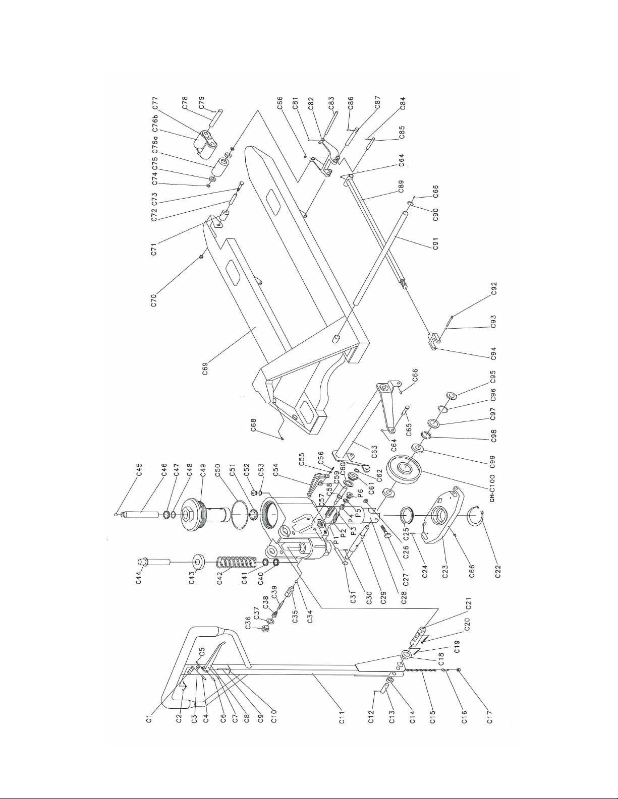
Figure 1. Lift Exploded View After September 2008

Page 8 — PRESTO OWNER’S MANUAL: HPT 50 & 55 SERIES
No. Description Qty
C1 Spring 1
C2 Spring 1
C3 Roller 1
C4 Elastic Pin 1
C5 Elastic Pin 1
C6 Elastic Pin 1
C7 Elastic Pin 1
C8 Handle 1
C9 Join Blade 1
C10 Pull Rod 1
C11 Hand Tube 1
C12 Elastic Pin 1
C13 Pressure Roller Shaft 1
C14 Pressure Roller 1
C15 Chain 1
C16 Adjusting Screw 1
C17 Nut 1
C18 Bushing 1
C19 Elastic Pin 1
C20 Split Pin 1
C21 Pressure Shaft 1
C22 Retaining Ring for Axle 1
C23 Supporting Base 1
C24 Elastic Pin 2
C25 Bearing 1
C26 Nut 1
C27 Bolt 1
C28 Base Frame 1
C29 Shaft 1
C30 Retaining Ring for Axle 1
C31 Pin Lever 1
C34 Steel Bead 1
C35 Seat of Damping Valve 1
C36 Plug 1
No. Description Qty
C37 Copper Washer 1
C38 Spring 1
C39 Spindle of Damping 1
C40 U-Ring 1
C41 Dust Ring 1
C42 Spring 1
C43 Hood 1
C44 Small Piston Rod 1
C45 Steel Ball 1
C46 Big Piston Rod 1
C47 Dust Ring 1
C48 O-Ring 1
C49 Cylinder Liner 1
C50 O-Ring 1
C51 U-Ring 1
C52 Plug 1
C53 Copper Wash 1
C54 Lever Plate 1
C55 Nut 1
C56 Regulate Screw 1
C57 Spring 1
C58 O-Ring 1
C59 Valve Tappet 1
C60 Copper Washer 1
C61 Cupreous Sheath 1
C62 O-Ring 1
C63 Rocker Arm 1
C64 Oiler 4
C65 Pin 2
C66 Oiler 9
C68 Inside Hex Screw 1
C69 Fork Frame 1
C70 Nut 2
C71 Pilot Wheel 2
No. Description Qty
C72 Sheath 2
C73 Bolt 2
C74 Washer 4(8*)
C75 Bearing 4(8*)
C76a Single Fork Wheel 2(0*)
C76b Double Fork Wheel 0(4*)
C77 Nog of Fork Wheel 0(4*)
C78 Shaft for Double Wheel 0(4*)
C79 Elastic Pin 0(8*)
C81 Elastic Pin 2
C82 Frame of Fork Wheel 2
C83 Shaft of Fork Wheel 2
C84 Elastic Pin 2
C85 Short Shaft 2
C86 Elastic Pin 2
C87 Shaft 2
C89 Straight Tappet 2
C90 Elastic Pin 1
C91 Long Shaft 1
C92 Pin 2
C93 Retaining Ring for Axle 2
C94 Joint 2
C95 Dust Cover 2
C96 Retaining Ring for Axle 2
C97 Bowl Nut 2
C98 Half Circle 2
C99 Bearing 4
CH-
C100
Steel Wheel 2
P1 Steel Ball 1
P2 Steel Ball Base 1
P3 Spring 1
P4 Screw 1
P5 Copper Washer 1
P6 Plug 1
Table 1. Lift Items
After September 2008

PRESTO OWNER’S MANUAL: HPT 50 & 55 SERIES — Page 9
Figure 2. Lift Exploded View
Prior to September 2008

Page 10 — PRESTO OWNER’S MANUAL: HPT 50 & 55 SERIES
No. Descripon Qty
1.1 Handle assy 1
1.2 Pump assy. 1
2 Spring pin 2
3 Bearing 1
4 Spring pin 2
5 Pressure plate 1
6 Circlip 1
7 Wheelsha 1
9 Washer 2
10 Steering wheel assy. 2
10.1 Nylon wheel 2
10.2 PU cover cast iron 2
10.3 Rubber cover aluminum 2
10.4 PU cover aluminum 2
11 Circlip 2
12 Arm pin 2
13 Learm 1
14 Copper bush 2
14.1 Copper bush 2
14.2 Copper bush 2
14.3 Copper bush 4
14.4 Copper bush 2
15 Spring pin 2
16 Push pod 2
17 Spring pin 4
18 Exit roller 4
19 Spring pin 2
No. Descripon Qty
20 Sha 2
21 Load wheel frame 2
22 Spring pin 2
25 Sha 2
26 Sha 2
28 Single load wheel assy.
37-8E Bearing 6
27 Washer 2
37-5 Dust ring 6
37-7 Circlip 6
37 Load sheel 2
27-1 Washer 4
27-A Bush 4
37-3B Wheel plate 2
37-2B Nut 2
37-2A Sha 2
29 Tandem load wheel assy.
30 Circlip 2
31 Longsha 1
32 Fork body 1
33 Circlip 4
34 Entry roller 2
35 Sha 2
36 Cap of bearing 1
Table 2. Lift Items
PRESTO OWNER’S MANUAL: HPT 50 & 55 SERIES — Page 11
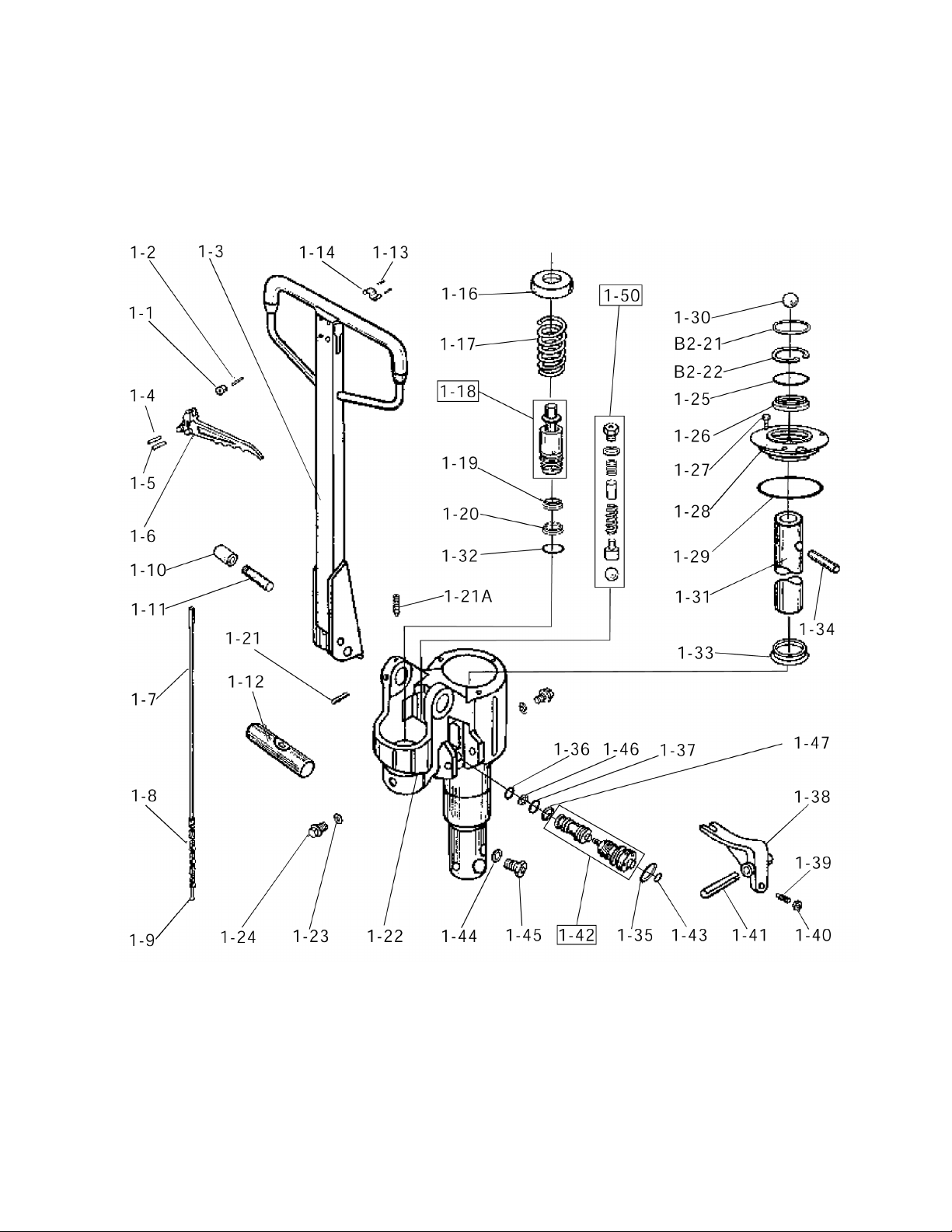
Figure 3. Pump and Handle Exploded View
*
*
*
*
*
*
**
*
*
*
Prior to September 2008

Page 12 — PRESTO OWNER’S MANUAL: HPT 50 & 55 SERIES
No. Descripon Qty
1-1 Stop rubber 1
1-2 Spring pin 1
1-3 Handle 1
1-4 Spring pin 1
1-5 Spring pin 1
1-6 Loweringlevel(ingerp) 1
1-7 Linkage 1
1-8 Chain 1
1-9 Chain rod 1
1-10 Pressure roller 1
1-11 Sha 1
1-12 Sha 1
1-13 Spring pin 1
1-14 Spring plate 1
1-16 Spring cap 1
1-17 Spring 1
1-18 Plunger assy. 1
1-19 Seal DH18 1
1-20 Seal DH18 1
1-21 Screw 1
1-21A Spring pin 1
1-22 Pump body 1
1-23 Washer 2
1-24 Screw plug 2
1-25 O-ring 1
No. Descripon Qty
1-26 Seal UN32 1
1-27 Screw 1
1-28 Pump cap 1
1-29 O-ring P62 1
1-30 Ball 1
B2-21 Washer 1
B2-22 Circlip 1
1-31 Cylinder 1
1-32 O-ring P31 1
1-33 Seal UN32 1
1-34 Pin 1
1-35 O-ring 1
1-36 O-ring 1
1-37 O-ring 1
1-38 Acvator 1
1-39 Bolt 1
1-40 Nut 1
1-41 Spring pin 1
1-42 Valve assy. 1
1-43 O-ring 1
1-44 Washer 1
1-45 Bolt 1
1-46 PU washer 1
1-47 PU washer 1
1-50 Overload valve assy 1
Table 3. Pump and Handle Items
Prior to September 2008
PRESTO OWNER’S MANUAL: HPT 50 & 55 SERIES — Page 13
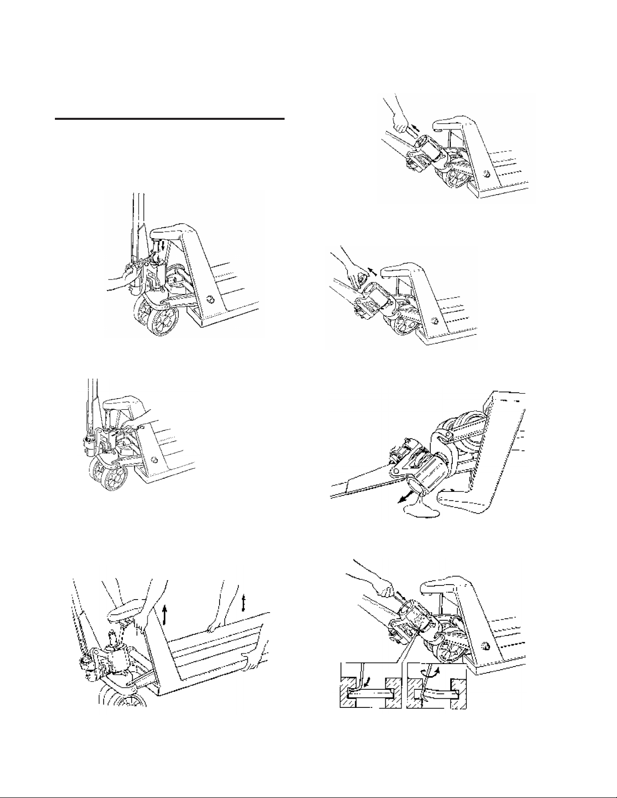
Instruction
Raised Position
Depress the lever and pump handle until pallet has
reached the desired height. A clearance of 1" be-
tween the oor and pallet is usually sufcient to move
the load. Do not lift load with one fork or extremity of
forks.
Neutral Position
The neutral position is found between the raise and
lower position. This neutral (drive) position disengag-
es the lifting mechanism making the handle free from
hydraulic resistance and becomes almost weightless,
yet the forks retain their raised position. Always use
the neutral position when moving a load.
Lowered Position
Pull the lever up to lower the forks. The lever is
spring loaded for lowering only, therefore when you
release the lever it will automatically return to the neu-
tral position.
WARNING
For safe operation of Hand Pallet Truck,
please read the following instructions:
1. Do not operate the Hand Pallet Truck unless
you are familiar with it and have been trained and au-
thorized to do so. Read all warnings and instructions
in this manual and on the machine.
2. Do not operate the Hand Pallet Truck until
you have checked its condition. Give special atten-
tion to the wheels, handle, forks, lift, and lower con-
trol. Do not operate damaged or faulty trucks. Do not
attempt repairs unless you are trained and authorized
to do so.
3. Operate Hand Pallet Trucks only from the
designated operating position. Never place any part
of your body in the lifting mechanism or under the
forks or load. Do not carry passengers.
4. Do not handle unstable or loosely stacked
loads. Use special care when handling long, high, or
wide loads to avoid losing the load, striking by-stand-
ers, or tipping the trucks.
5. Do not overload the truck. Check capacity
plate for carrying capacity information. Overloading
may cause truck to perform incorrectly.
6. The capacity of the Hand Pallet Truck as-
sumes an evenly distributed load with the center of
the load being at the halfway point of the length of the
forks.
7. Make sure the length of the forks match the
length of the pallet. Using a pallet truck where the
forks are longer than the pallet will damage the truck
if the pallet truck is pushed through the pallet and the
forks are under a second pallet behind the one being
lifted. When lowering the load, make sure the area
beneath the pallet is clear.
8. Observe trafc regulations. Yield right of way
to pedestrians. Stop at cross aisles.
9. Hand Pallet Trucks are for general operation on
level, at hard surfaces.
10. It is recommended that the operator wear se-
curity shoes when using the Hand Pallet Truck.
Failure to follow these
instructions may cause
serious injury to the
operator or others
Page 14 — PRESTO OWNER’S MANUAL: HPT 50 & 55 SERIES
HPT 50 & 55 Series
Service Manual

PRESTO OWNER’S MANUAL: HPT 50 & 55 SERIES — Page 15
The principle of hydraulic pump
(See gure 1-1)
Lifting
1. Put nger tip (1-6) on Lifting Position; Lift handle,
hydraulic oil ow from oil tank through channel A; Ball
A open; Oil ow to piston through channel B.
2. Press handle; Ball A closed, Ball B open; Oil ow
to sylinder from piston through channel B and channel
C; Cylinder lifted; Truck lifted.
Lower
1. Put nger tip (1-6) to Lowered Position
2. Part 1-39 move at D1 direction; Ball A and ball B
open; Oil ow to oil tank from cylinder through chan-
nel C, ball B, and channel A.
Transport
1. Put nger tip (1-6) to Neutral Position; Part 1-39
move at D1 direction; Ball A open.
2. Lift handle; Oil ow to piston from oil tank through
channel A.
3. Press handle; Oil ow to oil tank from piston
through channel B, ball A and channel A.
Figure 1-1. Cut-away pump diagram

Page 16 — PRESTO OWNER’S MANUAL: HPT 50 & 55 SERIES
Troubleshooting
1. Truck will not lift
1.3: Check symbol
Symbol on handle (1-3) and pump (1-5) must be the
same.
1.1: Release the air in pump
Put the nger tip to lower position. Pump handle
about 10 times.
1.2: Check the chain (1-8)
Check chain (1-8), if it doesn ot cross the shaft 1-12,
please ret it.
1.4a-c: Adjust the valve
1.4a: Release screw (1-40)
1.4c: Check if it can be lifted
If it still does not lift, move to step 1.5.
If the truck lifts:
1. Lift the truck to the top postiion
2. Put the ngertip to 1.4c position; screw nut (1-39)
conuterclockwise until the Hand Pallet Truck starts to
lower.
3. Screw 1-40
1.4b: Screw nut
(1-39) in a circle circle along counterclockwise direction

PRESTO OWNER’S MANUAL: HPT 50 & 55 SERIES — Page 17
1.5a-e: Replace Valve Assembly (1-42)
1.5a: Place the truck on its side
1.5b: Hit out spring pin (1-14) and take off
lowering level (1-38)
1.5d: Screw out copper brush of valve
assembly (1-42)
1.5c: Take the cylinder to the top position
1.5e: Take out valve corn of valve assem-
bly (1-42)
1. Install new valve assembly (1-42) including copper
brush, valve.
2. Fit spring pin (1-38)
3. Repeat step 1.4
Page 18 — PRESTO OWNER’S MANUAL: HPT 50 & 55 SERIES
2. Lift drops automatically
2.1a-h: Renew Seal (1-33)
2.1a: Take out circlip B2-22
2.1b: Screw off 1-27
2.1c: Take pump off from truck body
2.1d: Take out piston cylinder (1-31)
2.1e: Take cap off pump
2.1f: Pour out oil
2.1g: Renew Seal (1-33)
2.1h: Pour in new oil

PRESTO OWNER’S MANUAL: HPT 50 & 55 SERIES — Page 19
3. Lift will not drop
3.1 Check the chain (1-8)
1. Replace a broken chain
2. Check the shaft (1-12) and screw (1-21). Be sure
the shaft (1-12) is xed on pump body by screw (1-21).
If shaft (1-12) is not xed, the chain will be damaged by
handle operation. If the chain and shaft have no prob-
lem, continue to step 3.2.
3.2: Replace valve assembly (1-42)
Refer to step 1.5
4. Pallet Truck is leaking
4.1a-b: Leak from piston
4.1a: Take out 1-17
4.1b: Renew seal 1-19 & 1-20
4.2a-c: Leak from piston carriage
4.2a: Take out 1-17
4.2b: Take out 1-18
4.2c: Renew seal 1-32
Page 20 — PRESTO OWNER’S MANUAL: HPT 50 & 55 SERIES
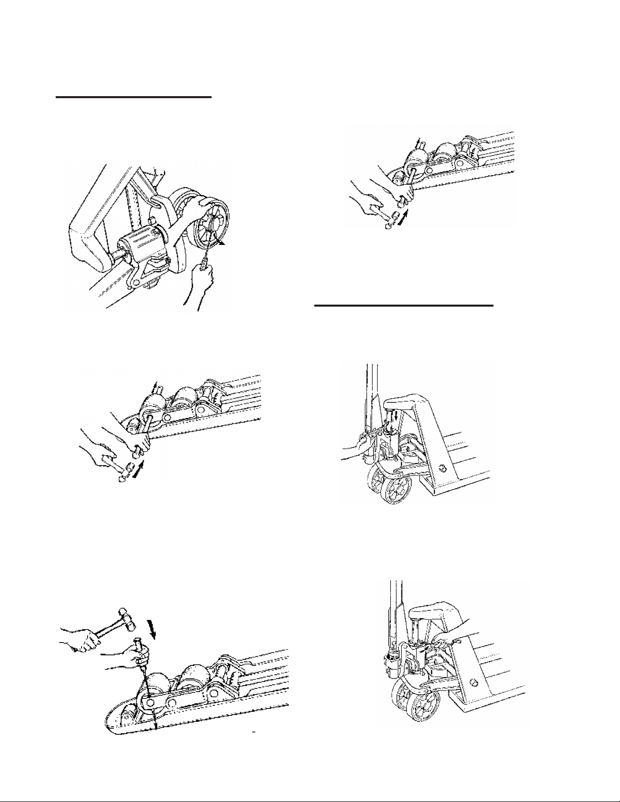
5. Wheel problem
5.1a-c: Problem of steering wheel
5.1a: Take off the wheel cap
5.1b: Take out circlip 11
5.1c: Change steering wheel
5.2a-c: Change load wheel
5.2a: Take out spring pin 22 & 23 & 24
5.2b: Hit out shaft
5.2c: Change load wheel
6. Change or add oil
6.1a-g: Change oil
6.1a: Take out circlip B22-2
6.1b Screw off 1-27
This manual suits for next models
1
Table of contents


