KITO HARRINGTON 3 Series User manual

END
TRUCKS
Top
Running &
Underhung
SERIES 3
1 Ton through 10 Ton Capacity
Model and Serial Number
EFFECTIVE: August 18, 2021
This equipment should not be installed, operated, or maintained by
any person who has not read and understood all the contents of this
manual. Failure to read and comply with the contents of this manual
can result in serious bodily injury or death, and/or property damage.

2
INSTALLATION, OPERATION, MAINTENANCE
AND PARTS MANUAL FOR SERIES 3 END
TRUCKS
Series 3 Top Running and Underhung End Trucks
Thank you for selecting Harrington’s Series 3 End Trucks for your material handling needs. We believe
the Series 3 End Truck will provide you years of trouble-free service when properly maintained. Further,
by applying the information in this manual, you will obtain dependable performance from our products.
The Harrington Series 3 End Truck was designed to operate either manually or with an electrical power
source. Therefore, it is important that you follow this manual to properly install and operate your Series 3
End Trucks. It is the owner’s and user’s responsibility to determine the suitability of a product for a
particular use. It is recommended that all applicable industry standards, federal, state, and local
regulations be checked concerning the installation, operation and maintenance of the Series 3 End
Trucks. Read all operating instructions and warnings before operation.

3
Table of Contents
Section Page Number
1.0 Important Information and Warnings………………………………………………………………………….5
1.1 Terms and Summary
1.2 Warning Tags and Labels
2.0 Technical Information…………………………………………………………………………………………..8
2.1 Specifications for Underhung End Trucks
2.2 Specifications for Top Running End Trucks
2.3 Component Names
2.4 Bridge Crane Design Requirements
3.0 Assembly, Installation and Test Trial Operation…………………………………………………………….24
3.1 Underhung End Trucks
3.2 Top Running End Trucks
3.3 Max-E-Lift End Trucks
3.4 Drive Shafts for Geared End Trucks
3.5 Crane Wiring
3.6 Power Source
3.7 Testing
4.0 Operation………………………………………………………………………………………………………36
5.0 Inspection……………………………………………………………………………………………………...37
5.1 General
5.2 Inspection Classification
5.3 Frequent Inspection
5.4 Periodic Inspection
5.5 Occasionally Used End Trucks
5.6 Inspection Records
5.7 Inspection Methods and Criteria

4
Section Page Number
6.0 Lubrication…………………………………………………………………………………………………….. 44
7.0 Maintenance & Handling……………………………………………………………………………………...45
7.1 General
7.2 Gear Motor -Reduction Gear
7.3 Gear Motor - Brake
7.4 Brake Adjustment
7.5 Storage
7.6 Outdoor Installations
8.0 Troubleshooting……………………………………………………………………………………………….49
9.0 Warranty……………………………………………………………………………………………………….52
10.0 Parts List……………………………………………………………………………………………………….53

5
1.0 Important Information and Warnings
1.1 Terms and Summary
This manual provides important information for personnel involved with the installation, operation and
maintenance of this product. Although you may be familiar with this or similar equipment, it is strongly
recommended that you read this manual before installing, operating, or maintaining the product.
Danger, Warning, Caution, and Notice
Throughout this manual, there are steps and procedures that can present hazardous situations. The following
signal words are used to identify the degree or level of hazard seriousness.
Danger indicates an imminently hazardous situation which, if not avoided, will result in
death or serious injury, and property damage.
Warning indicates an imminently hazardous situation which, if not avoided, could result in
death or serious injury, and property damage.
Caution indicates a potentially hazardous situation which, if not avoided, may result minor
or moderate injury or property damage.
Notice is used to notify people of installation, operation, or maintenance information which
is important but not directly hazard-related.
These general instructions deal with the normal installation, operation, and maintenance situations
encountered with the equipment described herein. The instructions should not be interpreted to
anticipate every possible contingency or to anticipate the final system, crane, or configuration that uses
this equipment. For systems using the equipment covered by this manual, the supplier and owner of the
system are responsible for the system's compliance with all applicable industry standards, and with all
applicable Federal, State, and Local regulations/codes.
This manual includes instructions and parts information for a variety of end truck types. Therefore, all
instructions and parts information may not apply to any one type or size of specific end truck. Disregard
those portions of the instructions that do not apply.
Record your end truck’s Model Type and Serial Number on the front cover of this manual for
identification and future reference to avoid referring to the wrong manual for information or instructions
on installation, operation, inspection, maintenance, or parts.
Use only Harrington authorized replacement parts in the service and maintenance of your Harrington
end trucks.

6
Equipment described herein is not designed for and MUST NOT be used for lifting, supporting, or
transporting people, or for lifting or supporting loads over people.
Equipment described herein should not be used in conjunction with other equipment unless necessary
and/or required safety devices applicable to the system, crane, or application are installed by the system
designer, system manufacturer, crane manufacturer, installer, or user.
Modifications to upgrade, rerate, or otherwise alter this equipment shall be authorized only by the original
equipment manufacturer.
Equipment described herein may be used in the design and manufacture of cranes or monorails. Additional
equipment or devices may be required for the crane and monorail to comply with applicable crane design
and safety standards. The crane designer, crane manufacturer, or user is responsible to furnish these
additional items for compliance. Refer to ANSI/ASME B30.16, Safety Standard for Overhead Hoists;
ANSI/ASME B30.2 Safety Standard for Top-Running Double-Girder Cranes; and ANSI/ASME B30.11 Safety
Standard for Underhung Cranes and Monorails.
If a below-the-hook lifting device or sling is used with a hoist, refer to ANSI/ASME B30.9, Safety Standard
for Slings, or ANSI/ASME B30.20, Safety Standard for Below-the-Hook Lifting Devices.
Hoists and cranes, used to handle hot molten material may require additional equipment or devices. Refer
to ANSI Z241.2, Safety Requirements for Melting and Pouring of Metals in the Metalcasting Industry.
Failure to read and comply with any one of the limitations noted herein can result in serious bodily injury or
death, and/or property damage.
HAZARDOUS ELECTRICAL POWER IS PRESENT IN THE END TRUCK MOTOR, IN THE SUPPLY OF
ELECTRICAL POWER TO THE END TRUCK MOTOR, AND IN THE CONNECTIONS BETWEEN
COMPONENTS.
Before performing ANY maintenance on the equipment, de-energize the electrical supply to the equipment,
and lock and tag the supply device in the de-energized position. Refer to ANSI Z244.1, “Personnel
Protection - Lockout/Tagout of Energy Sources.”
Only trained and competent personnel should inspect and repair this equipment.

7
It is the responsibility of the owner/user to install, inspect, test, maintain, and operate the equipment
covered by this manual in accordance with the applicable ANSI/ASME B30 volume(s) and OSHA
Regulations.
It is the responsibility of the owner/user to have all personnel that will install, inspect, test, maintain, and
operate the equipment covered by this manual read the contents of this manual and applicable portions of
ANSI/ASME B30 volume(s), and OSHA Regulations.
If the owner/user of the equipment covered by this manual requires additional information, or if any
information in the manual is not clear, contact Harrington or the distributor of the end truck. Do not install,
inspect, test, maintain, or operate this equipment unless this information is fully understood.
A regular schedule of inspection of the equipment in accordance with the requirements of ANSI/ASME
B30 volume(s) should be established and records maintained.
Responsibility for cranes using Harrington Series 3 End Trucks:
•For cranes where HARRINGTON fabricates the bridge, Harrington is responsible for
the design of the crane based on information supplied by the customer at the time of
order.
•For cranes where OTHERS fabricate the bridge, the customer or fabricator is
responsible for the design of the crane.
1.2 Warning Tags and Labels
The End Trucks covered by this owner's manual may be used as part of a lifting system such as a crane. It is the
responsibility of the supplier and the owner of such a lifting system to provide for and ensure that the lifting
system be equipped with warning labels in accordance with applicable industry standards.
1.3 Conformance Statement
In order to meet requirements of the Crane Manufacturers Association of America (CMAA), the National
Electric Code (NEC) and the American National Standards Institute (ANSI/ASME) Harrington components
include:
•Thermal motor protection for all motors.
•Rubber bumpers
•Rubber bumpers and drop stops for motorized trolley hoists.
•Hoists load tested to 125% of rated capacity.
•Drop stops for all end trucks
•Rail sweeps for all end trucks
•Recommended bridge beams comply with CMAA.
8
2.0 Technical Information
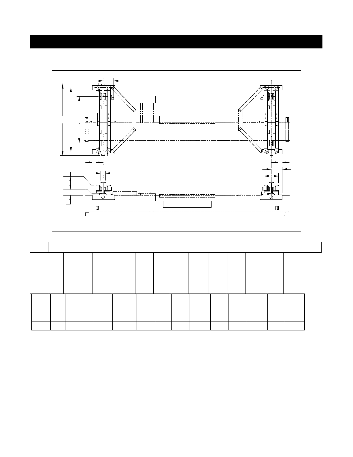
2.1 Specifications for Underhung End Trucks
Harrington Hoists, Inc.
ABD
E
E
T
U
YMX
AA
Figure 2-1 Underhung End Truck Dimensions
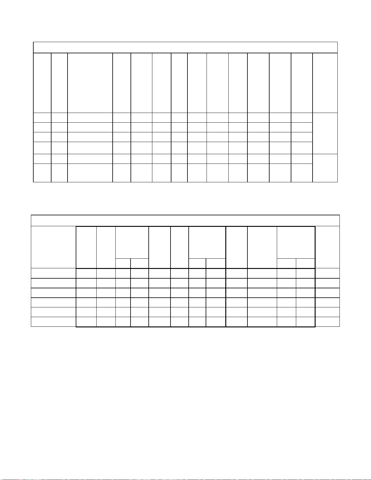
Underhung Push (Manual) End Trucks (Refer to Fig. 2-1)
Max.
Cap.
(Tons)
Max.
Span
(ft)
End Truck
Model # Wheel
Dia.
(in)
Flange
Range
Std. (in)
A
Overall
Length
(in)
B
Roller
Base
(in)
D
Wheel
Base
(in)
E *
Beam
Beyond
Span
(in)
M
End
Truck
Frame
Width
(in)
U
**
Wheel
Bottom
to
Beam
Top
(in)
X
Width
Beyond
Span
(in)
Y
Height
(in)
End
Truck
Weight
(lbs/pr)
2 35 UP-3-0235 4.33 3 - 6 60 53 39 12 T+8.1 1.8 11.3-T/2
6.5 448
2 45 UP-3-0245 4.33 3 - 6 82 75 61 12 T+8.1 1.8 11.3-T/2
6.5 585
3 35 UP-3-0335 4.92 3 - 6 60 53 35 12 T+8.2 1.9 11.3-T/2
6.5 472
5 35 UP-3-0535 5.51 4 - 6 60 53 33 12 T+9.8 2.0 11.3-T/2
6.4 546
* minimum overhang is M/2
** includes 3/8" thick beam mounting plates

9
Underhung Geared End Trucks (Refer to Fig. 2-1)
Max.
Cap.
(Tons)
Max.
Span
(ft)
End Truck
Model # Wheel
Dia.
(in)
Flange
Range
Std. (in)
A
Overall
Length
(in)
B
Roller
Base
(in)
D
Wheel
Base
(in)
E *
Beam
Beyond
Span
(in)
J
Hand
Wheel
Offset
(in)
M
End
Truck
Frame
Width
(in)
U
**
Wheel
Bottom
to
Beam
Top
(in)
X Width
Beyond
Span (in)
Y
Wheel
Running
Surface
to
Upper
Most
Part of
ET
(in)
End
Truck
Weigh
t
(lbs/pr
)
2 35 UG-3-0235 4.33 3 - 6 60 53 39 12 T/2+9.0 T+8.1 1.8 11.3-T/2 6.5 503
2 45 UG-3-0245 4.33 3 - 6 82 75 61 12 T/2+9.0 T+8.1 1.8 11.3-T/2 6.5 640
3 35 UG-3-0335 4.92 3 - 6 60 53 35 12 T/2+8.9 T+8.2 1.9 11.3-T/2 6.7 529
3 45 UG-3-0345 4.92 3 - 6 82 75 57 12 T/2+8.9 T+8.2 1.9 11.3-T/2 6.7 666
5 35 UG-3-0535 5.51 4 - 6 60 53 33 12 T/2+9.0 T+9.8 2.0 11.3-T/2 6.8 611
5 45 UG-3-0545 5.51 4 - 6 82 75 55 12 T/2+9.0 T+9.8 2.0 11.3-T/2 6.8 768
* minimum overhang is M/2
** includes 3/8" thick beam mounting plates
10
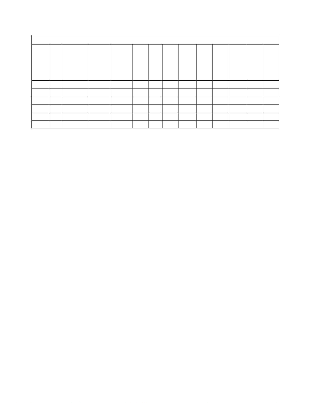
Underhung Motorized End Trucks (Refer to Fig. 2-1)
Max.
Cap.
(Tons)
Max.
Span
(ft)
En
d Truck
Model # Wheel
Dia.
(in)
Flange
Range
Std.
(in)
A
Overall
Length
(in)
B
Roller
Base
(in)
D
Wheel
Base
(in)
E *
Beam
Beyond
Span
(in)
M
End
Truck
Frame
Width
(in)
U **
Wheel
Bottom
to Beam
Top
(in)
X
Width
Beyond
Span
(in)
Y
Wheel
Running
Surface
to
Upper
Most
Part of
ET
(in)
AA
Span to
Motor
End (in)
2 35 UML/S/H/D-3-0235
4.33 3 - 6 60 53 39 12 T+8.1 1.8 11.3-T/2 6.5 T/2+11.9
(L/S)
T/2+12.3
(H)
T/2+13.3
(D)
2 50 UML/S/H/D-3-0250
4.33 3 – 6 82 75 61 12 T+8.1 1.8 11.3-T/2 6.5
3 35 UML/S/H/D-3-0335
4.92 3 – 6 60 53 35 12 T+8.2 1.9 11.3-T/2 6.5
3 50 UML/S/H/D-3-0350
4.92 3 – 6 82 75 57 12 T+8.2 1.9 11.3-T/2 6.5
5 35 UML/S/H/D-3-0535
5.51 4 - 6 60 53 33 12 T+9.8 2.0 11.3-T/2 6.8 T/2+13.7
(L/S/D)
T/2+14.2
(H)
5 50 UML/S/H/D-3-0550
5.51 4 - 6 82 75 55 12 T+9.8 2.0 11.3-T/2 6.8
* minimum overhang is M/2
** includes 3/8" thick beam mounting plates
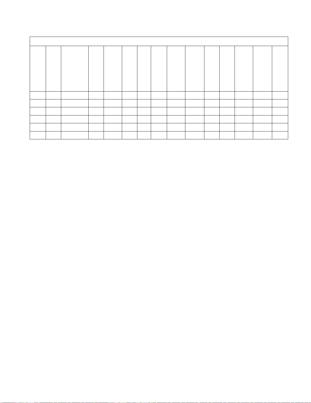
Underhung Motorized End Truck - Gear Motors
End Truck
Model # Travel
Speed
(FPM)
Motor
Power
(Hp)
Ea. of
Two
Current
(AMPS) Ea.
of Two
Travel
Speed
(FPM)
Motor
Power
(Hp)
Ea. of
Two
Current
(AMPS) Ea. of
Two
Travel
Speed
(FPM)
Motor
Power (Hp)
Ea. of Two
Current (AMPS)
Ea. of Two Motor
End
Truck
Weight
(lbs./pr)
230V 460V 230V 460V 230V 460V
UML/S/H/D-3-0235 40/80 0.33 1.6 1.0 120 0.5 2.1 1.3 80/20 0.33/0.08 1.6/1.1 0.9/0.8 522
UML/S/H/D-3-0250 40/80 0.33 1.6 1.0 120 0.5 2.1 1.3 80/20 0.33/0.08 1.6/1.1 0.9/0.8 659
UML/S/H/D-3-0335 40/80 0.33 1.6 1.0 120 0.5 2.1 1.3 80/20 0.33/0.08 1.6/1.1 0.9/0.8 543
UML/S/H/D-3-0350 40/80 0.33 1.6 1.0 120 0.5 2.1 1.3 80/20 0.33/0.08 1.6/1.1 0.9/0.8 680
UML/S/H/D-3-0535 40/80 0.50 2.1 1.3 120 1.0 3.3 2.0 80/20 0.50/0.13 2.0/1.5 1.2/0.9 638
UML/S/H/D-3-0550 40/80 0.50 2.1 1.3 120 1.0 3.3 2.0 80/20 0.50/0.13 2.0/1.5 1.2/0.9 795
Speed Code
L - Designates the speed of 40 feet per minute
S - Designates the speed of 80 feet per minute
H - Designates the speed of 120 feet per minute
D - Designates the speed of dual speed 80/20 feet per minute
Product code derivation - example: UML/S/H/D-3-0235
U - Underhung
M - Motorized
L/S/H/D - Speed code - available in 40, 80, 120, or dual 80/20 feet per minute - choose desired speed
3 – Series number
02 – Capacity - 2 ton
35 – Maximum span - 35 feet
11
Max-E-Lift Underhung Geared End Trucks (Refer to Fig. 2-1)
Max.
Cap.
(Tons)
Max.
Span
(ft)
End Truck
Model # Wheel
Diame
ter (in)
Flange
Range
Std. (in)
A
Overal
l
Length
(in)
B
Roller
Base
(in)
D
Wheel
Base
(in)
E *
Beam
Beyond
Span
(in)
J
Hand
Wheel
Offset
(in)
M
End
Truck
Frame
Width
(in)
U **
Wheel
Botto
m to
Beam
Top
(in)
X
Width
Beyond
Span
(in)
Y
Wheel
Running
Surface
to Upper
Most
Part of
ET
(in)
End
Truck
Weight
(lbs/pr)
2 35 MUG-3-0235 4.33 3 - 6 87 80 66 12 T/2+9.0 T+8.1 1.8 11.3-T/2 6.5 671
2 45 MUG-3-0245 4.33 3 – 6 99 92 78 12 T/2+9.0 T+8.1 1.8 11.3-T/2 6.5 746
3 35 MUG-3-0335 4.92 3 – 6 91 84 66 12 T/2+8.9 T+8.2 1.9 11.3-T/2 6.7 722
3 45 MUG-3-0345 4.92 3 – 6 103 96 78 12 T/2+8.9 T+8.2 1.9 11.3-T/2 6.7 797
5 35 MUG-3-0535 5.51 4 - 6 95 88 68 12 T/2+9.0 T+9.8 2.0 11.3-T/2 6.8 861
5 45 MUG-3-0545 5.51 4 - 6 107 100 80 12 T/2+9.0 T+9.8 2.0 11.3-T/2 6.8 946
* minimum overhang is M/2
** includes 3/8" thick beam mounting plates

12
Max-E-Lift Underhung Motorized End Trucks (Refer to Fig. 2-1)
Max.
Cap.
(Tons)
Max.
Span
(ft)
End Truck
Model # Whl.
Dia.
(in)
Flange
Range
Std. (in)
A
Overall
Length
(in)
B
Roller
Base
(in)
D
Wheel
Base
(in)
E *
Beam
Beyond
Span
(in)
M
End
Truck
Frame
Width
(in)
U **
Wheel
Botto
m to
Beam
Top
(in)
X
Width
Beyond
Span
(in)
Y
Wheel
Running
Surface
to
Upper
Most
Part of
ET
(in)
AA
Span to
Motor
End (in)
2 35 MUML/S/H/D-3-0235 4.33 3 - 6 87 80 66 12 T+8.1 1.8 11.3-T/2
6.5 T/2+11.9
(L/S)
T/2+12.3
(H)
T/2+13.3
(D)
2 50 MUML/S/H/D-3-0250 4.33 3 – 6 99 92 78 12 T+8.1 1.8 11.3-T/2
6.5
3 35 MUML/S/H/D-3-0335 4.92 3 – 6 91 84 66 12 T+8.2 1.9 11.3-T/2
6.5
3 50 MUML/S/H/D-3-0350 4.92 3 – 6 103 96 78 12 T+8.2 1.9 11.3-T/2
6.5
5 35 MUML/S/H/D-3-0535 5.51 4 - 6 95 88 68 12 T+9.8 2.0 11.3-T/2
6.8 T/2+13.7
(L/S/D)
T/2+14.2
(H)
5 50 MUML/S/H/D-3-0550 5.51 4 - 6 107 100 80 12 T+9.8 2.0 11.3-T/2
6.8
* minimum overhang is M/2
** includes 3/8" thick beam mounting plates
Max-E-Lift Underhung Motorized End Truck - Gear Motors
End Truck Model # Travel
Speed
(FPM)
Motor
Power
(Hp)
Ea. of
Two
Current
(AMPS) Ea. of
Two
Travel
Speed
(FPM)
Motor
Power
(Hp)
Ea. of
Two
Current
(AMPS) Ea.
of Two
Travel
Speed
(FPM)
Motor
Power (Hp)
Ea. of Two
Current (AMPS)
Ea. of Two Motor
End
Truck
Weight
(lbs/pr)
230V 460V 230V
460V 230V 460V
MUML/S/H/D-3-0235 40/80 0.33 1.6 1.0 120 0.5 2.1 1.3 80/20 0.33/0.08 1.6/1.1
0.9/0.8 690
MUML/S/H/D-3-0250 40/80 0.33 1.6 1.0 120 0.5 2.1 1.3 80/20 0.33/0.08 1.6/1.1
0.9/0.8 765
MUML/S/H/D-3-0335 40/80 0.33 1.6 1.0 120 0.5 2.1 1.3 80/20 0.33/0.08 1.6/1.1
0.9/0.8 736
MUML/S/H/D-3-0350 40/80 0.33 1.6 1.0 120 0.5 2.1 1.3 80/20 0.33/0.08 1.6/1.1
0.9/0.8 811
MUML/S/H/D-3-0535 40/80 0.50 2.1 1.3 120 1.0 3.3 2.0 80/20 0.50/0.13 2.0/1.5
1.2/0.9 888
MUML/S/H/D-3-0550 40/80 0.50 2.1 1.3 120 1.0 3.3 2.0 80/20 0.50/0.13 2.0/1.5
1.2/0.9 973
Speed Code
L - Designates the speed of 40 feet per minute
S - Designates the speed of 80 feet per minute
H - Designates the speed of 120 feet per minute
D - Designates the speed of dual speed 80/20 feet per minute
Product code derivation - example: MUML/S/H/D-3-0235
M - Max-E
U - Underhung
M – Motorized
L/S/H/D - Speed code - available in 40, 80, 120, or dual 80/20 feet per minute - choose desired speed
3 – Series number
02 – Capacity - 2 ton
35 – Maximum span - 35 feet
13
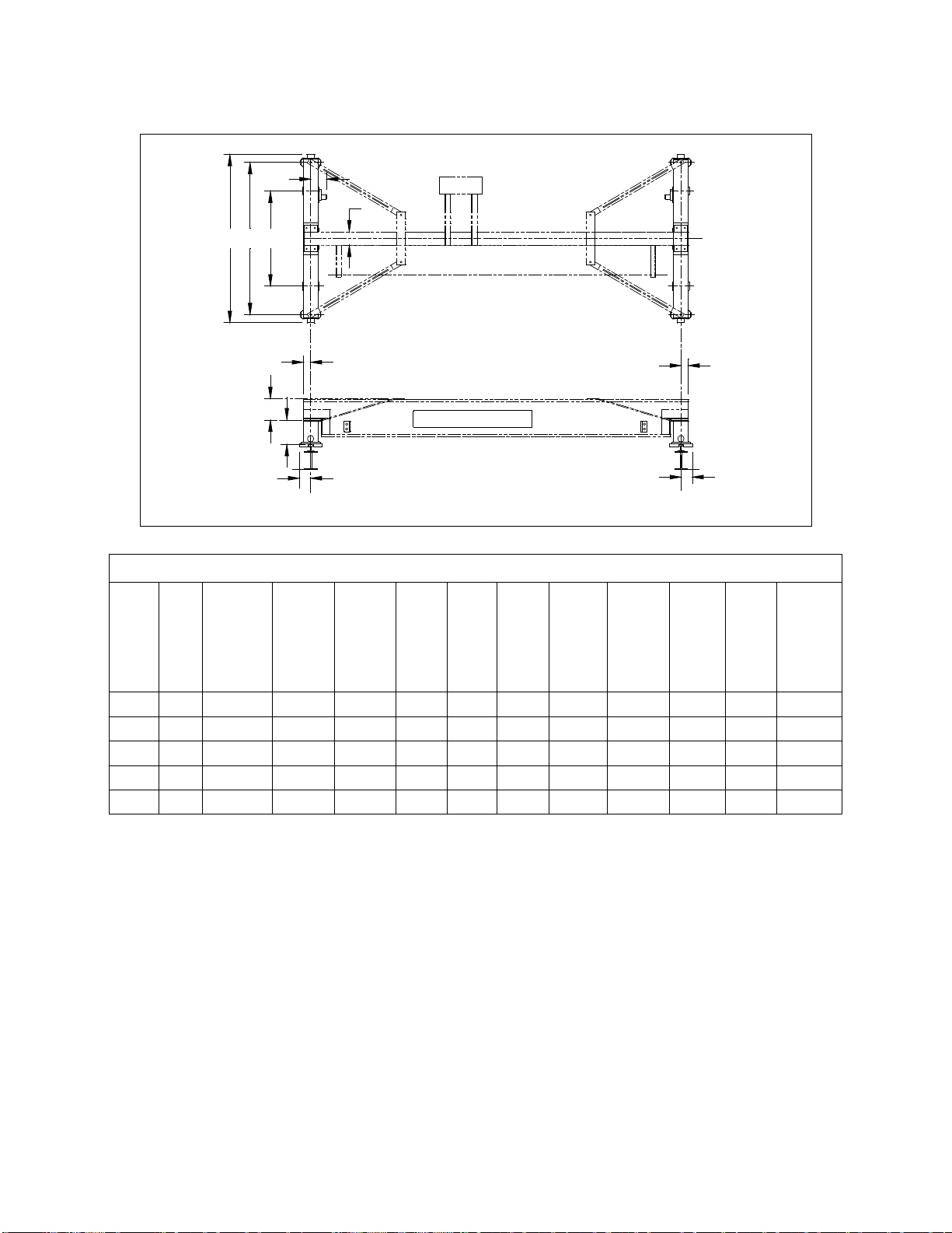
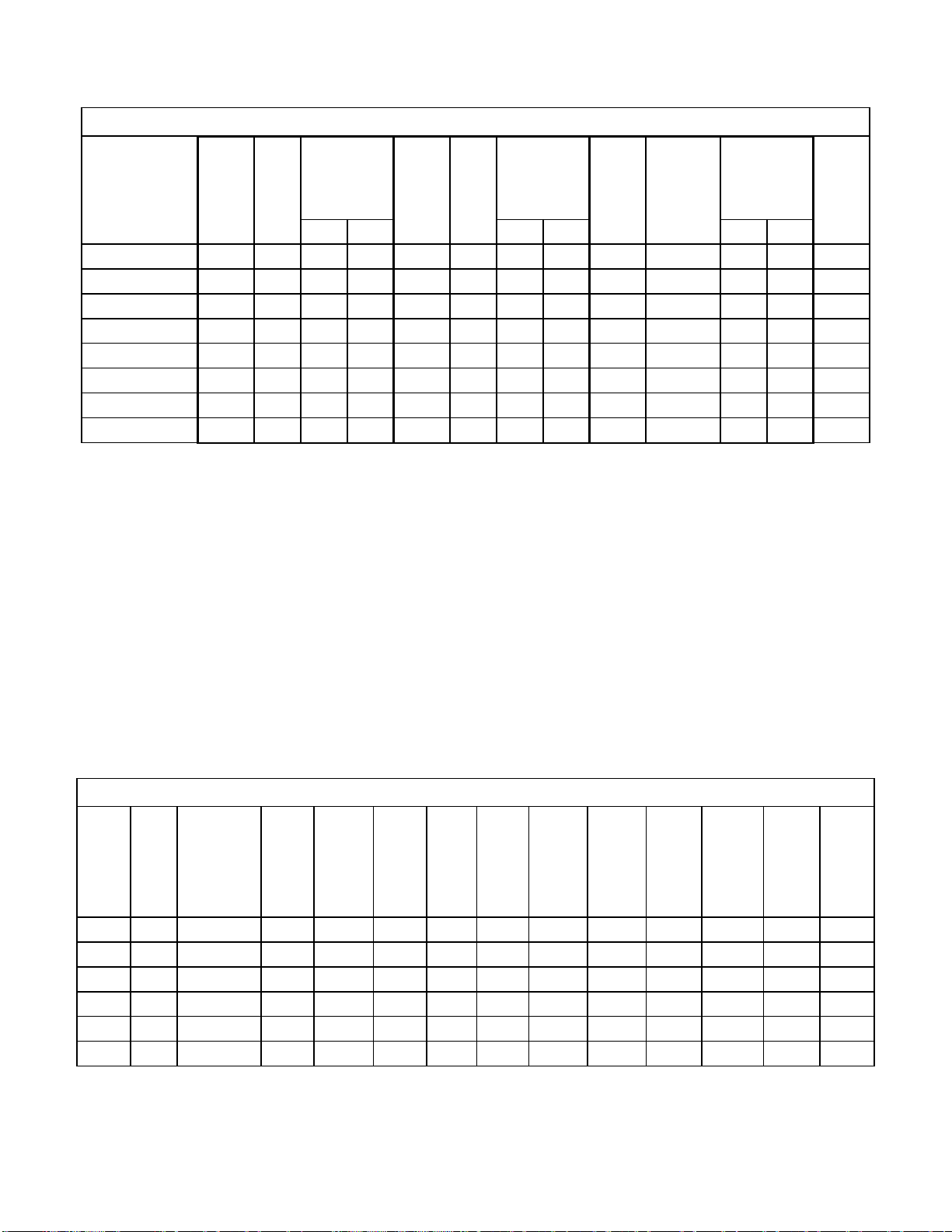
2.2 Specifications for Top Running End Trucks
BDA
EE
X
YHarrington Hoists, Inc.
X
F
AA
U
Figure 2-2 Top Running End Truck Dimensions
Top Running Push (Manual) End Trucks (Refer to Fig. 2-2)
Max.
Cap.
(Tons)
Max.
Span
(ft)
End Truck
Model # Wheel
Diameter
(in)
Sug.
Min.
Runway
Rail
(ACSE#)
A
Overall
Length
(in)
B
Roller
Base
(in)
D
Wheel
Base
(in)
E
Beam
Beyond
Span
(in)
U
Crane
Height
Above
End
Truck
(in)
X*
Width
Beyond
Span
(in)
Y
Top of
Rail to
Top of
End
Truck
(in)
End
Truck
Weight
(lbs./pr)
1 35 TP-3-0135 3.74 30 61 53 43 2.4 8.4** 4.6 7.1 242
1 45 TP-3-0145 3.74 30 98 90 80 2.4 8.4** 4.6 7.1 338
2 45 TP-3-0245 6.10 30 99 91 80 4.1 8.4** 4.6 7.1 454
3 35 TP-3-0335 6.10 30 62 54 43 4.1 8.4** 4.6 7.1 337
5 35 TP-3-0535 6.10 40 62 54 43 4.1 8.5 4.7 9.2 420
* Based on suggested minimum runway rail.
** 10.4” for cranes using a 10” beam
14
Top Running Geared End Trucks (Refer to Fig. 2-2)
Max.
Cap.
(Tons)
Max.
Span
(ft)
End Truck
Model # Wheel
Diameter
(in)
Suggested
Min.
Runway
Rail
(ACSE#)
A
Overall
Length
(in)
B
Roller
Base
(in)
D
Wheel
Base
(in)
E
Beam
Beyond
Span
(in)
J
Hand
Wheel
Offset
(in)
U
Crane
Height
Above
End
Truck
(in)
X*
Width
Beyond
Span
(in)
Y
Top of
Rail to
Top of
End
Truck
(in)
End
Truck
Weight
(lbs./
pr)
1 35 TG-3-0135 3.74 30 61 53 43 2.4 9.7 8.4** 4.6 7.1 264
1 50 TG-3-0150 3.74 30 98 90 80 2.4 9.7 8.4** 4.6 7.1 360
3 35 TG-3-0335 6.10 30 62 54 43 4.1 10.0 8.4** 4.6 7.1 359
3 50 TG-3-0350 6.10 30 99 91 80 4.1 10.0 8.4** 4.6 7.1 477
5 35 TG-3-0535 6.10 40 62 54 43 4.1 10.0 8.5 4.7 9.2 450
5 50 TG-3-0550 8.27 40 99 90 74 3.9 10.3 8.5 4.7 9.3 703
* Based on suggested minimum runway rail.
** 10.4” for cranes using a 10” beam

15
Top Running Motorized End Trucks (Refer to Fig. 2-2)
Max.
Cap.
(Tons)
Max.
Span
(ft)
End Truck
Model # Wheel
Diameter
(in)
Sug. Min.
Runway
Rail
(ACSE#)
A
Overall
Length
(in)
B
Roller
Base
(in)
D
Wheel
Base
(in)
E
Beam
Beyond
Span
(in)
U
Crane
Height
Above
End
Truck
(in)
X*
Width
Beyond
Span
(in)
Y
Top of
Rail to
Top of
End
Truck
(in)
AA
Span to
Motor End
(in)
1 35 TML/S/H/D-3-0135 3.74 30 61 53 43 2.4 8.4** 4.6 7.1 12.7 (L/S)
13.1 (H)
14.0 (D)
1 60 TML/S/H/D-3-0160 3.74 30 98 90 80 2.4 8.4** 4.6 7.1
3 35 TML/S/H/D-3-0335 6.10 30 62 54 43 4.1 8.4** 4.6 7.1 13.0 (L/S)
13.4 (H)
14.3 (D)
3 60 TML/S/H/D-3-0360 6.10 30 99 91 80 4.1 8.4** 4.6 7.1
5 35 TML/S/H/D-3-0535 6.10 40 62 54 43 4.1 8.5 4.7 9.2
5 60 TML/S/H/D-3-0560 8.27 40 99 90 74 3.9 8.5 4.7 9.3 15.0 (L/S/D)
15.4 (H)
10 35 TML/S/H/D-3-1035 9.84 60 63 53 37 6.0 12.5 6.3 11.3 17.4 (L/S/D)
18.7 (H)
10 60 TML/S/H/D-3-1060 9.84 60 100 90 74 6.0 12.5 6.3 11.3
* Based on suggested minimum runway rail.
** 10.4” for cranes using a 10” beam
16
Top Running Motorized End Truck - Gear Motors
End Truck
Model # Travel
Speed
(FPM)
Motor
Power
(Hp)
Ea. of
Two
Current
(AMPS) Ea. of
Two
Travel
Speed
(FPM)
Motor
Power
(Hp)
Ea. of
Two
Current
(AMPS) Ea. of
Two
Travel
Speed
(FPM)
Motor
Power (Hp)
Ea. of Two
Current
(AMPS) Ea. of
Two
Motor
End
Truck
Weight
(lbs./ pr)
230V 460V 230V 460V 230V 460V
TML/S/H/D-3-0135 40/80 0.33 1.6 1.0 120 0.5 2.1 1.3 80/20 0.33/0.08 1.6/1.1 0.9/0.8
325
TML/S/H/D-3-0160 40/80 0.33 1.6 1.0 120 0.5 2.1 1.3 80/20 0.33/0.08 1.6/1.1 0.9/0.8
422
TML/S/H/D-3-0335 40/80 0.33 1.6 1.0 120 0.5 2.1 1.3 80/20 0.33/0.08 1.6/1.1 0.9/0.8
421
TML/S/H/D -3-0360 40/80 0.33 1.6 1.0 120 0.5 2.1 1.3 80/20 0.33/0.08 1.6/1.1 0.9/0.8
538
TML/S/H/D-3-0535 40/80 0.33 1.6 1.0 120 0.5 2.1 1.3 80/20 0.33/0.08 1.6/1.1 0.9/0.8
512
TML/S/H/D-3-0560 40/80 0.50 2.1 1.3 120 1.0 3.3 2.0 80/20 0.50/0.13 2.0/1.5 1.2/0.9
739
TML/S/H/D-3-1035 40/80 1.00 3.3 2.0 120 2.0 5.8 3.1 80/20 1.00/0.25 3.7/2.1 2.3/1.4
883
TML/S/H/D-3-1060 40/80 1.00 3.3 2.0 120 2.0 5.8 3.1 80/20 1.00/0.25 3.7/2.1 2.3/1.4
1063
* Based on suggested minimum runway rail.
Speed Code
L - Designates the speed of 40 feet per minute
S - Designates the speed of 80 feet per minute
H - Designates the speed of 120 feet per minute
D - Designates the speed of dual speed 80/20 feet per minute
Product code derivation - example: TML/S/H/D-3-0135
T -Top Running
M - Motorized
L/S/H/D - Speed code - available in 40, 80, 120, or dual 80/20 feet per minute - choose desired speed
3 - Series number
01 - Capacity - 1 ton
35 - Maximum span - 35 feet
Max-E-Lift Top Running Geared End Trucks (Refer to Fig. 2-2)
Max.
Cap.
(Tons)
Max.
Span
(ft)
End Truck
Model # Wheel
Diamet
er (in)
Sug.
Min.
Runway
Rail
(ASCE#)
A
Overall
Length
(in)
B
Roller
Base
(in)
D
Wheel
Base
(in)
E
Beam
Beyond
Span
(in)
J
Hand
Wheel
Offset
(in)
K
Beam
Gauge
(in)
W *
Width
Beyond
Span
(in)
Y
Top of
Rail to
Top of
End
Truck
(in)
End
Truck
Weight
(lbs./pr)
1 35 MTG-3-0135 3.74 30 72 64 54 2.06 9.7 36 4.6 7.1 310
1 50 MTG-3-0150 3.74 30 111 103 93 2.06 9.7 36 4.6 7.1 411
3 35 MTG-3-0335 6.10 30 75 67 56 3.75 10.0 36 4.6 7.1 417
3 50 MTG-3-0350 6.10 30 112 104 93 3.75 10.0 36 4.6 7.1 538
5 35 MTG-3-0535 6.10 40 75 67 56 3.75 10.0 36 4.7 9.2 539
5 50 MTG-3-0550 8.27 40 112 103 87 3.50 10.3 36 4.7 9.3 789

17
Max-E-Lift Top Running Motorized End Trucks (Refer to Fig. 2-2)
Max.
Cap.
(Tons)
Max.
Span
(ft)
End Truck
Model # Wheel
Diameter
(in)
Sug. Min.
Runway
Rail
(ASCE#)
A
Overall
Length
(in)
B
Roller
Base
(in)
D
Wheel
Base
(in)
E
Beam
Beyond
Span
(in)
K
Beam
Gauge
(in)
W *
Width
Beyond
Span
(in)
Y
Top of
Rail to
Top of
End
Truck
(in)
AA
Span to
Motor End
(in)
1 35 MTML/S/H/D-3-0135 3.74 30 72 64 54 2.06 36 4.6 7.1 12.7 (L/S)
13.1 (H)
14.0 (D)
1 60 MTML/S/H/D-3-0160 3.74 30 111 103 93 2.06 36 4.6 7.1
3 35 MTML/S/H/D-3-0335 6.10 30 75 67 56 3.75 36 4.6 7.1 13.0 (L/S)
13.4 (H)
14.3 (D)
3 60 MTML/S/H/D-3-0360 6.10 30 112 104 93 3.75 36 4.6 7.1
5 35 MTML/S/H/D-3-0535 6.10 40 75 67 56 3.75 36 4.7 9.2
5 60 MTML/S/H/D-3-0560 8.27 40 112 103 87 3.50 36 4.7 9.3 15.0
(L/S/D)
15.4 (H)
10 35 MTML/S/H/D-3-1035 9.84 60 93 83 67 5.25 48 6.3 11.3 17.4
(L/S/D)
18.7 (H)
10 60 MTML/S/H/D-3-1060 9.84 60 113 103 87 5.25 48 6.3 11.3
Max-E Top Running Motorized End Truck - Gear Motors
End Truck Model # Travel
Speed
(FPM)
Motor
Power
(Hp)
Ea. of
Two
Current
(AMPS) Ea. of
Two
Travel
Speed
(FPM)
Motor
Power
(Hp)
Ea. of
Two
Current
(AMPS) Ea. of
Two
Travel
Speed
(FPM)
Motor
Power (Hp)
Ea. of Two
Current
(AMPS) Ea. of
Two
Motor
End
Truck
Weight
(lbs./pr)
230V 460V 230V 460V 230V 460V
MTML/S/H/D-3-0135 40/80 0.33 1.6 1.0 120 0.5 2.1 1.3 80/20 0.33/0.08 1.6/1.1
0.9/0.8
340
MTML/S/H/D-3-0160 40/80 0.33 1.6 1.0 120 0.5 2.1 1.3 80/20 0.33/0.08 1.6/1.1
0.9/0.8
441
MTML/S/H/D-3-0335 40/80 0.33 1.6 1.0 120 0.5 2.1 1.3 80/20 0.33/0.08 1.6/1.1
0.9/0.8
526
MTML/S/H/D -3-0360 40/80 0.33 1.6 1.0 120 0.5 2.1 1.3 80/20 0.33/0.08 1.6/1.1
0.9/0.8
647
MTML/S/H/D-3-0535 40/80 0.33 1.6 1.0 120 0.5 2.1 1.3 80/20 0.33/0.08 1.6/1.1
0.9/0.8
648
MTML/S/H/D-3-0560 40/80 0.50 2.1 1.3 120 1.0 3.3 2.0 80/20 0.50/0.13 2.0/1.5
1.2/0.9
818
MTML/S/H/D-3-1035 40/80 1.00 3.3 2.0 120 2.0 5.8 3.1 80/20 1.00/0.25 3.7/2.1
2.3/1.4
1105
MTML/S/H/D-3-1060 40/80 1.00 3.3 2.0 120 2.0 5.8 3.1 80/20 1.00/0.25 3.7/2.1
2.3/1.4
1202
18
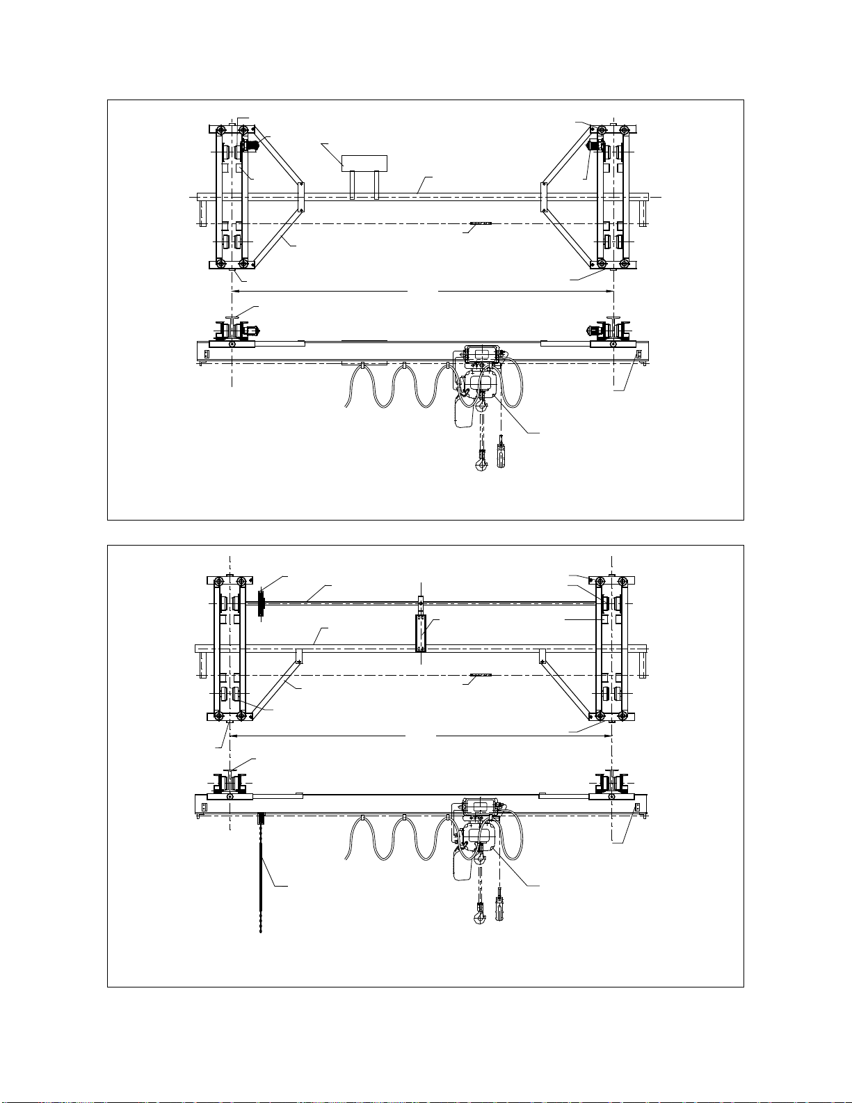
2.3 Component Names
RUNWAY BEAM
BRACES
STOP
DROP
SPAN
GUIDE WIRE
BRIDGE BEAM MOTOR
MOTOR BRIDGE CONTROL BOX
TYPICAL CRANE SYSTEM WITH UNDERHUNG MOTORIZED END TRUCKS
GUIDE ROLLER
BUMPER
GEARED WHEEL
TROLLEY STOP
END BRACKET
TYPICAL HOIST & TROLLEY
Figure 2-3
FOR DRIVE SHAFT
SUPPORT ASSEMBLIES
RUNWAY BEAM
BRACE
BRIDGE BEAM
SPAN
DRIVE SHAFT
HAND WHEEL
STOP
DROP
GUIDE WIRE
TYPICAL CRANESYSTEM WITH UNDERHUNG GEARED END TRUCKS
GUIDE ROLLER
GEARED WHEEL
END BRACKET
TROLLEY STOP
TYPICAL HOIST & TROLLEY
BUMPER
HAND CHAIN
PLAIN WHEEL
Figure 2-4

19
BRIDGE CONTROL BOX
GUIDE WIRE
MOTOR
BRACES
BRIDGE BEAM
END TRUCK
F
SPAN
TYPICAL CRANE SYSTEM WITH TOP RUNNING MOTORIZED END TRUCK
GUIDE ROLLERS
BUMPER
TROLLEY STOP
RUNWAY RAIL
RAIL SUPPORT STRUCTURE
Figure 2-5
BRACES
F
BRIDGE BEAM
END TRUCK
SPAN
FOR DRIVE SHAFT
SUPPORT ASSEMBLIES
DRIVE SHAFT
HAND WHEEL
GUIDE WIRE
TYPICALCRANE SYSTEM WITH TOP RUNNING GEARED END TRUCK
GUIDE ROLLERS
BUMPER
TROLLEY STOP
RAIL SUPPORT STRUCTURE
RUNWAY RAIL
HAND CHAIN
TYPICAL HOIST & TROLLEY
Figure 2-6

20
2.4 Bridge Crane Design Requirements -For proper selection of end trucks to meet your particular
needs, refer to the Harrington brochure “Choosing the Crane to Fit Your Needs” or our latest catalog.
2.4.1 CRANE RUNWAYS
Supporting Structure - Ensure that the supporting structure for the runways is adequate. If necessary
consult a professional that is qualified to evaluate the adequacy of the runway's supporting structure.
Installing a crane system on runways supported by inadequate supporting structure
could result in death or serious injury, and property damage.
Runway Design - Ensure that the runways meet the design requirements of the CMAA
Specification #70 or #74 whichever applies.
Runway Alignment - Ensure that the runways meet the runway alignment requirements of
CMAA Specification #70 or #74, whichever applies. For your convenience, Harrington has
provided these alignment criteria in Table 2-1 below.
Improper design, fabrication, or installation of crane runways could result in death or
serious injury, and property damage.
Table 2-1 CMAA Design Requirements
Item Overall Tolerance Maximum Rate
Of Change
Crane span (L) measured at crane wheel contact surface.
L < 50’
A = 3/16”
50’
< L < 100’
A = 1/4”
L > 100’
A = 3/8”
1/4” in 20’-0”
Straightness (B)
B = 3/8” 1/4” in 20’-0”
Elevation (C)
C =3 /8” 1/4” in 20’-0”
TOP RUNNING Transverse rail to rail elevation (D).
L < 50’
D = 3/16”
50’
< L < 100’
D = 1/4”
L > 100’
D = 3/8”
1/4” in 20’-0”
UNDER RUNNING Transverse girder to girder elevation (D).
Table of contents
Other KITO Truck manuals


