
Diagnostic Manual ( EMS) LCV MDI BSIII CRDe
Rev 01- Mar 14
All copyrights reserved by
The repair methods given by the manufacturer in this document are based on the technical specifications current at the time of release.
The methods may be modified as a result of changes introduced by the manufacturer in the production of the various component units
and accessories from which the vehicles are manufactured. The reproduction, translation, transmission, in part of whole of the present
document, are prohibited without the prior written consent of 2014 Mahindra Mahindra Ltd (Truck Bus Division)
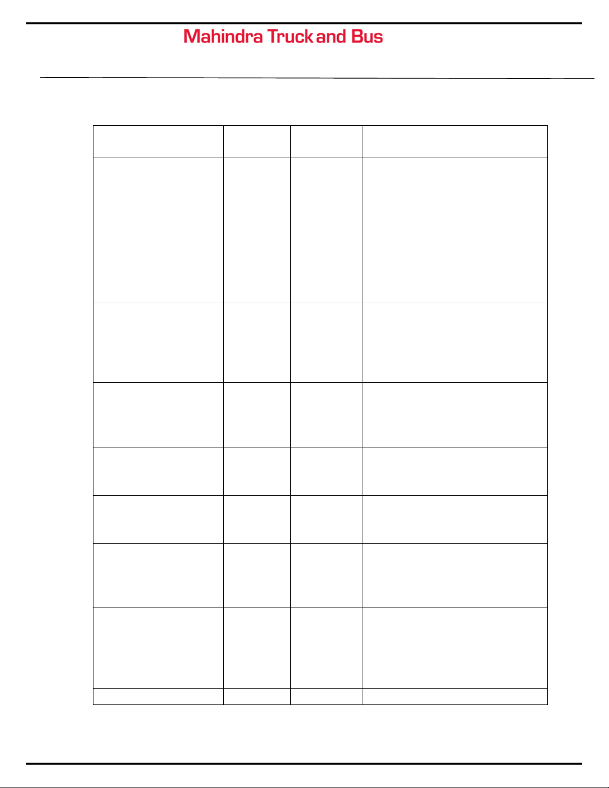
Injector
P1292 Measured resistance value equal to or less than the
calibrated threshold Value - INJECTOR Cyl 4
Measured resistance value equal to or greater than
the calibrated threshold value - INJECTOR Cyl 4
P1288 Measured resistance value equal to or less than the
calibrated threshold Value - INJECTOR Cyl 2
P1289 Measured resistance value equal to or greater than
the calibrated threshold value - INJECTOR Cyl 2
P0268C Incorrect or No I2C / I3C written on 1st Cylinder
P0268E Incorrect or No I2C / I3C written on 3rd Cylinder
P0268F Incorrect or No I2C / I3C written on 4th Cylinder
or No I2C / I3C written on 2nd Cylinder
Fuel Pump
P0627 Feed pump relay - Open circuit
P0628 Feed pump relay - Short circuit to Ground
Vehicle speed
sensor
P0501 Vehicle speed sensor output not consistant (erratic)
Vehicle speed sensor fault (speed too high)
P0502 Vehicle speed sensor fault (signal lost)
P0500 Vehicle speed fault(global)
Water in fuel
sensor
P2269 Water in fuel detected.
P2266 fault due to Short circuit
fault due to open circuit or VBAT
ECU
P0685 ECU Relay Struck Time
P1685 Supply Relay Open Circuit-unexpected.
P1603 Memory failure - in the coding region of the ECU.
P1604 Memory failure - in the calibration region of the
ECU.
P1605 Memory failure - in the RAM region of the ECU.
Battery P0562 Battery Voltage falls below 6 volts.
Battery Voltage falls below 18 volts.
P1560 Analogue to Digital Convertor Fault.
Sensor 5V
Sensor Supply voltage falls below the calibrated
value.
P0643 Sensor Supply voltage exceeds the calibrated value.
Analogue to Digital Convertor Fault.
P0652
Sensor Supply voltage falls below the calibrated value.
P0653
Sensor Supply voltage exceeds the calibrated value
P1651 Analogue to Digital Convertor Fault.


 Operator's manual")


