Kjellberg SmartFocus 300 User manual

Short Instruction Manual
Short instruction manual Smart Focus 300 with FC-300
- Safety
- Consumable change of the plasma torch
- Cutting charts
Art.-No.: .11.037.3002KBA
Pos: 1/ St euer mo dul e/---------------Seitenumbruch---------------@ 0\mod_1197390577023_19.docx@ 1454 @ @ 1

Short instruction manual Smart Focus 300 with FC-300
2
Pos: 2/Ü b ersc hrif te n/1/ KBA /KB A S martF oc us 3 00 mi t F C-300 @ 14\mod_1422606067950_19.docx@ 220043@ 1 @ 1
1 Short instruction manual Smart Focus 300 with FC-300
Short i nstr uction m anual S mart Fo cus3 200 with F C-300
Pos: 3.1 /Ü bers chr ift en/ 1.1/ Sic her heit _K BA @ 1\mod_1222090333431_19.docx@ 5425 @ 2@ 1
1.1 Safety
Pos: 3. 2/ Kurzb etrie bsanl eitung/ KBA ord nungsg emäß i nstall iert @ 1\mod_1222067978521_19.docx@ 5350@ @ 1
The short instruction manual is valid for the properly installed and with decrease protocol handed over
plasma cutting machine! The detailed safety references are to be inferred from the manual the point „safety"!
Pos: 3. 3/ Warn ung, Vors icht, V erbot, G ebot, Hin weis/ Warn ung (ora nge) / Rett ungsz eiche n(g rü n)/ War nu ng Öf fne n d es Ger ät es @ 0\mod_1199714392778_19.docx@2391 @ @1
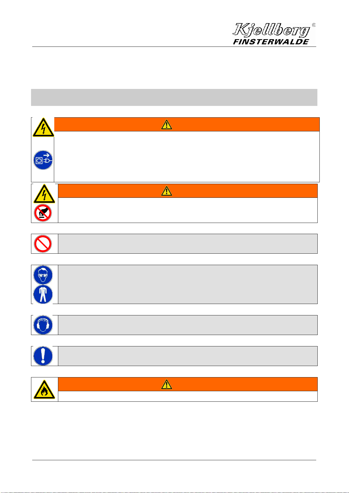
WARNING
Warning of dangerous electric voltage
Electric shock can be deadly. Further personal and material damages can result from impact.
Before opening (for example error search) or starting any maintenance and repair work
principally the power supply source has to be switched off and visibly disconnected from the
mains.
Opening the plasma unit may be carried out only under responsibility of a qualified
electrician!
Pos: 3.4 / Warn ung, Vor sich t, V erb ot, G eb ot, H inw eis/ War nu ng ( ora nge) / Ret tu ngsz eic hen ( grü n)/ ele ktri sch l eit en de T eil e @ 1\mod_1222078213884_19.docx@ 5365@ @ 1
WARNING
Do not touch under electrical voltage related conductive parts!
Pos: 3. 5/ Warn ung, Vors icht, V erbot, G ebot, Hin weis/ Verb otszeic hen (ro t)/Sic herh eitssc haltung en @ 1\mod_1222076180234_19.docx@ 5354@ @ 1
The safety circuits may not be suspended!
Pos: 3. 6/ Warn ung, Vors icht, V erbot, G ebot, Hin weis/ Gebots zeic hen (bla u)/Aug enbl endsch utz + Sch utzklei dung @ 1\mod_1222082302932_19.docx@ 5400@ @ 1
The operator has to wear an adequate eye shield and insulating protective clothing!
Pos: 3.7 / Warnung , Vorsi cht, V erbot, G ebot, Hin weis/ Gebotsz eic hen( bla u)/Ge hörsch utz @ 1\mod_1222079237524_19.docx@ 5395 @ @ 1
Suitable ear protection measures have to be taken in every case
(e.g. wearing of ear muffs or ear plugs)!
Pos: 3. 8/ Warn ung, Vors icht, V erbot, G ebot, Hin weis/ Gebots zeic hen (bla u)/ges undh eitssc hädlic he Stof fe @ 0\mod_1199803444549_19.docx@ 2517 @ @ 1
In any case the user of the unit installation has to carry out measurements of the
concentration of toxic substances to proof the effectiveness of the exhaust equipment!
Pos: 3. 9/ Warn ung, Vors icht, V erbot, G ebot, Hin weis/ Warn ung (ora nge) / Rett ungsz eiche n(g rün) /brenn bare St offe im Sc hneidb ereic h @ 1\mod_1222078297625_19.docx@ 5370@ @ 1
WARNING
Do not store flammable substances in the cutting area!
Pos: 3. 10 /Ste uerm odule---------------Sei ten um bruc h ---------------@ 0\mod_1197390577023_19.docx@ 1454@ @ 1

Short instruction manual Smart Focus 300 with FC-300
3
Pos: 3. 11 /War nung, Vors icht , Verbo t, Gebot, H inweis /War nung (or ange) / Re ttungsz eich en (grün) /U mgang mit G asfl aschen 1 @ 1\mod_1222078509612_19.docx@ 5375@ @1
WARNING
Place the cylinders in an upright position and lock it against tilting over!
Don't use damaged cylinders, pressure reducers and armatures!
Pos: 3. 12 /War nung, Vors icht , Verbo t, Gebot, H inweis /War nung (or ange) / Re ttungsz eich en (grün) /Ver schlei ßteile i n Berühr ung mit Sa uerstoff öl-u nd f ett frei (E xplos i onss ch utzs ich eru ng) @ 0\mod_1201005445751_19.docx@ 3177 @ @ 1
WARNING
All parts that come into contact with oxygen must be kept oil and grease free! When using
oxygen, the explosion protection for oxygen must be connected to the pressure-reducer
(protects against backfiring)!
Pos: 3. 13 /War nung, Vors icht , Verbo t, Gebot, H inweis /War nung ( ora ng e) / R et tung sz eich e n (g rün) /K ühl mit tel @ 1\mod_1222078951578_19.docx@ 5390@ @ 1
WARNING
Use only „Kjellfrost“ as coolant!
Pos: 3. 14 /War nung, Vors icht , Verbo t, Gebot, H inweis /Vorsi cht (g elb)/V orsic ht beim Umg ang mit Kj ellfr ost @ 0\mod_1199803848670_19.docx@ 2533@ @1
CAUTION
All details given on the label of the new anti-freezer have to be followed consequently!
•„Kjellfrost“ is injurious to health
•Don’t drink Kjellfrost
•Keep it away from food, drinks and fodder
•Always clean your hands before a break and after end of work
•Avoid the contact with eyes and skin
•Safety goggles recommended during filling
•Wear protection suit
•Wear gloves from Nitril or Viton (see safety data sheet)
•Immediately taking off soiled, watered clothes
•Special danger of skidding by run out or spilled "Kjellfrost"
•Keep away from children
Pos: 3. 15 /War nung, Vors icht , Verbo t, Gebot, H inweis /War nung (or ange) / Re ttungsz eich en (grün) /Erst eH ilfe M aßnah men @ 0\mod_1199802224840_19.docx@ 2497 @ @ 1
First aid
•after swallowing
Don’t bring up, clean the mouth, drink much water, open the window for fresh air and call the
doctor , present packing or label.
•after eye contact
Clean the eyes with much flowing water some minutes and call the doctor
•after skin contact
Quickly clean it with much water and soap
Pos: 3. 16 /Ste uerm odule---------------Sei ten um bruc h ---------------@ 0\mod_1197390577023_19.docx@ 1454@ @ 1

Short instruction manual Smart Focus 300 with FC-300
4
Pos: 3. 17 /Übers chri ften/1 .1/Ver schlei ßteil wechs el beim Br enner kopf @ 1\mod_1222065614778_19.docx@ 5330@ 2 @ 1
1.2 Consumable change at the plasma torch
Pos: 3. 18 /War nung, Vors icht , Verbo t, Gebot, H inweis /War nung (or ange) / Re ttungsz eich en (grün) /Ver schlei ßteil wechs el am Plas mabren ner -Plas maa nlag e von N etz tr en ne n @ 0\mod_1200055457147_19.docx@ 2774@ @ 1
WARNING
In order to change consumables, the plasma cutting system shall be switched OFF and
secured against any accidental start. An unauthorised start-up is prevented by e.g. pulling
out the key of the key-operated switch after switching off the plasma cutting system!
Pos: 3. 19 /War nung, Vors icht , Verbo t, Gebot, H inweis /Ver botsz eichen (r ot)/V erbot - ung eei gne te W er kzeug e f ür Brenn er wec hsel @ 0\mod_1199710363915_19.docx@ 2366@ @ 1
Under no circumstances pliers or other unsuitable tools have to be used for consumable
change, they entail inevitably the damage of the consumables, for example burr formation
and thereby malfunctions of the plasma torch.
Pos: 3. 20 /War nung, Vors icht , Verbo t, Gebot, Hin weis /Ge bo tsz eich en ( blau) / Ori ginal -Kjellberg-Vers chleiß teil e @ 0\mod_1202913276255_19.docx@ 3649@ @ 1
You are only allowed to use ORIGINAL Kjellberg spare parts and consumables!
The use of other manufacturer consumables leads to the loss of the warranty claim.
Pos: 3. 21 /War nung, Vors icht , Verbo t, Gebot, H inweis /War nung (or ange) / Re ttungsz eich en (grün) /Öl-u nd fett frei er Bren ner @ 0\mod_1199373195000_19.docx@ 2300@ @ 1
WARNING
All components and parts coming in touch with oxygen have to be kept free of oil and
grease!
This refers specially to the torch head and the consumables.
Pos: 3. 22 /War nung, Vors icht , Verbo t, Gebot, H inweis /Vorsi cht (g elb)/t echnol ogisc her Eins atz @ 1\mod_1222083106421_19.docx@ 5405@ @ 1
Use only exact the consumables which are destined for the technological operation!
Pos: 3. 23 /Ste uerm odule---------------Sei ten um bruc h ---------------@ 0\mod_1197390577023_19.docx@ 1454@ @ 1

Short instruction manual Smart Focus 300 with FC-300
5
Pos: 3. 24 /War nung, Vor sicht , Verbo t, Gebot , Hinwei s/Ge botsz eiche n(bl au)/ Schutz kapp e überpr üfen, Per Cut 2000/4 000 @ 13\mod_1413351612615_19.docx@ 207997@ @ 1
After screwing off the protective cap to replace the swirl gas cap without any further
replacement of consumables, the tightness of the nozzle cap must absolutely be checked
and, if required, tightened again before mounting the protective cap!
apply to plasma torch:
PerCut 2000
PerCut 4000
PerCut 4000 XS
Pos: 3. 25 /War nung, Vors icht , Verbo t, Gebot, H inweis /Gebo tszei chen (bl au)/A uf Volls tändig keit der V erschl eißtei le ach ten @ 0\mod_1200055848051_19.docx@2782 @ @ 1
Make sure that all wearing parts are complete and correct installed!
Especially the cooling tube has to be inserted. Other wise the cooling is ineffective and the
torch gets damaged.
No other parts as mentioned before have to be changed unauthorised on the plasma
machine torch.
A further opening of the torch from the front side is not possible.
Pos: 3. 26 /War nung, Vors icht , Verbo t, Gebot, H inweis /War nung (or ange) / Re ttungsz eich en (grün) /Dich theit d es Plasm abre nners @ 1\mod_1222083258875_19.docx@ 5409@ @ 1
You have to mind on tightness of the plasma torch after consumable change, coolant does
not leave!
Pos: 3. 27 /War nung, Vors icht , Verbo t, Gebot, H inweis /War nung (or ange) / Re ttungsz eich en (grün) /Entl adungs raum z wische n Katod e und D üse @ 1\mod_1222083434736_19.docx@ 5413 @ @ 1
The discharge chamber between cathode and nozzle has to be blown absolutely dry
(press tumbler switch “gas test” approx. 20 seconds - see “operation sequences”)
Pos: 3. 28 /Ste uerm odule---------------Sei ten um bruc h ---------------@ 0\ mod_1197390577023_19.docx@ 1454@ @ 1

Short instruction manual Smart Focus 300 with FC-300
6
Pos: 3. 29 /Über schr iften /1.1. 1/Pl asma-MaschinenbrennerPerCut2000/200A+ PerCut4000/4000A@ 13\mod_1413355095951_19.docx@ 208017@ 3 @ 1
1.2.1 Plasma machine torch PerCut 2000/2000A / PerCut 4000/4000A
Pos: 3.30 /Br en ner /P erCu t2 000 /4 000/ Aus -+Ei nbau VT-W echsel @ 13 \mod_1413296136320_19.docx@ 207971@ @ 1
Dismounting of used consumables
Before dismounting the consumables of the PerCut please insert the change head in the “Station for the
change heads” (see chapter “Dismantling of the change head”) and remove with the aid of compressed air
the coolant from the change head.
1.
Manually unscrew the protective cap (xx.07) together with the swirl gas cap (xx.06).
(Press out swirl gas cap from protective cap.)
2.
Unscrew nozzle cap (xx.05) by aid of a torch tool - PerCut 440-450* (60.02).
3.
Take out the nozzle (xx.04) together with the gas guide (xx.03) by aid of a torch tool - PerCut 440-450*
(60.02).
4.
Pull out the gas guide (xx.03) from the nozzle (xx.04) by aid of the specific wrench (60.03).
5.
Unscrew the cathode (xx.02) by aid of a torch tool - PerCut 440-450* (60.02).
6.
Remove the cooling tube (xx.01) using the socket wrench (60.01) when changing technology or
changing data set in accordance with the cutting data.
Mounting of new consumables
1.
Screw in the cooling tube (xx.01) by aid of a socket wrench (60.01).
2.
Tightly screw in the cathode (xx.02) by aid of a torch tool - PerCut 440-450* (60.02).
3.
Insert the gas guide (xx.03)
4.
Insert the nozzle (xx.04) into the torch head (see picture on next page). Turn the nozzle such that the
nozzle’s wide groove is positioned exactly above the oval opening in the torch head. Then insert the
nozzle until stop. Now the nozzle is locked and cannot be turned anymore.
5.
Position the nozzle cap (xx.05) by aid of a torch tool - PerCut 440-450* (60.02) and fasten hand tight
6.
Position the swirl gas nozzle (xx.06) and manually fasten with the protective cap (xx.07).
O-rings only need replacement in case of deformation or damage.
* The torch tool - PerCut 440-450 (60.02) is a multifunctional tool to:
•screw and unscrew the cathode by means of hexagon 11 mm,
•pull out the nozzle by means of the engraved notches 6 mm, 7 mm and 8 mm and
•screw and unscrew the nozzle cap by means of opening Ø 37 mm.
Pos: 3. 31 /Ste uerm odule---------------Sei ten um bruc h ---------------@ 0\mod_1197390577023_19.docx@ 1454@ @ 1

Short instruction manual Smart Focus 300 with FC-300
7
Pos: 3. 32 /Bren ner/P erCut 44 0/450 /Mont agehin weis Düs e @ 6\mod_1299572476000_19.docx@ 55454@ @ 1
Fig. 1: Insert the nozzle into the torch head
Pos: 3. 33 /Ste uerm odule---------------Sei ten um bruc h ---------------@ 0\mod_1197390577023_19.docx@ 1454@ @ 1

Short instruction manual Smart Focus 300 with FC-300
8
Pos: 3. 34 /Über schr ift en/1. 1/Bedi en- und AnzeigeelementederStromquelle@ 2\mod_1236339818423_19.docx@ 9395@ 2 @ 1
1.3 Operating and display elements of the power source
Pos: 3. 35 /Str omqu ellen/ Smart focus /Bedi en-undA nzeig eele mente @ 13 \mod_1412924542218_19.docx@ 207716@ @ 1
Fig. 2: Control and display elements
Pos: 3. 36 /Ste uerm odule---------------Sei ten um bruc h ---------------@ 0\mod_1197390577023_19.docx@ 1454@ @ 1

Short instruction manual Smart Focus 300 with FC-300
9
Pos: 3. 37 /Stromquellen/Smartfocus/Reihenfolgeder Bedienung @ 13\mod_1411632089106_19.docx@ 205208@ @ 1
Operation sequences
Check before starting the gas supply,corresponding to the point "connection of the gas supply" of gas
console.
1. Red emergency stop
device S3
“emergency stop” (1) Unlock the button by turning it in one direction.
2.
Key switch S1
“Mains ON" (2)
Turn the key switch to the position „I“.
switch to “PGC” when change consumables.
•Mains voltage is applied to the control transformer.
•Display of consumables at operation screen “data set parameter” of the PGC
(only for FlowControl).
3. Illuminated button
green S2 „PA ON" (3)
Activate the plasma unit with the illuminated push button.
Main transformer, fan, pump and control are switched on.
Inspection:
•The display screens appear for a short moment after starting the unit
following messages:
•
at the voltage display (17):
U-1 = device-no. example: device 1
SF = device typ example: Smart Focus
0 = voltage actual value example: 0 V
at the current display (16):
100 = software-version example: V 1.00
=max. current power source example: A
300 = current nominal value example: 300A
•
•green illuminated push button S2 “PA ON" (3):
lights
•LED signal lamp green H30 “Temperature OK" (9):
lights
•LED signal lamp green H29 “Coolant OK" (7):
lights
•An automated gas purging is started.
•LED signal lamp green H28 “Gas OK" (8):
lights
•LED signal lamp yellow H31 “Cumulative error" (13):
does not light
Unit is ready for operation!
4.
Selector switch S7
“technology” (4) Dial the technology range according cutting chart.
5. Operation gas
console
See instruction manual of corresponding gas console.
•Select the necessary plasma regime.
•Adjust plasma - and swirl gases according to the cutting charts.
6. potentiometer P5
"cutting current" (12) •Adjust the cutting current with the potentiometer.
•Look at the value shown at the current display (16).

Short instruction manual Smart Focus 300 with FC-300
10
7. potentiometer P7
“marking current” (15)
•Adjust the marking current with the potentiometer.
•Look at the value shown at the current display (16).
8. tumbler switch S2
“gas test” (5) Adjust the tumbler switch “Gas test”:
•press the tumbler switch “gas test” (5) at the power source or
•the switch/button “gas test” at the gas console
The gas test starts automatically:
•when unit becomes switched ON
•when changing gases of PGV
inspection:
•blowing out of the plasma torch
for example blowing out of the coolant residue after consumable change
•LED signal lamp yellow H31 "cumulative error" (13):
lights
•
The voltage display (17) shows “GAS” (6A5)
9. position the plasma
torch
•Bring the plasma torch in the start position.
•Adjust the ignition height according to the cutting chart.
Hole piercing occurs over the work piece.
Flying cutting is only possible with switch position 3 of the tumbler switch S7
“technology” (4).
10. plasma torch ON Plasma torch can be switched on through:
•the “torch ON”-signal of the CNC-control from the guiding system or
•pressing the ON-button at the remote control (FB)
Pilot arc ignition:
•LED signal lamp white H11“current flows” (10) :
lights
•after pilot arc contacts work piece, main arc ignites automatically
•LED signal lamp white H10 “main arc” (11) :
lights
11. plasma cutting Plasma cutting according to the cutting chart.
12. plasma torch OFF Plasma torch can be switched off through:
•discontinuation of the “torch ON”-signal of the CNC-control from the guiding
system or
•pressing the OFF-button at the remote control (FB)
Plasma arc extinguishes
13. plasma unit OFF Turn key switch S1 „Mains ON" (2) to
•Position „0 “
or
•Position „PGC“ (for consumable change)
The unit is switched off..
14. Red emergency stop
device S3
“emergency stop” (1)
Press the red emergency stop device S3 “emergency stop” (1).
All integrated components of the emergency stop circle are switched OFF, after
pressing the button.
Fig. 1: Operation sequences
Pos: 3. 38 /Ste uerm odule---------------Sei ten um bruc h ---------------@ 0\mod_1197390577023_19.docx@ 1454@ @ 1

Short instruction manual Smart Focus 300 with FC-300
11
Pos: 3. 39 /Über schr iften /1.1/ Bedie n- und Anz eig eelem ente der G asko nsole @ 2\mod_1236339916893_19.docx@ 9400@ 2@ 1
1.4 Operating and display elements of the gas console
Pos: 3. 40 /Gas konsol en/F lowC ontrol /Flo wcontr ol-300/ Bedi en-und A nzei ge elem ent e @ 1 3\mod_1415190545169_19.docx@ 210037@ @ 1
Fig. 3: Control and display elements FlowControl-300
Pos: 3. 41 /Gas konsol en/F lowC ontrol /Flo wcontr ol-300/ Bedi en-und Anz eigeel ement e, beschr . @ 13\mod_1415195665695_19.docx@ 210056@ @ 1

Short instruction manual Smart Focus 300 with FC-300
12
1 button „GASTEST"
2 display for gas control signal
3 display error
4 LCD Display
5 F1 button ”technology data
6 F2 button “to set selection”
7 F3 button “set change”
8 DEL button “delete button”
9 COPY button “new data set“
10 ENTER button “input confirmation“
11 PAGE button “changes display pages“
12 FIELD button “position change field“
13 CHAR-buttons “position change sign modification“
14 LED-Power - power supply ON
15 contrast adjustment display
16 hand wheel for parameter selection
17 option: binary data transmission to guiding system (X6)
18 serial interface RS-232 (X5)
19 switch of interfaces RS-485 – RS-232
20 connection to power source RS-485 (X4)
21 CAN1 signal connection to PGV (X2)
22 socket current supply PGC (X1)
23 store key of data set 0
24 store key of data set I
Pos: 3. 42 /Ste uerm odule---------------Sei ten um bruc h ---------------@ 0\ mod_1197390577023_19.docx@ 1454@ @ 1

Short instruction manual Smart Focus 300 with FC-300
13
Pos: 3. 43 /Über schr iften /1.1/ Einf üllen des K ühlmi ttels @ 0\mod_1197636336380_19.docx@ 1942@ 2 @ 1
1.5 Filling up the coolant
Pos: 3. 44 /Str omqu ellen/ Smart focus /Kühl mittel @ 13\mod_1411971846871_19.docx@ 205521@ @ 1
The coolant circuit is to be filled with "Kjellfrost -15 °C" (frost-resistant up to -15 °C) or "Kjellfrost -25 °C"
(frost-resistant up to -25 °C). In addition to frost protection, these coolants with specially developed corrosion
protection are also used for increasing the lifetime of the pump and seals as well as for increasing the
service life of the coolant channels of the plasma torch. Therefore, please use exclusively the coolant
„Kjellfrost“! The use of simple, standard antifreeze may cause the failure of the plasma system within a very
short time.
The volume of the coolant tank amounts to approx. 17 l. The filler neck (2) is at the rear panel of the power
source.
Please connect the plasma torch and fill in the coolant until it reaches the upper mark (max) of the filling level
indicator (1) before switching on the plasma system.
Warning: If the maximum filling quantity is exceeded, the coolant will exit the tank through the overflow and
run on the floor.
Switch on the plasma system and watch the filling level indicator.
After the pump has vented the coolant hoses and the plasma torch and the coolant level does not go down
any further, please refill „Kjellfrost“ up to the upper mark.
Changing the consumables and the plasma torch causes losses of the coolant. Therefore it is necessary to
control the coolant level regularly and to refill the coolant before it reaches the lower mark (min) of the filling
level indicator.
Regardless of the service life of the plasma system, the coolant has to be changed completely at least every
12 months.
Pos: 3. 45 /Ste uerm odule/--------------- Seite num bruc h ---------------@ 0\mod_1197390577023_19.docx@ 1454@ @ 1

Short instruction manual Smart Focus 300 with FC-300
14
Pos: 3. 46 /Über sc hrif ten /1.1 /Hi nw eise z ur F ehl ers uch e @ 0 \mod_1197633890412_19.docx@ 1844@ 2 @ 1
1.6 Information for trouble shooting
Pos: 3.47 / Str omq uell en/ Smar tfo cus /Hi nwei s e Fehl er such e @ 1 3\mod_1411713459011_19.docx@ 205227@ @ 1
error reason / solution
1.
After activating the key switch S1 “mains
ON“ (2) to position „I“ and switching on the
green illuminated push button S2 “PA ON“
(3), Pa does not switch ON
•emergency-stop device S3 “emergency stop“ (1) is
activated (reset switch)
•„emergency stop“ of CNC is activated
•link X102 (C3-C4) and X106 (1-2) for operation without
CNC
•cover plate on back wallof PA or door of PBA open
•control cable plasma torch not connected to X121/X122
•filling level in the coolant tank to low
2.
LED signal lamp yellow H31 "cumulative
error" (13) is ON and LED signal lamp
green H28 "Gas OK" (8) is OFF
•low pressure of selected gases (see cutting chart)
3.
LED signal lamp yellow H31 "cumulative
error" (13) is ON and LED signal lamp
green H29 "Coolant OK" (7) is OFF
•coolant flow < 3.0 l/min
•no or less coolant filled up
4.
LED signal lamp yellow H31 "cumulative
error" (13) is ON and LED signal lamp
green H30 "Temperature OK" (9) is OFF
•thermal overload on rectifier
cool down by running fan
5.
LED signal lamp white H11 “Pilot arc” (10)
OFF:
•no ignition
•check the pilot current
6.
LED signal lamp white H10 “Main arc” (11)
OFF: plasma cutting machine switches
OFF after ca. 10 s
•no cutting power, main power source OFF
•pilot arc time > 10 s;
•pilot arc without contact to workpiece
•no current flow to workpiece
-workpiece cable not connected
-ignition height not correct
Should coolant leak out, the cutting machine has to be switched off immediately, resolve the error and dry
the cutting machine!
Pos: 3.48 / Str omq uell en/ All ge meine s/Hi nw eis e zur Fehl ers uch e-2 @ 0\mod_1201793263097_19.docx@ 3479@ @ 1
The plasma sequence control of the plasma cutting system is displaying certain error codes, if during service
or operation errors are noticed. The current display indicates the corresponding error messages and
additionally the respective LED light.
The description of these errors and the rectification is given in the following chart:
Pos: 3. 49 /Ste uerm odule---------------Sei ten um bruc h ---------------@ 0\mod_1197390577023_19.docx@ 1454@ @ 1

Short instruction manual Smart Focus 300 with FC-300
15
Pos: 3. 50 /Str omqu ellen/ Smart focus /Fehl erta belle @ 13 \mod_1413204833342_19.docx@ 207796@ @ 1
current-
display relevance
LED-display cause end or fault clearance
ER 2
Error power
source
LED-signal lamp
yellow H31
“Cumulative error“
(13) lights and LED-
signal lamp yellow
H32 “Process error“
(14) flashes
current relay
K1.x “main source” or
K2 ”current flows” or
K3 ”current pilot
source flows“ is pulled
or voltage at the torch
without “torch ON”-
signal
remote control:
press “FB OFF”
stop “torch ON”
inform
the
service!
ER21
Transfer arc current relay K3
ER22
Main arc current relay K1
ER24
Pilot arc current relay K2
ER25
Actual current
detected Current flow without
ON signal
ER27
Fuse PBA defect check measuring
cable cathode voltage
and fuse F1 in PBA
ER28
Torch solenoid
valve Voltage of torch
solenoid valves not
OK
ER 3
Error torch LED-signal lamp
yellow H31
“cumulative error“ (13)
ON
current flow during
gas preflow
short circuit at the
torch
switch OFF unit, check
torch and consumables
ER31
Transfer arc Current relay K3
ER32
Main arc K1 Current relay K1
ER34
Pilot arc Currnt relay K2
ER35
Actual current
detected Current flow with ON
signal
ER 4
Pilot arc time LED-signal lamp
yellow H32 “Process
error“ (14)
pilot arc time
exceeded remote control:
press FB OFF
CNC: stop ON
ER 5
Ignition time LED-signal lamp
yellow H32 “Process
error“ (14)
HV ignition time
exceeded or no
ignition
remote control:
press FB OFF
CNC: stop ON
ER 6
Main arc inter-
ruption LED-signal lamp
yellow H32 “Process
error“ (14)
arc interruption during
cutting (main source) end after ca. 1 s

Short instruction manual Smart Focus 300 with FC-300
16
current-
display relevance
LED-display cause end or fault clearance
ER 8
Gas test period LED-signal lamp
yellow H32
“Process error“ (14)
max. time exceeded,
stop gas test and start
again if required
tumbler switch "gas test" OFF
ER 9
Pilot arc
interruption LED-signal lamp
yellow H32
“Process error“ (14)
plasma arc
interruption during
ignition (pilot source)
main arc is not formed
end after ca. 1 s
ER10
Communication
error LED-signal lamp
yellow H32
“Process error“ (14)
CAN communication
between
PGCPGV
interrupted
Control connection
PGC - PGV
ER43
Coolant error LED-signal lamp
yellow H31
“Cumulative error“
(13) ON and green
H29 “coolant OK”
(7) OFF
coolant quantity not
enough settle disturbances
ER51
Temperature
error LED-signal lamp
yellow H31
“Cumulative error“
(13) ON and green
H30 “temperature
OK” (9) OFF
high temperature settle disturbances
ER60
Sequence error LED-signal lamp
yellow H32
“Process error“ (14)
Error in the cutting
sequence
external release missed
ER70
Gas error
LED-signal lamp
yellow H31
“Cumulative error“
(13) ON and green
H28 “gas OK” (8)
OFF
gas missing check gas bottle if necessary
replace
ER71
gas missing at start of
power source open gas bottle
ER72
gas pressure too low check gas, start the power
source again
Pos: 3. 51 /Ste uerm odule/--------------- Seite num bruc h ---------------@ 0\mod_1197390577023_19.docx@ 1454@ @ 1
Pos: 3. 52 /Kur zbetr iebsa nleit ung/Kj ellb erg_A dress e @ 1\mod_1221824758746_19.docx@ 5326 @ @ 1
Kjellberg Finsterwalde Plasma und Maschinen GmbH
Germany • D - 03238 Finsterwalde • Oscar-Kjellberg-Str. 20
phone: +49 3531 500-0 • Fax: +49 3531 500-227
e-mail: plasma@kjellberg.de
Internet: www.kjellberg.de
Pos: 4/Ü b ersc hrif te n/Si cher hei tshi nw eis e_Pr od uktna me @ 1\mod_1222148646980_19.docx@ 5440@ @ 1
- Safety
Pos: 5/Ü b ers chri ft en/ Vers chl ei ßteil w ec hsel _Pr odu ktn ame @ 1\mod_1222148651251_19.docx@ 5445 @ @ 1
- Cons umabl e c hang e o f t he pl asm a tor c h
Pos:6/Überschriften/Schneiddatenhandbuch_Produktname@ 1\mod_1222088018302_19.docx@ 5421@ @ 1
- Cutti ng chart s
=== En de der Lis te für T extmar ke Inhal t= ==

Instruction Manual
- Power source Smart Focus 300
- Plasma gas control unit FlowControl-300
- Plasma machine torch PerCut 2000/2000A
PerCut 4000/4000A
- Plasma torch connection unit PBA-300
Art.-No.: .11.037.3002BA
Pos: 1/ All ge meine s/C op yrig ht un d In hal ts verz eic hnis @ 0\mod_1197373477322_19.docx@ 1421@ @ 1

General information
2
Copyright
The reproduction, distribution and utilization of this document as well as
the communication of its contents to others without express
authorization is prohibited. Offenders will be held liable for the payment
of damages. All rights reserved in the event of the grant of a patent,
utility model or design.
Subject to alterations.
Kjellberg Finsterwalde Plasma und Maschinen GmbH, 2015
Kjellberg Finsterwalde Plasma und Maschinen GmbH
Oscar-Kjellberg-Straße 20
DE - 03238 Finsterwalde
Tel.: +49 3531 500-0
Fax.: +49 3531 8510
E-Mail: plasma@kjellberg.de
Web: www.kjellberg.de

General information
3
Contents
1General information ...............................................................................................................................6
1.1 Warranty claim................................................................................................................................... 6
1.2 Standards and Directives................................................................................................................... 6
1.3 Information to the instruction manual - target groups........................................................................ 7
1.4 Plasma cutting as procedure............................................................................................................. 8
2Safety instructions...............................................................................................................................10
2.1 Explanation of the safety symbols................................................................................................... 10
2.2 Endangerment by high contact voltage ........................................................................................... 16
2.3 Working in environments with increased electric endangerment.................................................... 16
2.4 Endangerment by high voltage ignition ........................................................................................... 17
2.5 Endangerment by electromagnetic fields ........................................................................................ 18
2.6 Endangerment by heat and light radiation....................................................................................... 20
2.7 Endangerment by gases, smoke and types of dust ........................................................................ 21
2.8 Prevention of formation of oxyhydrogen.......................................................................................... 22
2.9 Endangerment by noise................................................................................................................... 23
2.10 Endangerment by spatter ................................................................................................................ 24
2.11 Handling of pressure reducer .......................................................................................................... 24
2.12 Handling of the coolant "Kjellfrost"................................................................................................... 25
3Maintenance..........................................................................................................................................27
3.1 Maintenance general ....................................................................................................................... 27
3.1.1 Intervals of maintenance.............................................................................................................. 27
3.1.2 Cleaning....................................................................................................................................... 28
3.1.2.1 Cleaning of the power source.............................................................................................. 28
3.1.2.2 Cleaning of the gas supply .................................................................................................. 28
3.1.3 Electrical revision......................................................................................................................... 29
3.1.4 Plasma torch................................................................................................................................ 30
3.2 Maintenance special........................................................................................................................ 31
3.2.1 Gas pressure test ........................................................................................................................ 31
3.2.2 Coolant system............................................................................................................................ 34
3.2.3 Preventive periodic maintenance - component change plan....................................................... 35
4Customer information on repair processing.....................................................................................36
5Disposal.................................................................................................................................................37
5.1 Disposal of the packing material...................................................................................................... 37
5.2 Disposal of the units after decommissioning................................................................................... 37
6Power source Smart Focus 300..........................................................................................................38
6.1 Technical data ................................................................................................................................. 39
6.2 Technical description....................................................................................................................... 40
6.2.1 Setup............................................................................................................................................ 40
6.2.2 Electronic control ......................................................................................................................... 41
6.2.3 Special parameters of the power source ..................................................................................... 41
6.3 Cutting technology........................................................................................................................... 42
6.4 Plasma marking............................................................................................................................... 43
6.5 Putting into operation....................................................................................................................... 44
6.5.1 Check, placement and transport.................................................................................................. 44

General information
4
6.5.2 Installation.................................................................................................................................... 46
6.5.2.1 Mains connection................................................................................................................. 46
6.5.2.2 Workpiece connection / current return line.......................................................................... 47
6.5.2.3 Connections at the rear panel of the power source............................................................. 50
6.6 Remote control FB (optional)........................................................................................................... 52
6.7 Filling up the coolant........................................................................................................................ 53
6.8 Operating and display elements...................................................................................................... 54
6.9 Cutting operation ............................................................................................................................. 60
6.10 Combination of the HiFocus with CNC-controls of the guiding systems and robots....................... 66
6.11 Multiple machine operation.............................................................................................................. 69
6.12 Switching regime of the power source............................................................................................. 70
6.12.1 Start by remote control FB (at commissioning) ....................................................................... 70
6.12.2 Start by CNC............................................................................................................................ 70
6.12.3 Start of Underwater Plasma Cutting (UWP Cutting)................................................................ 70
6.12.4 Start from CNC with special function "separate ignition signal" .............................................. 71
6.12.5 Start from CNC with special function "pre-impulse" ................................................................ 71
6.13 Protective facilities........................................................................................................................... 72
6.14 Information for trouble shooting....................................................................................................... 73
7Plasma gas control unit FlowControl-300 .........................................................................................76
7.1 Technical data ................................................................................................................................. 77
7.2 Technical description....................................................................................................................... 78
7.2.1 Operation ..................................................................................................................................... 79
7.2.2 Operation screen "start screen“................................................................................................... 80
7.2.3 Operation screen "Cutting".......................................................................................................... 81
7.2.4 Operation screen "record parameters"........................................................................................ 85
7.2.5 Operation screen "data survey"................................................................................................... 87
7.2.6 Operation screen "Configuration data"........................................................................................ 88
7.2.7 Operation screen "Support"......................................................................................................... 91
7.2.8 Selection of data sets for the cutting and marking process......................................................... 91
7.2.8.1 Manual selection of cutting data at the PGC 3.................................................................... 91
7.2.8.2 Selection of a data set of the PGC ...................................................................................... 92
7.2.8.3 Fast data set selection by using the keys "0" and "I"........................................................... 93
7.2.8.4 Safe of user data set............................................................................................................ 95
7.2.8.5 Delete of data sets............................................................................................................... 95
7.2.8.6 Preselection of gas parameters from the external control................................................... 96
7.3 Operating and display elements...................................................................................................... 98
7.4 Connection of the plasma gas valve unit PGV.............................................................................. 100
7.5 Connection of the gas hoses between plasma gas console and PBA.......................................... 102
7.6 Connection of the gas supply........................................................................................................ 102
7.6.1 Plasma gases ............................................................................................................................ 103
7.7 Assembly of clamping ring connections ........................................................................................ 105
7.7.1 Initial assembly .......................................................................................................................... 105
7.7.2 Dismantling................................................................................................................................ 105
7.7.3 Reassembly............................................................................................................................... 106
8Plasma machine torch PerCut 2000/2000A / PerCut 4000/4000A..................................................107
8.1 Technical data ............................................................................................................................... 108
8.2 Technical description..................................................................................................................... 110
This manual suits for next models
2
Table of contents
Other Kjellberg Welding System manuals