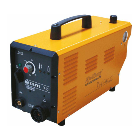
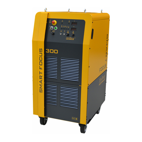
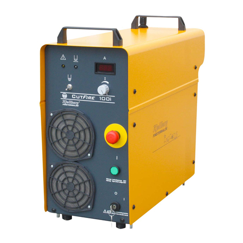
Kjellberg PerCut 200 User manual

Short instruction manual HiFocus 161i with PGE 3-161
P
os: 1.1 /Überschrif ten/1/KBA/KBA HiFo 161i + PGE 3-161 @ 12\ mod_1385361813652_19. doc @ 192112 @ 1 @ 1
1 Short instruction manual HiFocus 161i with PGE 3-161
S
P
hort instruction manual HiFocus 161i with PGE 3-161
os: 1.2 /Überschri ften/1.1/Sicher heit_KBA @ 1\mod_12220903334 31_19.doc @ 5425 @ 2 @ 1
1.1 Safety
P
os: 1.3 /Kurzbetriebsan leitung/KBA ordnung sgemäß installiert @ 1\ mod_1222067978521_19. doc @ 5350 @ @ 1
The short instruction manual is valid for the properly installed and with decrease protocol handed over
plasma cutting machine! The detailed safety references are to be inferred from the manual the point „safety"!
P
os: 1.4 /Warnung, Vorsicht, Verbot, Gebot, Hin weis/Warnung (orange) / Rettungszeichen (grün)/W arnung Öffnen des Gerätes @ 0\ mod_1199714392778_19. doc @ 2391 @ @ 1
WARNING
Warning of dangerous electric voltage
Electric shock can be deadly. Further personal and material damages can result from impact.
Before opening (for example error search) or starting any maintenance and repair work
principally the power supply source has to be switched off and visibly disconnected from the
mains.
Opening the plasma unit may be carried out only under responsibility of a qualified
electrician!
P
os: 1.5 /Warnung, Vorsicht, Verbot, Gebot, Hin weis/Warnung (orange) / Rettungszeichen (grün)/ elektrisch leitende Teile@ 1\mod_1222078213884_19. doc @ 5365 @ @ 1
WARNING
Do not touch under electrical voltage related conductive parts!
P
os: 1.6 /Warnung, Vorsic ht, Verbot, Gebot, Hinweis/Verbotszeic hen( rot)/Sicherheitsscha ltungen @ 1\mod_1222076180234_1 9.doc @ 5354@ @ 1
The safety circuits may not be suspended!
P
os: 1.7 /Warnung, Vorsicht, Verbot, Gebot, Hin weis/Gebotszeichen ( blau)/Augenblendsc hutz + Schutzkleidung @ 1\ mod_122208230293 2_19.doc @ 5400 @ @ 1
The operator has to wear an adequate eye shield and insulating protective clothing!
Pos: 1.8 /Warnung, Vorsic ht, Verbot, Gebot, Hinweis/Gebotszeic hen( blau)/Gehörschutz @ 1\mod_122207 9237524_19.doc @ 5395 @ @ 1
Suitable ear protection measures have to be taken in every case
(e.g. wearing of ear muffs or ear plugs)!
P
os: 1.9 /Warnung, Vorsicht, Verbot, Gebot, Hin weis/Gebotszeichen (blau) /gesundheitssc hädliche Stoffe @ 0\ mod_1199803444549_19.d oc @ 2517 @ @ 1
In any case the user of the unit installation has to carry out measurements of the
concentration of toxic substances to proof the effectiveness of the exhaust equipment!
P
os: 1.10 /Warnung, Vorsic ht, Verbot, Gebot, Hinweis/Warnung (orange) / Rettung szeichen (grün)/brennbar eStoff ei mSc hneidbereich @ 1\mod_1222078 297625_19.doc @ 5370 @ @ 1
WARNING
Do not store flammable substances in the cutting area!
Pos: 1.11 /----- ---------- Seitenumbruc h ----------- ---- @ 0\mod_1197390577023_19. doc @ 1454 @ @ 1
2

Short instruction manual HiFocus 161i with PGE 3-161
os: 1.12 /Warnung, Vorsicht, Verbot, Gebot, Hin weis/Warnung (orange) / Rettungszeichen (grün)/ Umgang mit Gasflaschen 1 @ 1\ mod_1222078509612_19. doc @ 5375 @ @ 1P
WARNING
Place the cylinders in an upright position and lock it against tilting over!
Don't use damaged cylinders, pressure reducers and armatures!
P
os: 1.13 /Warnung, Vorsicht, Verbot, Gebot, Hin weis/Warnung (orange) / Rettungszeichen (grün)/ Verschleißteile in Ber ührung mit Sauerstoff öl- und fettfrei (Explosi onsschutzsicher ung) @ 0\mod_12010054457 51_19.doc @ 3177 @ @ 1
WARNING
All parts that come into contact with oxygen must be kept oil and grease free! When using
oxygen, the explosion protection for oxygen must be connected to the pressure-reducer
(protects against backfiring)!
P
os: 1.14 /Warnung, Vorsic ht, Verbot, Gebot, Hinweis/Warnung (orange) / Rettung szeichen (grün)/Kühlmit tel@ 1\mod _1222078951578_19. doc @ 5390 @ @1
WARNING
Use only „Kjellfrost“ as coolant!
P
os: 1.15 /Warnung, Vorsic ht, Verbot, Gebot, Hinweis/Vorsicht (gelb) /Vorsicht beim Umgang mit Kjellfrost @ 0\mod_1199803 848670_19.doc @2533 @ @ 1
CAUTION
All details given on the label of the new anti-freezer have to be followed consequently!
„Kjellfrost“ is injurious to health
Don’t drink Kjellfrost
Keep it away from food, drinks and fodder
Always clean your hands before a break and after end of work
Avoid the contact with eyes and skin
Safety goggles recommended during filling
Wear protection suit
Wear gloves from Nitril or Viton (see safety data sheet)
Immediately taking off soiled, watered clothes
Special danger of skidding by run out or spilled "Kjellfrost"
Keep away from children
P
os: 1.16 /Warnung, Vorsicht, Verbot, Gebot, Hin weis/Warnung (orange) / Rettungszeichen (grün)/ Erste Hilfe Maßnahmen @ 0\mod _1199802224840_19. doc @ 2497 @ @ 1
First aid
after swallowing
Don’t bring up, clean the mouth, drink much water, open the window for fresh air and call the
doctor , present packing or label.
after eye contact
Clean the eyes with much flowing water some minutes and call the doctor
after skin contact
Quickly clean it with much water and soap
Pos: 1.17 /----- ---------- Seitenumbruc h ----------- ---- @ 0\mod_1197390577023_19. doc @ 1454 @ @ 1
3

Short instruction manual HiFocus 161i with PGE 3-161
os: 1.18 /Überschri ften/1.1/Verschleißt eilwechsel beim Brennerk opf @ 1\mod_122206561477 8_19.doc @ 5330 @ 2 @ 1P
1.2 Consumable change at the plasma torch
P
os: 1.19 /Warnung, Vorsic ht, Verbot, Gebot, Hinweis/Warnung (orange) / Rettung szeichen (grün)/Versc hleißteilwechsel am Plasmabrenn er -Plasmaanlage von Ne tztr ennen @ 0\mod_1200055457 147_19.doc @ 2774 @ @ 1
WARNING
In order to change consumables, the plasma cutting system shall be switched OFF and
secured against any accidental start. An unauthorised start-up is prevented by e.g. pulling
out the key of the key-operated switch after switching off the plasma cutting system!
P
os: 1.20 /Warnung, Vorsic ht, Verbot, Gebot, Hinweis/Verbotszeic hen( rot)/Verbot - ungeeignete Werkzeuge für B rennerwechsel @ 0\mod_119971036391 5_19.doc @ 2366 @ @ 1
Under no circumstances pliers or other unsuitable tools have to be used for consumable
change, they entail inevitably the damage of the consumables, for example burr formation
and thereby malfunctions of the plasma torch.
P
os: 1.21 /Warnung, Vorsic ht, Verbot, Gebot, Hinweis/Gebotszeic hen( blau)/Original-Kje llberg-Verschleißtei le@ 0\mod_1 202913276255_19.doc @ 3649 @ @1
You are only allowed to use ORIGINAL Kjellberg spare parts and consumables!
The use of other manufacturer consumables leads to the loss of the warranty claim.
P
os: 1.22 /Warnung, Vorsic ht, Verbot, Gebot, Hinweis/Warnung (orange) / Rettung szeichen (grün)/Öl-und fettf reier Brenner @ 0\mod_1199373195000_19. doc @ 2300 @ @ 1
WARNING
All components and parts coming in touch with oxygen have to be kept free of oil and
grease!
This refers specially to the torch head and the consumables.
P
os: 1.23 /Warnung, Vorsic ht, Verbot, Gebot, Hinweis/Vorsicht (gelb) /technologischer Einsa tz@ 1\mod_122 2083106421_19.doc @ 5405 @ @ 1
Use only exact the consumables which are destined for the technological operation!
Pos: 1.24 /----- ---------- Seitenumbruc h ----------- ---- @ 0\mod_1197390577023_19. doc @ 1454 @ @ 1
4

Short instruction manual HiFocus 161i with PGE 3-161
os: 1.25 /Warnung, Vorsic ht, Verbot, Gebot, Hinweis/Gebotszeic hen( blau)/Schutzkappe überpr üfen, PerCut210 @ 5\mod_12888731919 68_19.doc @ 41226 @ @ 1P
After screwing off the protective cap to replace the swirl gas cap without any further
replacement of consumables, the tightness of the nozzle cap must absolutely be checked
and, if required, tightened again before mounting the protective cap!
apply to plasma torch:
PerCut 200 / 210A / 210M
PerCut 201 / 211A / 211M
P
os: 1.26 /Warnung, Vorsic ht, Verbot, Gebot, Hinweis/Gebotszeic hen( blau)/Auf Vollständigkei tder Ver schleißteile achten @ 0\mod_1200 055848051_19.doc @ 2782 @ @ 1
Make sure that all wearing parts are complete and correct installed!
Especially the cooling tube has to be inserted. Other wise the cooling is ineffective and the
torch gets damaged.
No other parts as mentioned before have to be changed unauthorised on the plasma
machine torch.
A further opening of the torch from the front side is not possible.
P
os: 1.27 /Warnung, Vorsic ht, Verbot, Gebot, Hinweis/Warnung (orange) / Rettung szeichen (grün)/Dic htheitdes P lasmabrenners @ 1\mod_12220832588 75_19.doc @ 5409 @ @ 1
You have to mind on tightness of the plasma torch after consumable change, coolant does
not leave!
P
os: 1.28 /Warnung, Vorsic ht, Verbot, Gebot, Hinweis/Warnung (orange) / Rettung szeichen (grün)/Entladu ngsraum zwischen Katode und Düse @ 1\mod_122 2083434736_19.doc @5413 @ @ 1
The discharge chamber between cathode and nozzle has to be blown absolutely dry
(press tumbler switch “gas test” approx. 20 seconds - see “operation sequences”)
Pos: 1.29 /----- ---------- Seitenumbruc h ----------- ---- @ 0\mod_1197390577023_19. doc @ 1454 @ @ 1
5

Short instruction manual HiFocus 161i with PGE 3-161
os: 1.30 /Überschri ften/1.1.1/Plasmam aschinenbrenner Per Cut 210 @ 5\mod_128888294958 2_19.doc @ 41346 @ 3 @ 1P
1.2.1 Plasma machine torch PerCut 200 / 210A / 210M
P
os: 1.31 /Brenner/ PerCut 200/210/Verschl eißteilübersic ht PerCut 210 @ 5\mod_12888734 32771_19.doc @ 41237 @ @ 1
Dismounting of used consumables
1. Manually unscrew the protective cap (xx.07) together with the swirl gas cap (xx.06).
(Press out swirl gas cap from protective cap.)
2. Unscrew nozzle cap (xx.05) by aid of a torch tool - PerCut 440-450* (60.02).
3. Take out the nozzle (xx.04) together with the gas guide (xx.03) by aid of a
torch tool - PerCut 440-450* (60.02).
4. Pull out the gas guide (xx.03) from the nozzle (xx.04) by aid of the specific wrench (60.03).
5. Unscrew the cathode (xx.02) by aid of a torch tool - PerCut 440-450* (60.02).
6. Remove the cooling tube (xx.01) using the socket wrench (60.01) when changing technology or
changing data set in accordance with the cutting data.
Mounting of new consumables
1. Screw in the cooling tube (xx.01) by aid of a socket wrench (60.01).
2. Tightly screw in the cathode (xx.02) by aid of a torch tool - PerCut 440-450* (60.02).
3. Insert the gas guide (xx.03)
4. Insert the nozzle (xx.04) into the torch head (see picture on next page). Turn the nozzle such that the
nozzle’s wide groove is positioned exactly above the oval opening in the torch head. Then insert the
nozzle until stop. Now the nozzle is locked and cannot be turned anymore.
5. Position the nozzle cap (xx.05) by aid of a torch tool - PerCut 440-450* (60.02) and fasten hand tight
6. Position the swirl gas nozzle (xx.06) and manually fasten with the protective cap (xx.07).
O-rings only need replacement in case of deformation or damage.
* The torch tool - PerCut 440-450 (60.02) is a multifunctional tool to:
screw and unscrew the cathode by means of hexagon 11 mm,
pull out the nozzle by means of the engraved notches 6 mm, 7 mm and 8 mm and
screw and unscrew the nozzle cap by means of opening Ø 37 mm.
Pos: 1.32 /----- ---------- Seitenumbruc h ----------- ---- @ 0\mod_1197390577023_19. doc @ 1454 @ @ 1
6

Short instruction manual HiFocus 161i with PGE 3-161
os: 1.33 /Überschri ften/1.1.1/Plasma- Maschinenbrenner PerCut 201 / 211A / 211M @ 8\mod_13354345 66622_19.doc @ 153764 @ 3 @ 1P
1.2.2 Plasma machine torch PerCut 201 / 211A / 211M
P
os: 1.34 /Brenner/ PerCut201/211/VT-Üb ersicht +Aus-u.Ei nbau @ 8\mod_1335432657792_ 19.doc @ 153656 @ @ 1
Dismounting of used consumables
Before dismounting the consumables of the PerCut 211A please insert the change head in the “Station for
the change heads” (see chapter “Dismantling of the change head”) and remove with the aid of compressed
air the coolant from the change head.
1. Manually unscrew the protective cap (xx.07) together with the swirl gas cap (xx.06).
(Press out swirl gas cap from protective cap.)
2. Unscrew nozzle cap (xx.05) by aid of a torch tool - PerCut 440-450* (60.02).
3. Take out the nozzle (xx.04) together with the gas guide (xx.03) by aid of a torch tool - PerCut 440-450*
(60.02).
4. Pull out the gas guide (xx.03) from the nozzle (xx.04) by aid of the specific wrench (60.03).
5. Unscrew the cathode (xx.02) by aid of a torch tool - PerCut 440-450* (60.02).
6. Remove the cooling tube (xx.01) using the socket wrench (60.01) when changing technology or
changing data set in accordance with the cutting data.
Mounting of new consumables
1. Screw in the cooling tube (xx.01) by aid of a socket wrench (60.01).
2. Tightly screw in the cathode (xx.02) by aid of a torch tool - PerCut 440-450* (60.02).
3. Insert the gas guide (xx.03)
4. Insert the nozzle (xx.04) into the torch head (see picture on next page). Turn the nozzle such that the
nozzle’s wide groove is positioned exactly above the oval opening in the torch head. Then insert the
nozzle until stop. Now the nozzle is locked and cannot be turned anymore.
5. Position the nozzle cap (xx.05) by aid of a torch tool - PerCut 440-450* (60.02) and fasten hand tight
6. Position the swirl gas nozzle (xx.06) and manually fasten with the protective cap (xx.07).
O-rings only need replacement in case of deformation or damage.
* The torch tool - PerCut 440-450 (60.02) is a multifunctional tool to:
screw and unscrew the cathode by means of hexagon 11 mm,
pull out the nozzle by means of the engraved notches 6 mm, 7 mm and 8 mm and
screw and unscrew the nozzle cap by means of opening Ø 37 mm.
Pos: 1.35 /----- ---------- Seitenumbruc h ----------- ---- @ 0\mod_1197390577023_19. doc @ 1454 @ @ 1
7

Short instruction manual HiFocus 161i with PGE 3-161
os: 1.36 /Brenner/ PerCut 440/450/Montagehi nweis Düse @ 6\mod_1299572 476000_19.doc @ 55454 @ @ 1P
Fig. 1.: Insert the nozzle into the torch head
Pos: 1.37 /----- ---------- Seitenumbruc h ----------- ---- @ 0\mod_1197390577023_19. doc @ 1454 @ @ 1
8

Short instruction manual HiFocus 161i with PGE 3-161
os: 1.38 /Überschri ften/1.1/Bedien- und Anz eigeelemente der Stromquelle @ 2\mod_12363398184 23_19.doc @ 9395 @ 2 @ 1P
1.3 Operating and display elements of the power source
P
os: 1.39 /Stromque llen/HiFocus/HiFo161i /Bedien- und Anzeigee lemente @ 6\mod_1305094 057624_19.doc @ 61750 @ @ 1
Fig. 2.: Control- and display elements
Pos: 1.40 /----- ---------- Seitenumbruc h ----------- ---- @ 0\mod_1197390577023_19. doc @ 1454 @ @ 1
9

Short instruction manual HiFocus 161i with PGE 3-161
10
os: 1.41 /Stromque llen/HiFocus/HiFo161i /Reihenfolge der Bedienung@ 6\mod_1305116445455_19. doc @ 61848 @ @ 1P
Operation sequences
1. red mushroom button
S3 “emergency stop"
(1) Unlock the button by turning it in one direction.
2. Key switch S1
“Mains ON" (2) Turn the key switch to the position „I“.
switch to “PGC” when change consumables.
Mains voltage is applied to the control transformer.
Display of consumables at operation screen “Record parameter” of the PGC
(only for FlowControl).
3. green illuminated
push button S2
“readiness for
operation" (3)
Activate the plasma unit with the illuminated push button.
Main transformer, pump and control are switched on.
Inspection:
The display screens appear for a short moment after starting the unit following
messages:
at the voltage display (20):
U-1 = device-no. example: device 1
0 =voltage actual value example: 0 V
at the current display (21):
705 =software-version example: V 7.05
160 =current nominal value example: 160 A
green illuminated push button S2 “readiness of operation" (3):
lights
LED signal lamp green “Temperature power source o.k." (15):
lights
LED signal lamp green “Cooling circuit o.k." (13):
lights
“gas test“ starts automatically
LED signal lamp green “Gas supply o.k." (14):
lights
LED signal lamp „Cumulative error" (18):
is off
Unit ready for operation!
4. Selector switch S5
“technology range” (4) Dial the technology range according cutting chart.
5. Operation gas
console See instruction manual of corresponding gas console.
Select the necessary plasma regime.
Adjust plasma - and swirl gases according to the cutting charts.
6. potentiometer "cutting
current" (9) Adjust the cutting current with the potentiometer.
Look at the value shown at the current display (21).
7. potentiometer
“marking current” (8) applies only to power sources and gas consoles which support the marking:
Adjust the marking current with the potentiometer.
Look at the value shown at the current display (21).
8. potentiometer
“current reduction”
(10)
current reduction at signal „corner“ from CNC:
Activate the tumbler switch „gas test“ (6) to the upper position
and adjust current reduction with the potentiometer:
maximum value: 30 % of nominal current.
Look at the value shown at the current display (21).

Short instruction manual HiFocus 161i with PGE 3-161
11
9. Potentiometer „Down
slope“ (11) activate tumbler switch “down slope-time“ (7) and adjust the “down slope” -
time with the potentiometer
look at the value shown at the current display (21) The display is in ms.
10. selector switch (12)
"up slope" Adjust the selector switch to position 1 (preferred value)
11. tumbler switch “gas
test” (6) Adjust the “Gas test”:
press the tumbler switch “gas test” (6) at the power source or
the switch/button “gas test” at the gas console
The gas test starts automatically:
when unit becomes switched ON
when changing gases
inspection:
blowing out of the plasma torch
for example blowing out of the coolant residue after consumable change
LED signal lamp yellow "cumulative error" (18):
lights
The voltage display (20) shows “GAS” 6A5
12. position the plasma
torch Bring the plasma torch in the start position.
Adjust the ignition height according to the cutting chart.
Hole piercing occurs over the work piece.
Flying cutting is only possible with the cutting technology HiFocus F.
13. plasma torch ON Plasma torch can be switched on through:
the ON-signal of the CNC-control from the guiding system or
pressing the ON-button at the remote control (FB)
Pilot arc ignition:
LED signal lamp white “current flows” (16) :
lights
after pilot arc contacts work piece, main arc ignites automatically
LED signal lamp white main arc (17) :
lights
14. plasma cutting Plasma cutting according to the cutting chart.
15. plasma torch OFF Plasma torch can be switched off through:
discontinuation of the ON-signal of the CNC-control from the guiding system
or
pressing the OFF-button at the remote control (FB)
Plasma arc extinguishes
16. plasma unit OFF Turn key switch S1 „Mains ON" (2) to
Position „0 “
or
Position „PGC“ (for consumable change)
The unit is switched off..
17. emergency stop Press the red mushroom button S3 “emergency stop” (1).
All integrated components of the emergency stop circle are switched OFF, after
pressing the button.
Fig. 3.: Operation sequences
Pos: 1.42 /----- ---------- Seitenumbruc h ----------- ---- @ 0\mod_1197390577023_19. doc @ 1454 @ @ 1

Short instruction manual HiFocus 161i with PGE 3-161
os: 1.43 /Überschri ften/1.1/Bedien- und Anz eigeelemente der Gaskonsole @ 2\mod_12363399168 93_19.doc @ 9400 @ 2 @ 1P
1.4 Operating and display elements of the gas console
P
os: 1.44 /Gaskonsolen/ PGE3-161/Bedien- undAnzei geelemente PGE 3-161 @ 12\ mod_1385112531591_19. doc @ 191814 @ @ 1
Fig. 4.: Operating and display elements of the PGE 3-161
1 tumbler switch S5 “gas test” to be activated for adjusting the gas test
2 tumbler switch S2 “WG1 ON-OFF”
3 tumbler switch S3 “WG1 ON-OFF”
4 Flow meter "WG1"
5 Flow meter "WG2"
will be used for adjusting and controlling the flow. rates
acc. to the cutting chart
6 Manometer "Inlet WG1"
7 Manometer "Inlet WG2"
8 Manometer "Inlet PG1"
9 Manometer "Inlet PG2"
displays the gas inlet pressure
10 Pressure controller "PG2" and Manometer
"outlet PG2" will be used for adjustment and control of the
recommended cutting pressure acc. to the cutting chart
Pos: 1.45 /----- ---------- Seitenumbruc h ----------- ---- @ 0\mod_1197390577023_19. doc @ 1454 @ @ 1
12

Short instruction manual HiFocus 161i with PGE 3-161
13
os: 1.46 /Überschri ften/1.1/Hinweise zur Fehlersuche @ 0\mod_1197633 890412_19.doc @ 1844 @ 2 @ 1P
1.5 Information for trouble shooting
P
os: 1.47 /Stromque llen/HiFocus/HiFo161i /Tabelle Hinweise Fe hlersuche @ 6\mod_1305193 803146_19.doc @ 61942 @ @ 1
error reason / solution
1. After activating the key switch S1 “mains
ON“ (2) to position „I“ and switching on the
green illuminated push button S2
“readiness for operation“ (3) do the fan und
pump not start to run
emergency-stop S3 “emergency stop“ (1) is activated
(reset switch)
link X102 (C3-C4) (emergency stop CNC) and
link X106 (3-4) (emergency stop of CNC) are not plugged
cover plate on back wall or door of PBA open
control cable plasma torch not connected to X121
2. Fan and pump run, LED signal lamp yellow
"cumulative error" (18) is ON and LED
signal lamp green "Gas supply o.k." (14) is
OFF
low pressure of selected gases (see cutting chart)
3. LED signal lamp yellow "cumulative error"
(18) is ON and LED signal lamp green
"Cooling circuit o.k." (13) is OFF
coolant flow < 1.6 l/min
no or less coolant filled up
4. LED signal lamp yellow "cumulative error"
(18) is ON and LED signal lamp green
"Temperature power source o.k." (15) is
OFF
thermal overload on rectifier
cool down by running fan
eventually clean device including the filter mats of the
inverter module (behind the side flap)
corresponding to the maintenance order
5. LED signal lamp yellow "cumulative error"
(18) is ON,
plasma cutting machine switches OFF
after ca. 15 s
pilot arc time > 15 s;
no current flow to workpiece
-workpiece cable not connected
-ignition height not correct
-pilot arc without contact to workpiece
P
os: 1.48 /Stromque llen/Allgemeines/ Hinweise zur Fehlersuc he-2 @ 0\mod_1201793263097 _19.doc @ 3479 @ @ 1
The plasma sequence control of the plasma cutting system is displaying certain error codes, if during service
or operation errors are noticed. The current display indicates the corresponding error messages and
additionally the respective LED light.
The description of these errors and the rectification is given in the following chart:
Pos: 1.49 /----- ---------- Seitenumbruc h ----------- ---- @ 0\mod_1197390577023_19. doc @ 1454 @ @ 1

Short instruction manual HiFocus 161i with PGE 3-161
14
os: 1.50 /Stromque llen/HiFocus/HiFo161i /Fehlerliste @ 6\mod_1 305107521701_19.doc @61792 @ @ 1P
error chart / error codes - of the power source
current-
display relevance
LED-display cause end or fault clearance
“Cumulative
error“(18)
Gas, gas missing
coolant or coolant missing
ER 1 gas-coolant-
temperature
disturbance
temperature OFF high temperature
settle disturbances see
appropriate chapter at the
instruction manual
ER43 coolant error “Cumulative
error“(18) ON and
“Cooling circuit o.k."
(13) OFF
coolant missing
ER51 temperature
error „“Cumulative
error“(18) ON and
„Temperature power
source o.k.“ (15)
OFF
high temperature
ER70 gas error “Cumulative
error“(18) ON and
„Gas supply o.k.“
(14) OFF
gas missing
settle disturbances see
appropriate chapter at the
instruction manual
ER 2 source defect LED signal lamp
yellow “Cumulative
error“(18) is ON and
LED signal lamp
yellow “Process
error“ (19) flashes
current relay ”current
flows” K7 or current
relay “main arc” K1 is
pulled or
voltage at the torch
without ON signal
remote control:
press FB OFF CNC:
stop ON
inform
the
service!
ER21 Current Module current relay K7
module
ER24 Main arc current relay K1 main
arc
ER26 nozzle voltage
LED signal lamp
yellow “Cumulative
error“(18) is ON and
LED signal lamp
yellow “Process
error“ (19) flashes voltage at the torch
without ON signal
remote control:
press FB OFF CNC:
stop ON
inform
the
service!

Short instruction manual HiFocus 161i with PGE 3-161
15
current-
display relevance
LED-display cause end or fault clearance
ER 3
or
ER30
Torch defect LED signal lamp
yellow “Cumulative
error“(18)
current flow during
gas preflow
short circuit at the
torch
switch OFF unit, check torch
and consumables
ER31 Current module current relay K7
module
ER34 Main arc
LED signal lamp
yellow “Cumulative
error“(18) current relay K1 main
arc
switch OFF unit, check torch
and consumables
ER 4 Pilot arc time LED signal lamp
yellow “Process
error“ (19)
pilot arc time
exceeded remote control:
press FB OFF
CNC: stop ON
ER 5 Ignition time LED signal lamp
yellow “Process
error“ (19)
HV ignition time
exceeded or no
ignition
remote control:
press FB OFF
CNC: stop ON
ER 6 Main arc inter-
ruption LED signal lamp
yellow “Process
error“ (19)
arc interruption during
cutting (main source) end after ca. 1 s
ER 7 Nozzle height LED signal lamp
yellow “Process
error“ (19)
arc voltage to low
height nozzle-
workpiece too small
remote control:
press FB OFF
CNC: stop ON
ER 8 Gas test period LED signal lamp
yellow “Process
error“ (19)
max. time exceeded,
stop gas test and start
again if required
tumbler switch "gas test" OFF
ER 9 Pilot arc
interruption LED signal lamp
yellow “Process
error“ (19)
plasma arc
interruption during
ignition (pilot source)
main arc is not formed
end after ca. 1 s
P
os: 1.51 /Kurzbetri ebsanleitung/Kjel lberg_Adresse @ 1\mod_ 1221824758746_19.doc @ 5326 @ @1

Short instruction manual HiFocus 161i with PGE 3-161
Kjellberg Finsterwalde Plasma und Maschinen GmbH
Germany • D - 03238 Finsterwalde • Oscar-Kjellberg-Str. 20
phone: +49 3531 500-0 • Fax: +49 3531 500-227
Internet: www.kjellberg.de
os: 2 /Überschrif ten/Sicherheitshin weise_Produktna me@ 1\ mod_1222148646980_19. doc @ 5440 @ @ 1P
- Saftety
Pos: 3 /Überschrif ten/Verschleißteil wechsel_Produktnam e @ 1\mod_1222148651251_1 9.doc @ 5445 @ @ 1
- Consumable change of the p lasma torch
os: 4 /Überschrif ten/Schneiddatenhandb uch_Produktname @ 1\ mod_1222088018302_19. doc @ 5421 @ @ 1P
- Cutting charts
=== Ende der Liste für Textmarke Inhalt ===
16

General information
2
Pos: 1 /Allgemeines/Copy right und Inhalts verzeichnis @ 0\mod_1197 373477322_19.doc @1421 @ @ 1
Copyright
The reproduction, distribution and utilization of this document as well as
the communication of its contents to others without express
authorization is prohibited. Offenders will be held liable for the payment
of damages. All rights reserved in the event of the grant of a patent,
utility model or design.
Subject to alterations.
Kjellberg Finsterwalde Plasma und Maschinen GmbH, 2013
Kjellberg Finsterwalde Plasma und Maschinen GmbH
Oscar-Kjellberg-Straße 20
DE - 03238 Finsterwalde
Tel.: +49 3531 500-0
Fax.: +49 3531 8510
Web: www.kjellberg.de

General information
3
Contents
1General information ...............................................................................................................................7
1.1 Warranty claim ................................................................................................................................. 7
1.2 Standards and Directives ................................................................................................................. 7
1.3 Information to the instruction manual - target groups ...................................................................... 8
1.4 Plasma cutting as procedure............................................................................................................ 9
2Safety instructions...............................................................................................................................11
2.1 Explanation of the safety symbols.................................................................................................. 11
2.2 Endangerment by high contact voltage.......................................................................................... 17
2.3 Working in environments with increased electric endangerment................................................... 17
2.4 Endangerment by high voltage ignition.......................................................................................... 18
2.5 Endangerment by electromagnetic fields....................................................................................... 19
2.6 Endangerment by heat and light radiation ..................................................................................... 21
2.7 Endangerment by gases, smoke and types of dust ....................................................................... 22
2.8 Prevention of formation of oxyhydrogen ........................................................................................ 23
2.9 Endangerment by noise ................................................................................................................. 24
2.10 Endangerment by spatter............................................................................................................... 25
2.11 Handling of pressure reducer......................................................................................................... 25
2.12 Handling of the coolant "Kjellfrost" ................................................................................................. 26
3Maintenance..........................................................................................................................................28
3.1 Maintenance general...................................................................................................................... 28
3.1.1 Intervals of maintenance............................................................................................................ 28
3.1.2 Cleaning..................................................................................................................................... 29
3.1.2.1 Cleaning of the power source ........................................................................................... 29
3.1.2.2 Cleaning of the gas supply................................................................................................ 29
3.1.3 Electrical revision ....................................................................................................................... 30
3.1.4 Plasma torch .............................................................................................................................. 31
3.2 Maintenance special....................................................................................................................... 32
3.2.1 Gas pressure test....................................................................................................................... 32
3.2.2 Coolant system .......................................................................................................................... 35
3.2.3 Preventive periodic maintenance - component change plan..................................................... 36
4Customer information on repair processing.....................................................................................38
5Disposal.................................................................................................................................................39
5.1 Disposal of the packing material .................................................................................................... 39
5.2 Disposal of the units after decommissioning.................................................................................. 39
6Power source HiFocus 161i neo.........................................................................................................40
6.1 Technical data ................................................................................................................................ 41

General information
4
6.2 Technical description...................................................................................................................... 42
6.2.1 Setup.......................................................................................................................................... 42
6.2.2 HiFocus- technology .................................................................................................................. 43
6.2.3 Electronic control ....................................................................................................................... 43
6.2.4 Special parameters of the power source.................................................................................... 44
6.3 Cutting technology.......................................................................................................................... 45
6.4 Plasma marking.............................................................................................................................. 49
6.5 Putting into operation ..................................................................................................................... 50
6.5.1 Check, placement and transport................................................................................................ 50
6.5.2 Installation.................................................................................................................................. 52
6.5.2.1 Mains connection .............................................................................................................. 52
6.5.2.2 Workpiece connection / current return line ....................................................................... 52
6.5.2.3 Connections at the rear panel of the power source .......................................................... 55
6.6 Remote control FB ......................................................................................................................... 57
6.7 Filling up the coolant ...................................................................................................................... 57
6.8 Operating and display elements..................................................................................................... 58
6.9 Cutting operation............................................................................................................................ 63
6.10 Combination of the HiFocus with CNC-controls of the guiding systems and robots ..................... 69
6.11 Multiple machine operation ............................................................................................................ 72
6.12 Switching regime of the power source ........................................................................................... 73
6.12.1 Start by remote control FB (at commissioning).......................................................................... 73
6.12.2 Start by CNC.............................................................................................................................. 73
6.12.3 Start from CNC with special function "separate ignition signal" ................................................ 74
6.12.4 Start from CNC with special function "pre-impulse"................................................................... 74
6.13 Protective facilities.......................................................................................................................... 75
6.14 Information for trouble shooting ..................................................................................................... 76
7Plasma gas control unit PGE 3-161....................................................................................................79
7.1 Technical data ................................................................................................................................ 80
7.2 Technical description...................................................................................................................... 81
7.3 Connection of the Plasma Gas Control Unit PGE.......................................................................... 83
7.4 Operating and display elements..................................................................................................... 84
7.5 Connection of the gas hoses between plasma gas console and PBA........................................... 85
7.6 Connection of the gas supply......................................................................................................... 85
7.6.1 Plasma gases ............................................................................................................................ 86
7.6.2 Swirl gases................................................................................................................................. 88
8Plasma machine torch PerCut 200 / 210 …........................................................................................91
8.1 Technical data ................................................................................................................................ 92
8.2 Technical description...................................................................................................................... 93
8.3 Connection of the plasma torch to the plasma torch connection unit PBA .................................... 94
This manual suits for next models
10
Table of contents
Other Kjellberg Welding System manuals
Popular Welding System manuals by other brands

LENCO
LENCO L-6000 LENCOSPOT MARK III Operator's manual

ims PRO
ims PRO GOLD MULTI 160-4XL manual

ESAB
ESAB Rogue ES 130i PRO instruction manual

Miller Electric
Miller Electric Dynasty 700 Specifications

EWM
EWM Phoenix 355 Expert 2.0 puls MM TKM operating instructions

Unitor
Unitor UPC 1041 instruction manual

LOKERMANN
LOKERMANN GRAND PIPE 270 MULTI user manual

TOP DC
TOP DC FC 125 Operator's manual

Hypertherm
Hypertherm MAX42 Service manual

Silverline
Silverline Turbo Mig 195 Gas user manual

Lincoln Electric
Lincoln Electric BURNY KALIBURN Spirit II 150 user manual

Miller Electric
Miller Electric OM-1500-4 owner's manual