manuals.online logo
Brands
  1. Home
  2. •
  3. Brands
  4. •
  5. KJM
  6. •
  7. Antenna
  8. •
  9. KJM A1790-V User manual

KJM A1790-V User manual

A1790-V
17’ 6” 9dB VHF
MARINE ANTENNA
Installation Guide
KJM is dedicated to providing the finest in shipboard equipment. Our products are built to withstand the
harsh marine environment, and are designed by people with over three decades of experience in the marine
industry.
Please read the following pages before attempting installation to ensure complete understanding of
the A1790-V VHF Antenna.
A1790-V is a high performance 17’ 6”foot commercial grade 9dB antenna designed to transmit and receive
on Marine VHF channels. Ideal for installations on large yachts, commercial vessels and base stations, each
antenna is supplied with 20’ of low loss RG-8X and terminated with a pre-installed FME connector make the
A1790-V antenna easy to install as there is no soldering required.
FEATURES
White 17’ 6” Foot marine VHF antenna with 9dB Gain
Phase ½ wave elements to Collinear array
1"-14 chrome-plated brass ferrule
Brass radiators for maximum transmit and receive performance
FME male termination
Supplied with 20’ of low loss RG-8X and terminated with FME (mini UHF) connector
Cable is extendable using up to 3 optional AC200 cables
ACCESSORIES (included)
Adaptor FME male PL259
to PL259 male Male connector
M100 M200 AC200
Ratchet Mount 4’ Straight Mount 20’ RG-8X Cable
INSTALLATION
This antenna will read “open circuit” when tested with an ohm meter or continuity tester.
For installations where the cable exits through the bottom center of the antenna’s ferrule, replace the grommet
at the exit hole in the ferrule with the supplied Grommet Plug
FCC Information:
The antenna must me located at least 3’ away from passengers in order to
comply with FCC RF exposure requirements.
For best performance:
The antenna should be mounted as high as possible.
Keep the antenna away from large metal objects and other
radiating devices like RADAR and other antennas.
The A1690-V Antenna is supplied with 20 feet of RG-8X low loss
coaxial cable with pre-installed FME connector on both sides for
maximum radiation and interference rejection.
Install a stand-off bracket (not included with the antenna) 3-4 feet
above the antenna’s base. Follow the directions included with the
mount you choose.
Do not shorten the 20’ cable; instead simply coil and tie-wrap the
excess cable in a secure location.
The cable may be extended using the optional 20’ RG-8X coax
cable (up to 3 can be connected).
ACCESSORIES (not included)
Note: It may be necessary to remove the FME connector to be able to fit through the cable guide hole on a
ratchet mount. If this is the case, solder the PL-259 connector supplied with the antenna using the instruction
below as guide:
Trim cable to dimensions shown.
Slide crimp ferrule and shrink sleeve.
Braid wires and inner conductor.
a) Insert assembly into connector body and push the
crimp ferrule onto the cable braid wires.
b) Crimp shield layer by using crimping tools (0.311in.)
c) Solder the cable inner conductor into pin
d) Heat shrink sleeve rear of connector and down onto
cable jacket using hot air gun.
.
SPECIFICATIONS
FREQUENCY RANGE
156MHz to 162MHz
POLARIZATION
Vertical
GAIN AVERAGE
9 dB
ELEMENTS
Brass and copper
ANTENNA TYPE
Phase ½ wave elements to
Collinear array
SWR at 156.8MHz
1.3:1
OVERALL LENGTH
17.6’ (two sections together)
RADOME
Polished polyurethane
MAX. INPUT POWER
100 watts
CONNECTOR
FME to PL259 adapter
IMPEDANCE
50 ohms
FERRULE
316 Stainless 1” 14
threads
DC GROUND
Open when measured
CABLE LENGTH / TYPE
20' / RG-8X
Performance specifications are nominal and unless otherwise indicated, are subject to change without notice.
WARRANTY / CONTACT
KJM warrants its products to be free of defects in materials and workmanship for 5-years. KJM's obligation
under this warranty is limited to repair or replace defective products. No material will be repaired or replaced
without written authorization from KJM. Repair or replacement will be made only after an examination
indicates defective material or workmanship at time of manufacture. KJM is in no event liable for
consequential damages, installation costs or other costs of any nature incurred as a result of the use of the
products manufactured by KJM, whether used in accordance with instructions or not. All shipping costs on
returned material are the responsibility of the purchaser. KJM is not liable for repair or replacement of any
product damaged by lightening, other natural phenomenon’s or incorrect installation including reverse
polarity connections. This warranty is in lieu of all others, either expressed or implied. Proof of purchase is
required.
KJM Holdings –info@kjm-holdings.com –www.kjm-holdings.com

Other KJM Antenna manuals

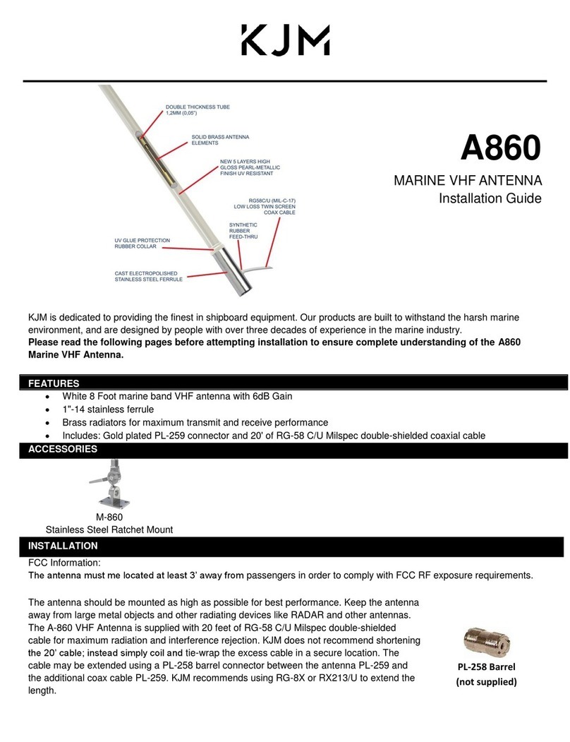
KJM A860 User manual

KJM

KJM A860 User manual

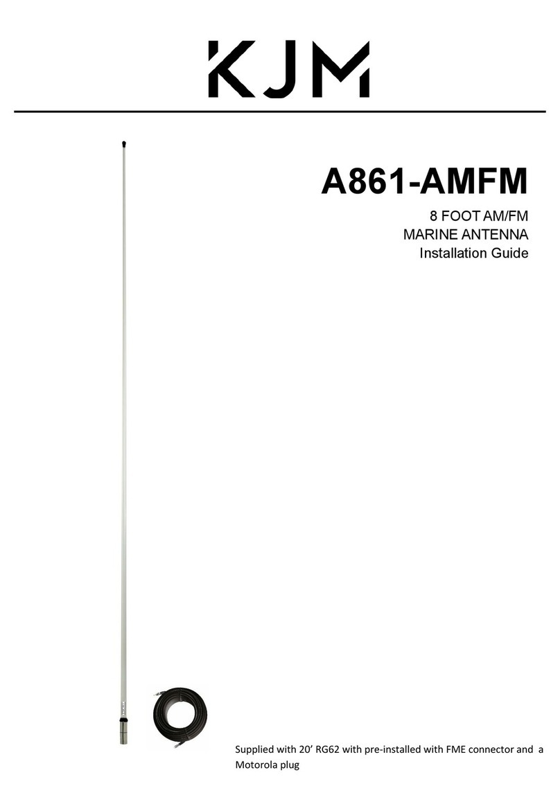
KJM A861-AMFM User manual

KJM

KJM A861-AMFM User manual

KJM A860-V User manual

KJM

KJM A860-V User manual

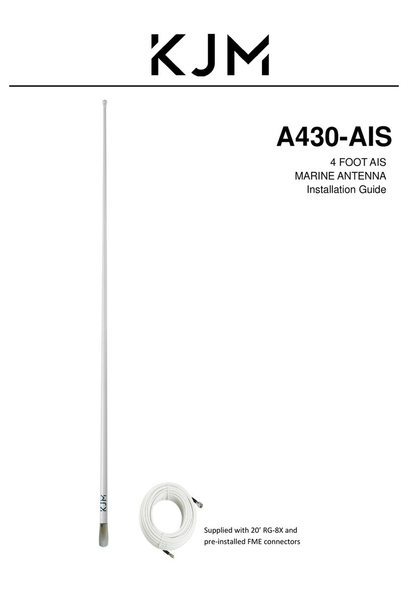
KJM A430-AIS User manual

KJM

KJM A430-AIS User manual

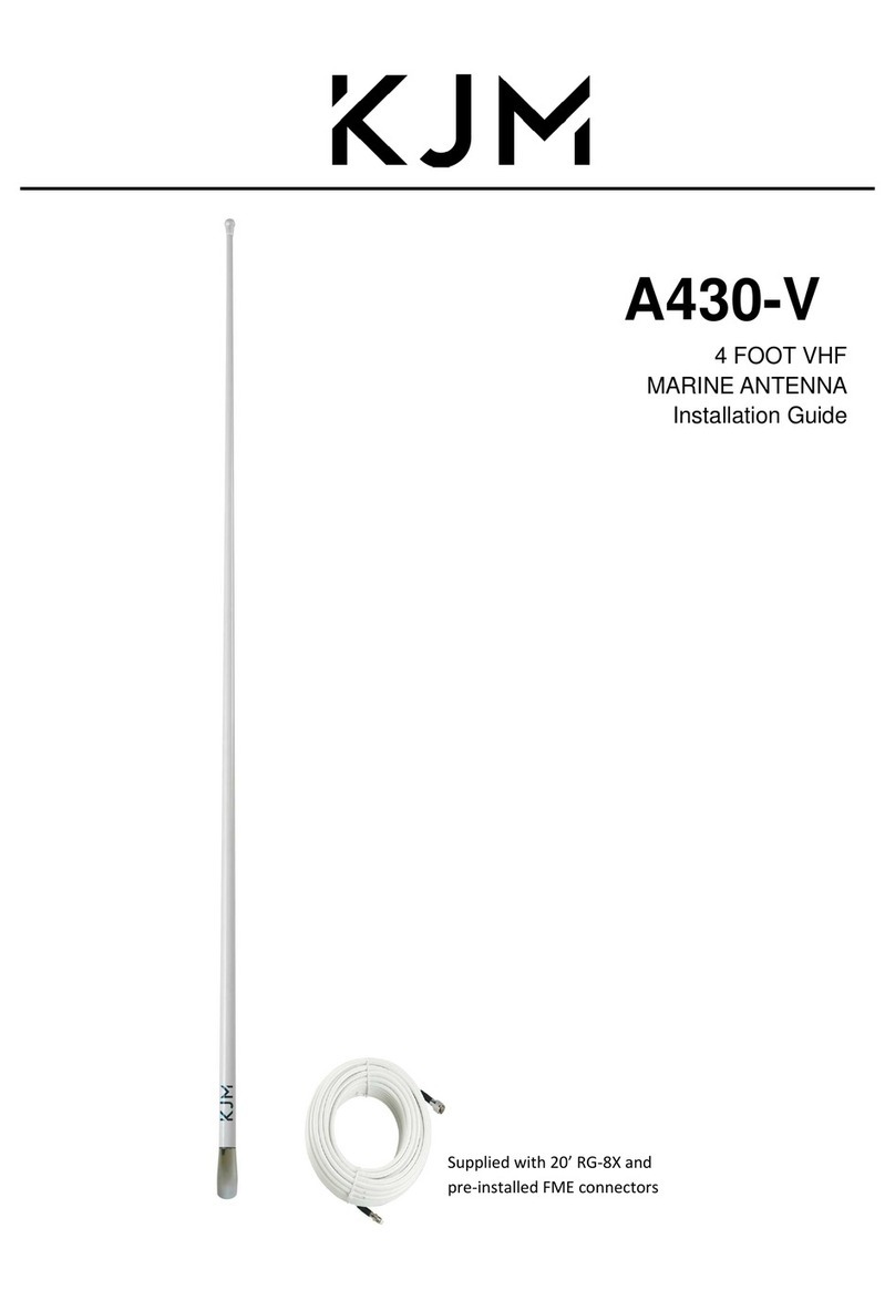
KJM A430-V User manual

KJM

KJM A430-V User manual

Popular Antenna manuals by other brands

Garmin A-33 installation manual

Garmin

Garmin A-33 installation manual

EPAK Premium Line TV61TV90 manual

EPAK

EPAK Premium Line TV61TV90 manual

DESHIBO GA-450 manual

DESHIBO

DESHIBO GA-450 manual

Matchmaster Digimatch 01MM-DC21A installation instructions

Matchmaster

Matchmaster Digimatch 01MM-DC21A installation instructions

Hama 00121663 operating instructions

Hama

Hama 00121663 operating instructions

SEDEA FLAG TV HD manual

SEDEA

SEDEA FLAG TV HD manual

Signal Kicker Antennas Base Kicker installation guide

Signal Kicker Antennas

Signal Kicker Antennas Base Kicker installation guide

Audix ANTDA4161 user guide

Audix

Audix ANTDA4161 user guide

Antenna Experts AP-240030 installation manual

Antenna Experts

Antenna Experts AP-240030 installation manual

Netkrom AIRNET 11Mb CPE BRIDGE installation guide

Netkrom

Netkrom AIRNET 11Mb CPE BRIDGE installation guide

Cisco FM TUBE Installation and configuration manual

Cisco

Cisco FM TUBE Installation and configuration manual

l-com HG2415Y installation instructions

l-com

l-com HG2415Y installation instructions

Wilson Electronics 301134 installation guide

Wilson Electronics

Wilson Electronics 301134 installation guide

Valcom AS-3772B/U Technical manual

Valcom

Valcom AS-3772B/U Technical manual

Emos EM-9086 quick start guide

Emos

Emos EM-9086 quick start guide

Laird AP-ANT-40 Assembly and installation instructions

Laird

Laird AP-ANT-40 Assembly and installation instructions

ETS-Lindgren 3110B manual

ETS-Lindgren

ETS-Lindgren 3110B manual

Printronix 182043 specification

Printronix

Printronix 182043 specification

manuals.online logo
manuals.online logoBrands
  • About & Mission
  • Contact us
  • Privacy Policy
  • Terms and Conditions

Copyright 2025 Manuals.Online. All Rights Reserved.