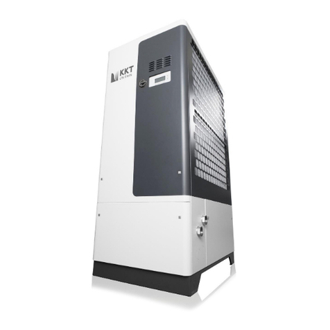
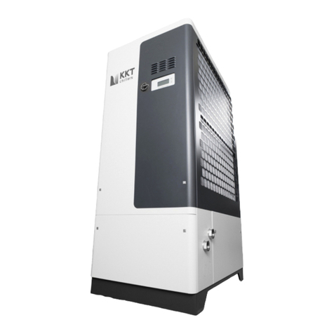
KKT KCC 215-L Series User manual

Installing Instruction
Chiller of the KCC Series
Revision Rev.07 Type KCC 215-L-... page 1
vom 21.09.2007
H:\Siemens MED\KCC 215 L\03_Dokumente\Installationsanleitung\INSTALLING INSTRUCTIONenglVers07.doc
INSTALLATION INSTRUCTIONS
KCC-SERIES CHILLER
TYPE KCC 215-L-…
Customer Siemens Medical Solutions
Allee am Röthelheimpark 2
91052 Erlangen
Manufacturer KKT KRAUS KLIMATECHNIK GMBH
Industriestraße 23 a
D-91207 Lauf / Germany
Phone +49-9123-1 74 01
Fax +49-9123-8 24 56
KKT-Kraus Servicehotline:
Toll Free from US (866) 517 6867

Installing Instruction
Chiller of the KCC Series
Revision Rev.07 Type KCC 215-L-... page 2
vom 21.09.2007
H:\Siemens MED\KCC 215 L\03_Dokumente\Installationsanleitung\INSTALLING INSTRUCTIONenglVers07.doc
Contents
I Technical Data ...................................................................................................... 4
I. Basics .................................................................................................................. 5
II. Installation site .................................................................................................... 7
a) Ambient temperatures .................................................................................... 7
b) Clearance....................................................................................................... 7
c) Servicing and repair access............................................................................ 7
d) Air flow............................................................................................................ 7
e) Load capacity of the base............................................................................... 7
III. Transport route/transport ................................................................................. 10
a) Transport measurements ............................................................................. 10
b) Transport weight........................................................................................... 10
c) Transport safety locks .................................................................................. 10
d) Crane transport ............................................................................................ 10
e) Dimensions in inch ....................................................................................... 12
f) Dimensions in mm......................................................................................... 13
g) Weights ........................................................................................................ 14
IV. Power supply/electrical connection................................................................. 14
a) Follow local regulations ................................................................................ 14
b) Voltage, frequency, tolerances ..................................................................... 14
c) Type of cable ................................................................................................ 14
d) Length and cable width ................................................................................ 14
e) Strain relief ................................................................................................... 14
f) Clamps .......................................................................................................... 15
g) Fuse ............................................................................................................. 16
h) Phase sequence........................................................................................... 16
i) EMC Compatibility and Grounding ................................................................ 17
j) Data cable ..................................................................................................... 18
V. Interface filter panel (IFP) ................................................................................. 21
Scope of IFP supply: ........................................................................................ 21
Installation of IFP.............................................................................................. 21
VI. Water connection............................................................................................. 22
a) Pipe material ................................................................................................ 22
b) Relation of pipe diameter to distance between chiller and IFP..................... 22
c) Dimensions of the connections..................................................................... 22
d) Inflow and outflow......................................................................................... 22
e) Water quality ................................................................................................ 22
f) Glycol ............................................................................................................ 23
g) Filling............................................................................................................ 23
h) Vents and air chambers ............................................................................... 23
VII. Initial start-up .................................................................................................. 26
VIII. SPS Settings ................................................................................................ 27
IX. Control ............................................................................................................. 29
Installing Instruction
Chiller of the KCC Series
Revision Rev.07 Type KCC 215-L-... page 3
vom 21.09.2007
H:\Siemens MED\KCC 215 L\03_Dokumente\Installationsanleitung\INSTALLING INSTRUCTIONenglVers07.doc
a) Pump............................................................................................................ 29
b) Water pressures ........................................................................................... 29
c) Compressor .................................................................................................. 29
d) Vents ............................................................................................................ 29
e) Refrigerant pressures................................................................................... 29
f) Temperatures ................................................................................................ 29
X Overview water chiller and IFP .......................................................................... 30
XI Trouble Shooting .............................................................................................. 31
XII. Maintenance .................................................................................................. 36
XIII. Warranty ....................................................................................................... 36
XIV. Safety Warnings........................................................................................... 36

Installing Instruction
Chiller of the KCC Series
Revision Rev.07 Type KCC 215-L-... page 4
vom 21.09.2007
H:\Siemens MED\KCC 215 L\03_Dokumente\Installationsanleitung\INSTALLING INSTRUCTIONenglVers07.doc
I Technical Data
Model Outdoor
Dimensions Depth 940 mm
Width 3040 mm
Height 1850 mm
Weight without refrigerant load ca. 1066 kg
Weight with load ca. 1090 kg
Shipping weight ca. 1600 kg
Weight total refrigerant load 24.0 kg
Quantity of air 2x 18000 m³/h
Number of fans 4
Refrigerant R134a
Required quantity of refrigerant 2x12kg
High-pressure switch 19 bar
Water connection inlet internal 2“ G" female thread
Water connection outlet internal 2“ G" femalethread
Cold water temperature outlet min. 19-22 °C ±0.5 K
Cold water temperature inlet max. 30 °C
Primary water pump type 60Hz IN-V 10-50(60Hz)
Primary water pump type 50Hz IN-V 10-70(50Hz)
Rated water capacity min. 7.8 m³/h
Rated water pressure 6.5 bar
Ambient temperature min.-20 °C
max.+48 °C
Cooling capacity 60.0 kW
Rated cold water outlet temperature 20 °C
Temperature of surroundings 48 °C
Main supply 380-480 V / 3Ph / 50-60 Hz
Control voltage 24 VDc
Fluctuations in main voltage max. -14+10 %
Fluctuations in frequency max. ±1 Hz
Power input max. 29 kW
Noise level at 5 m max.68 db(A)
at max cooling capacity and max. ambient temperature

Installing Instruction
Chiller of the KCC Series
Revision Rev.07 Type KCC 215-L-... page 5
vom 21.09.2007
H:\Siemens MED\KCC 215 L\03_Dokumente\Installationsanleitung\INSTALLING INSTRUCTIONenglVers07.doc
I. Basics
Scope of Chiller supply:
•KCC215-L-…
•Installing Instruction inside the switch cabinet
•Manual inside the switch cabinet
•Data transfere cable 50m (164feet) in a box near the pump
•Short data transfere cable in a box near the pump
•Grounding in a box near the pump
•Overvoltage protection in a box near the pump
•Spare parts in a box near the pump
•Brass fittings for the connection Chiller inlet/outlet and piping (on the pump)
•Stainless steel fittings for the connetion piping and IFP (on the pump)
Carefully read the operating instructions located in the control cabinet before
beginning installation.
Check the equipment for damage on arrival and report any defects immediately.
Claims submitted later cannot be honored.
Please observe the following notes and warnings.
1. Removing the operating instructions from the cooling block voids the warranty!
2. The volume of the water circulation system of the cooling block ist approx. 17
liters (~4.5 gal) Please consider this by filling the water system with water
ethyleneglycol mixture.
3. Always operate the water circulation system at a volume of 35-38% ethylene
glycol.
This is regardless of the ambient temperature.
Non-compliance voids the warranty.
Use of automobile anti-freeze and propylene glycol is prohibited.
4. With the pump turned off, fill the system to a static water pressure of 1.5 bar
(21.75 psi) by Avanto an Chiller at the same level. (Also see Table 1 page24)
5. The cooling block operates completely independently of the MR system.
6. Voltage is still present in the KCC control cabinet when the MR system is
turned off. Risk of death!

Installing Instruction
Chiller of the KCC Series
Revision Rev.07 Type KCC 215-L-... page 6
vom 21.09.2007
H:\Siemens MED\KCC 215 L\03_Dokumente\Installationsanleitung\INSTALLING INSTRUCTIONenglVers07.doc
7. Even with the cooling block turned off, high surface temperatures can cause
burns. Risk of death!
Only trained and qualified personnel are permitted to install, start up, and repair the
cooling block.

Installing Instruction
Chiller of the KCC Series
Revision Rev.07 Type KCC 215-L-... page 7
vom 21.09.2007
H:\Siemens MED\KCC 215 L\03_Dokumente\Installationsanleitung\INSTALLING INSTRUCTIONenglVers07.doc
II. Installation site
a) Ambient temperatures
The chiller is designed to operate at ambient temperatures between –20°C (-4°F)
minimum and +48°C (+118.4°F) maximum.
Malfunctions can occur outside these specifications.
If the chiller is used at high ambient temperatures (higher than 40°C = 104°F)
the the chiller should be installed that the switch cabinet is not fully exposed
to the sun radiation when the maximum ambient temperature is prevent. If
this is not possible please install a sun protection!!
Support from KKT-Kraus could be requested.
b) Clearance
Maintain at least 100 cm (39.4 in.) around all four sides of the chiller for air intake
and servicing/repair.
Under no circumstances install a roof above the chiller.
c) Servicing and repair access
See Clearance
d) Air flow
Never obstruct the air intake to the condensers on the upper third of the chiller.
The diameter of the tubes may not be smaller than the size specified.
e) Load capacity of the base
Verify that the installation surface has sufficient load capacity.
A concrete foundation or sectional steel construction is recommended.
A concrete foundation needs to be 200 mm (7.8 in.) wider and 200 mm (7.8 in.)
longer than the cooling block. Final dimensions: approx. 3,200 mm (10.5 feet) long
by 1,100 mm (3.6 ft) wide.
The operating weight of the chiller is approx. 1,100 kg (2,425 lbs.).
It is important that the cooling block be installed on a level surface.

Installing Instruction
Chiller of the KCC Series
Revision Rev.07 Type KCC 215-L-... page 8
vom 21.09.2007
H:\Siemens MED\KCC 215 L\03_Dokumente\Installationsanleitung\INSTALLING INSTRUCTIONenglVers07.doc

Installing Instruction
Chiller of the KCC Series
Revision Rev.07 Type KCC 215-L-... page 9
vom 21.09.2007
H:\Siemens MED\KCC 215 L\03_Dokumente\Installationsanleitung\INSTALLING INSTRUCTIONenglVers07.doc

Installing Instruction
Chiller of the KCC Series
Revision Rev.07 Type KCC 215-L-... page 10
vom 21.09.2007
H:\Siemens MED\KCC 215 L\03_Dokumente\Installationsanleitung\INSTALLING INSTRUCTIONenglVers07.doc
III. Transport route/transport
a) Transport measurements
Length: approx. 3,200 mm (126 inches)
Width: approx. 1,100mm (43.3 inches)
Height: approx. 2,150mm (approx. 84.65 inches)
You also need to add the height of the transport equipment, such as pallets, lift
truck, transport rollers, etc.
b) Transport weight
Weight: approx. 1,600 kg (approx. 3,528 lbs.)
c) Transport safety locks
There are no transport safety locks to remove.
d) Crane transport
If a crane will be used to transport the chiller, note the following:
Lift the chiller only from its base. Insert two steel rods through the holes in the base.
The rods must be specifically designed for this purpose and able to support the
weight (1,100 kg./2,425 lbs.).
Secure the rods with locking pins to prevent shifting.
Use only straps or rope for lifting from the rods.
The straps or ropes must be held in place with a frame to keep them from pressing
into the side walls, gutters, and condenser body. (Refer to the following graphic).

Installing Instruction
Chiller of the KCC Series
Revision Rev.07 Type KCC 215-L-... page 11
vom 21.09.2007
H:\Siemens MED\KCC 215 L\03_Dokumente\Installationsanleitung\INSTALLING INSTRUCTIONenglVers07.doc

Installing Instruction
Chiller of the KCC Series
Revision Rev.07 Type KCC 215-L-... page 12
vom 21.09.2007
H:\Siemens MED\KCC 215 L\03_Dokumente\Installationsanleitung\INSTALLING INSTRUCTIONenglVers07.doc
e) Dimensions in inch

Installing Instruction
Chiller of the KCC Series
Revision Rev.07 Type KCC 215-L-... page 13
vom 21.09.2007
H:\Siemens MED\KCC 215 L\03_Dokumente\Installationsanleitung\INSTALLING INSTRUCTIONenglVers07.doc
f) Dimensions in mm

Installing Instruction
Chiller of the KCC Series
Revision Rev.07 Type KCC 215-L-... page 14
vom 21.09.2007
H:\Siemens MED\KCC 215 L\03_Dokumente\Installationsanleitung\INSTALLING INSTRUCTIONenglVers07.doc
g) Weights
Net weight: 1,060 kg. (2,337 lbs.)
Operating weight: approx. 1,100 kg. (2,425 lbs.)
Transport weight: approx. 1,600 kg (3,527.4 lbs.)
Refrigerant: approx. 2 X 12 kg. (26.45 lbs.) R 134a
IV. Power supply/electrical connection
a) Follow local regulations
Strictly adhere to the regulations of the local power company and authorities. Only
trained, authorized persons are permitted to connect the power.
b) Voltage, frequency, tolerances
Voltage range: 380 - 480 Volt –14%+10%
Frequency range: 50 – 60Hz +/-1Hz
c) Type of cable
Make sure to use appropriately designed and approved cables when routing.
d) Length and cable width
A cable width of at least 16mm² per phase is required for cables up to 50 meters
(164 ft.) in length.
Therefore, a 5 x 16mm² cable is required.
e) Strain relief
The input cable must be fitted on both sides with a strain relief.

Installing Instruction
Chiller of the KCC Series
Revision Rev.07 Type KCC 215-L-... page 15
vom 21.09.2007
H:\Siemens MED\KCC 215 L\03_Dokumente\Installationsanleitung\INSTALLING INSTRUCTIONenglVers07.doc
f) Clamps
Insert the input cable through the cable feed-through (see photograph) next to the
water connections. Route it into the control cabinet through the cable channel
installed on the back of the control cabinet.
Use the clamps to secure the routed cable (see photograph).
Attention!!
Do not pass the power supply line across the switch cabinet!!
Use cable opening in the lower right hand side of cabinet!!
Drilling holes into and running cables into the cabinet can cause interferences with
the regulation electronics!!

Installing Instruction
Chiller of the KCC Series
Revision Rev.07 Type KCC 215-L-... page 16
vom 21.09.2007
H:\Siemens MED\KCC 215 L\03_Dokumente\Installationsanleitung\INSTALLING INSTRUCTIONenglVers07.doc
g) Fuse
Maximum 63 A slow-blowing fuse for pre-fusing.
Maximum overcurrent of 200 A for 50 msec.
h) Phase sequence
Observe the correct phase sequence when routing the wires, otherwise the cooling
block will not start. A phase sequence relay (5A1) is installed for this purpose (see
photograph).
The top LED is lit when operating voltage is present.
The LED underneath lights during overvoltage.
The next lower LED lights during undervoltage.
The fourth LED from the top lights during asymmetry, incorrect phase sequence,
and power outage.
The bottom LED lights when the output relay is activated.

Installing Instruction
Chiller of the KCC Series
Revision Rev.07 Type KCC 215-L-... page 17
vom 21.09.2007
H:\Siemens MED\KCC 215 L\03_Dokumente\Installationsanleitung\INSTALLING INSTRUCTIONenglVers07.doc
i) EMC Compatibility and Grounding
This comments are compiled to help the field electrician to install the grounding of the
power supply and to get a EMC Compatibility.
All electrical equipment produces radio and line-borne interference at various
frequencies. The cables pass this on to the environment like an aerial.
The basic countermeasures are isolation of the wiring of control and power
components, proper grounding and shielding of cables.
A large contact area is necessary for low-impedance grounding of HF interference.
The use of grounding straps instead of cables is therefore definitely advisable.
Moreover, cable shields must be
connected with purpose-made ground
clips.
The grounding surface must be highly
conductive bare metal. Remove any
coats of varnish and paint.
The width of the grounding wire must be min. 16mm² (AWG 6) or of the same width
of the power supply.
The grounding must be an isolated ground and must connected on the ground
terminal (X1) in the switch cabinet. The ground resistance must be less than 10 Ohm.
Metal cable conduits are not allowed for grounding.
The piping of the chiller (supply and return) have to be grounded too.
Do not share the ground wire with other devices.
Always use a ground wire that complies with technical standards on electrical
equipment and minimize the length of the ground wire.
When using more than one Inverter, be careful not to loop the ground wire.
(e.g. a CT-Chiller KPC108-L-U/S stands near an Avanto-Chiller KCC215-L-U/S)

Installing Instruction
Chiller of the KCC Series
Revision Rev.07 Type KCC 215-L-... page 18
vom 21.09.2007
H:\Siemens MED\KCC 215 L\03_Dokumente\Installationsanleitung\INSTALLING INSTRUCTIONenglVers07.doc
j) Data cable
Attach the “X8 Chiller” end of the 16-pin data cable (included) to the green
connector (see photograph) at the top right of the control cabinet.
Power plug
A separate feed-through for the power plug is located on the right wall of the control
cabinet (see photograph).

Installing Instruction
Chiller of the KCC Series
Revision Rev.07 Type KCC 215-L-... page 19
vom 21.09.2007
H:\Siemens MED\KCC 215 L\03_Dokumente\Installationsanleitung\INSTALLING INSTRUCTIONenglVers07.doc
Feed-through
•Run the cable from the chiller to the MR electronic cabinets.
•Connect the lightning arrester with the 164 ft / 50 m data cable.
•Connect the short data cable with the lightning arrester.
•Attach the other end of the short data cable on the electronics cabinet ACC
X81 of the MR system.
•Connect the grounding wire.

Installing Instruction
Chiller of the KCC Series
Revision Rev.07 Type KCC 215-L-... page 20
vom 21.09.2007
H:\Siemens MED\KCC 215 L\03_Dokumente\Installationsanleitung\INSTALLING INSTRUCTIONenglVers07.doc
Table of contents
Other KKT Chiller manuals
Popular Chiller manuals by other brands

Daikin
Daikin WCT Series operating & maintenance manual

Beko
Beko BEKOBLIZZ LC 480 Instructions for installation and operation

Trane
Trane CVHE Installation, operation and maintenance

Carrier
Carrier 30MP Installation and startup guide

Heidolph
Heidolph RotaChill Large manual

Conair
Conair EP2 series user guide

MCED systems
MCED systems BEF-02 Service manual

York
York MILLENNIUM YK Wiring diagram

MTA
MTA TAEevo Tech MINI Operating and maintenance manual

Carrier
Carrier AQUASNAP 30RAP010-150 Controls, start-up, operation, service, and troubleshooting

Cleveland
Cleveland TCCT-60-CC supplementary guide

York
York YCAS0250 Wiring diagram