KKT KPC 108-L-U/S User manual

83003702.K Operating Instruction
Type KPC 108-L-U/S
page 1
\\FILER02\ALLGEMEIN\02 - TECHNISCHE UNTERLAGEN KKT\ORIGINALE\830XXX BEDIENUNGSANLEITUNGEN\KPC\83003702.K KPC108- L-US.DOC
Manufacturer
ait-deutschland GmbH
Industriestraße 3
95359 Kasendorf
Germany
T +49 9228 9977 0
F +49 9228 9977 149
W www.kkt-chillers.com
Representative in the US and Service Center
KKT chillers, Inc.
1280 Landmeier Road
Elk Grove Village
IL 60007
T +1 847 734 1600
F +1 847 734 1601
TF +1 866 517 6867
YOUR LOCAL SERVICE CONTRACTOR IS:
COMPANY NAME:
PHONE NUMBER: FAX NUMBER:

83003702.K Operating Instruction
Type KPC 108-L-U/S
page 2
\\FILER02\ALLGEMEIN\02 - TECHNISCHE UNTERLAGEN KKT\ORIGINALE\830XXX BEDIENUNGSANLEITUNGEN\KPC\83003702.K KPC108- L-US.DOC
Contents
1General Remarks ...................................................................................................................................................4
1.1 Warranty .................................................................................................................................................5
1.2 Safety Warnings ......................................................................................................................................5
2General Description ...............................................................................................................................................6
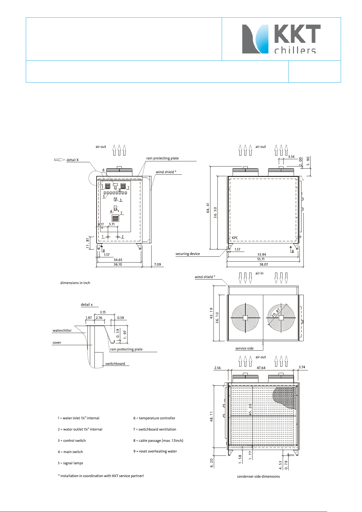
2.1 Drawings ...............................................................................................................................................10
2.1.1 KPC 108-L-U/S Outdoor Model ....................................................................................................................10
3Brief operating instructions..................................................................................................................................11
3.1 Installing, maintenance and repair .........................................................................................................11
3.2 Linking to power supply .........................................................................................................................11
3.3 Filling the unit with cooling medium .......................................................................................................11
3.4 EMC Compatibility and Grounding ..........................................................................................................11
3.5 Draining air from the unit .......................................................................................................................13
3.6 Switch settings of main chiller functions (exfactory settings)...................................................................13
4Technical Specifications ......................................................................................................................................15
4.1 Data sheet ............................................................................................................................................15
5Transport .............................................................................................................................................................16
6Installing the industrial cooler ..............................................................................................................................17
7Notes on the cooling medium connections...........................................................................................................21
8Power supply .......................................................................................................................................................24
9Operating instructions..........................................................................................................................................25
9.1 Switching ON the Industrial Cooler .........................................................................................................25
9.2 High/low pressure control......................................................................................................................25
9.3 Electronic controls .................................................................................................................................26
9.4 Regulating refrigerating capacity ............................................................................................................26
9.5 Condenser pressure regulation ..............................................................................................................26
9.6 Safety functions to protect components of cooling water circuit..............................................................26
9.7 Collective alarm.....................................................................................................................................26
9.8 Flow switch............................................................................................................................................26
9.9 Dirt trap.................................................................................................................................................26
10 Preventiv Maintenance ........................................................................................................................................27
11 TROUBLE SHOOTING ............................................................................................................................................29
12 Description of the individual parts .......................................................................................................................31
12.1 Compressor...........................................................................................................................................31
12.2 Condenser.............................................................................................................................................59
12.2.1 Built-in Condenser.......................................................................................................................................60
12.3 Fans......................................................................................................................................................61
12.4 Evaporator.............................................................................................................................................67
12.5 Electronic temperature controller ...........................................................................................................67
12.6 Frequency Inverter.................................................................................................................................73
12.7 Pressure limiter .....................................................................................................................................78
12.7.1 Low pressure switch....................................................................................................................................78
12.7.2 High pressure switch...................................................................................................................................78
12.8 Pressure Transmitter .............................................................................................................................81
12.9 Sight glass.............................................................................................................................................85

83003702.K Operating Instruction
Type KPC 108-L-U/S
page 3
\\FILER02\ALLGEMEIN\02 - TECHNISCHE UNTERLAGEN KKT\ORIGINALE\830XXX BEDIENUNGSANLEITUNGEN\KPC\83003702.K KPC108- L-US.DOC
12.10 Filter drier..............................................................................................................................................86
12.11 Thermo-Expansion valve ........................................................................................................................87
12.12 Drier + Core...........................................................................................................................................88
12.13 Liquid receiver.......................................................................................................................................89
12.14 Water pump ..........................................................................................................................................90
12.15 Flow switch (Type KPC 108-L-U/S)........................................................................................................101
12.16 Water heater (Type KPC 108-L-U/S) .....................................................................................................106
12.17 Air vent................................................................................................................................................108
12.18 Membrane safety valve........................................................................................................................109
12.19 Expansion vessel .................................................................................................................................110
12.20 Flow control valve ................................................................................................................................111
12.21 Dirt trap...............................................................................................................................................112
12.22 Manometers........................................................................................................................................112
13 Switch gear ........................................................................................................................................................113
13.1 Remote control panel ..........................................................................................................................113
13.1.1 Collective alarm ........................................................................................................................................113
14 Safety notes.......................................................................................................................................................113
14.1 Notes for refrigerant ..............................................................................................................................113
14.1 Instructions regarding machine oil .......................................................................................................114
15 Wiring diagram...................................................................................................................................................115

83003702.K Operating Instruction
Type KPC 108-L-U/S
page 4
\\FILER02\ALLGEMEIN\02 - TECHNISCHE UNTERLAGEN KKT\ORIGINALE\830XXX BEDIENUNGSANLEITUNGEN\KPC\83003702.K KPC108- L-US.DOC
1General Remarks
Industrial coolers Type KPC 108-L-U/S,
Manufacturer: ait-deutschland GmbH
Industriestraße 3
95359 Kasendorf
Germany
T +49 9228 9977 0
F +49 9228 9977 149
E info@kkt-chillers.com
W www.kkt-chillers.com
After-sales: ait-deutschland GmbH
Industriestraße 3
95359 Kasendorf
Germany
T +49 9228 9977 7190
F +49 9228 9977 7474
W www.kkt-chillers.com
Refrigerant R134a
Total filling weight 7,0 kg outdoor model
Permitted working pressure: 19 bar
Cooling medium 62/38 % water/glycol mixture outdoor model
CAUTION! Ethylene glycol must be added at the rate of 38 % of the cooling medium volume anytime –
otherwise warranty void!
Do not use automotive antifreeze.
Never install automatic water refill system.
After the connect the refrigerant circuit –check the valve of the low pressure manometer.
IN CASES OF EMERGENCY TURN OFF THE AGGREGATE BY THE MASTER SWITCH !

83003702.K Operating Instruction
Type KPC 108-L-U/S
page 5
\\FILER02\ALLGEMEIN\02 - TECHNISCHE UNTERLAGEN KKT\ORIGINALE\830XXX BEDIENUNGSANLEITUNGEN\KPC\83003702.K KPC108- L-US.DOC
1.1 Warranty
The unit is supplied finished, tested and ready to work. The unit warranty will be void if any modification to the
unit is carried out without written agreement of KKT.
For warranty purposes, the following conditions must be satisfied:
The initial start of the unit must be carried out by trained personnel from an Authorized KKT Service Partner.
Maintenance must be carried out at least twice a year by properly trained personnel.
Only genuine KKT spare parts must be used.
For KPC108-L-U/S: Ethylene glycol must be added to the rate of 38Vol%.
The manual (this document) must not remove from the chiller.
All the scheduled maintenance operations detailed in this manual must be performed at the specified
times. Please use a higher amount of services if the local conditions require it.
The “Warranty Registration” has to be send return to KKT chillers
Failure to satisfy any of these conditions will automatically void the
warranty.
1.2 Safety Warnings
-Cooling water circuit is pressurized.
Switch off the chiller and depressurize before servicing the cooling water circuit.
-Drain water from pipes and spare parts before shipment.
-Nominal static filling pressure when Chiller has been switched off: 1,5bar. The pressure of the expansion tank is
without counter pressure from the “water / glycol – side” = 1,0 bar.
-Don`t handle valves while the Chiller is running
-Ethylene glycol must be added at the rate of 38% of the volume of water anytime otherwise warranty void.
-The rate depends not on the local ambient temperature.
-Don’t use automotive antifreeze.
-Voltage continuous to be present at the terminals, even after the medical device has been switched off.
-Parts in the refrigerant circuit are hot, even the Chiller has been switched off.
Warranty void if manual removed from chiller.
OBSERVE THE SAFETY RULES
Before commencing work on the unit, switch the plant to voltage-free
IN CASES OF EMERGENCY TURN OFF THE AGGREGATE BY THE MASTER SWITCH !
Caution! Work on electric and refrigerant circuits should only be performed by qualified operatives
Observe the safety rules!
Wear safety gloves and glasses when working on unit to avoid injury.
Wear long sleeve shirt and pants when working on unit.
No loose clothing items allowed to avoid injury.
Please read the manual.

83003702.K Operating Instruction
Type KPC 108-L-U/S
page 6
\\FILER02\ALLGEMEIN\02 - TECHNISCHE UNTERLAGEN KKT\ORIGINALE\830XXX BEDIENUNGSANLEITUNGEN\KPC\83003702.K KPC108- L-US.DOC
2General Description
The industrial coolers of the KPC series are fully assembled, factory inspected and tested, and suitable for fully-
automatic operation.
The industrial cooler of the KPC series consists of the refrigerant circuit, the cooling medium circulation, the transfer
station, the switch box and the remote control panel.
The refrigerant circuit includes compressor, primary side of the heat exchanger, air cooled condenser, necessary
equipment for liquid and gaseous refrigerant, safety and control device.
The cooling medium circulation includes secondary side of the heat exchanger with automatic air vent, medium heating
(electrical), circulation pump, expansion receiver, pressure relief valve, necessary equipment for cooling medium,
safety and control device.
The transfer station includes supply and return connections with shut-off valves, necessary equipment for cooling
medium, filling and draining cocks.
The refrigerant circuit and the cooling medium circulation are designed as a cooling block with built in switch box
Cooling block Type KPC 108 - L - U/S 60 Hz
air-cooled design for outdoor use
The control elements are integrated in the front of the switch box. The remote control panel includes control switch,
lamp “run” as a status massage and lamp “fault” as a general fault massage.
The temperature set on the controller is kept automatically.
The cooling medium is constantly circulated by the pump.
The process heat is being transmitted from the cooling medium to the heat exchanger (evaporator of the refrigerant
circuit) and used for refrigerant evaporating (cooling). The compressor raises the gaseous refrigerant to a higher
pressure so that the warmth can be released via the condenser to the surrounding air. Consequently good air supply
and escape are vital for the proper running of the plant.
The cooling medium supply temperature can be changed from +7 °C to +12 °C by the temperature controller in front
of switch box.
Attention! Changes in the settings should only be made by qualified operatives.
The housing with stable welded, galvanized framework-construction, lateral cover-plates with drawer-edges made of
galvanized steel plate with ventilating nozzles worked into the top plate.
Framework-construction and top-plates are powder-coated on the inside and outside. All outer fastening screws rust-
proof, inspection-caps at the front easily removable for maintenance using casement-fastener caps.
Compressor, refrigerant and cooling medium mountings, additionally sound and rain-proofed using a galvanized cover-
plate.
Condenser axial-fans, pressure switch controlled condenser pressure dependent. Ventilators equipped with protective-
grating on the delivery side of the pump.
Laterally mounted condenser heat exchanger made of copper-aluminum with covering galvanized framework,
enameled fully in black.

83003702.K Operating Instruction
Type KPC 108-L-U/S
page 7
\\FILER02\ALLGEMEIN\02 - TECHNISCHE UNTERLAGEN KKT\ORIGINALE\830XXX BEDIENUNGSANLEITUNGEN\KPC\83003702.K KPC108- L-US.DOC
Compressor-unit, consisting of:
Stable base-frame construction made of steel-profiles, powder-coated. Vibration-absorbing-mounted fully hermetic
SCROLL compressor with motor and suction-gas cooling. Complete special shut-off valves placed at the pressure and
suction side. Refrigerant power-inputs of flexible design. Refrigerant circuit with collector, filter-dryer, inspection glass
and moisture indicator, solenoid valve, service-valves as well as the complete internal copper-pipe work with refrigerant
and special oil filling.
Thermostatic expansion-valve and plumb high-capacity copper-brazed plate heat exchanger –evaporator. The plates
with optimized profile for efficiency heat transfer.
Evaporator and suction-side pipe work with diffusion-seal insulation.
Safety pack, consisting of:
Crankcase heater, high / low pressure switches as well as protective motor relay.
Shut-off ball valve at the cooling medium entry, dirt absorber, expansion tank, feeder and safety valves. High-pressure
centrifugal-pump adjusted to the overall system, filling and drainage valves with piping terminal, automatic air vent,
manometers and machine-thermometers in forward and return flow. Quantity balancing-valve, connection piece for
computer terminal in cooling medium supply.
Temperature control as hot gas by-pass control with solenoid valve.
Electronic digital temperature controller with control range limitation for set point and actually temperature.
Condenser fan control via pressure transmitter in refrigerant circuit and frequency inverter.
The high pressure pressostat (pressure switch) for system safety.
Internal cooling medium copper-brazed piping with diffusion-seal insulation.
All necessary block and clip angles used for refrigerant und cooling medium construction are made of rust-proof and
powder-coated material.
Switch-box with front door integrated in cooling block, system of protection IP 54, wired according to VDE-regulations
with a main switch, supply-check indicator lamp, phase monitoring relay and Siemens components such as, overload
release, sliding-panel, motor safety-switch, control-switch and indicator lamps.
A pump post-relay for the safety of the vaporizer as well as pot. proof contacts for "supply-control" and "collective fault
messages". It is still possible to connect a remote board.
The switch box of the outdoor version contains a switch box heater and a switch box ventilator.

83003702.K Operating Instruction
Type KPC 108-L-U/S
page 8
\\FILER02\ALLGEMEIN\02 - TECHNISCHE UNTERLAGEN KKT\ORIGINALE\830XXX BEDIENUNGSANLEITUNGEN\KPC\83003702.K KPC108- L-US.DOC
Overview of outdoor industrial cooler KPC Series

83003702.K Operating Instruction
Type KPC 108-L-U/S
page 9
\\FILER02\ALLGEMEIN\02 - TECHNISCHE UNTERLAGEN KKT\ORIGINALE\830XXX BEDIENUNGSANLEITUNGEN\KPC\83003702.K KPC108- L-US.DOC
KPC 108-L-U/S

83003702.K Operating Instruction
Type KPC 108-L-U/S
page 10
\\FILER02\ALLGEMEIN\02 - TECHNISCHE UNTERLAGEN KKT\ORIGINALE\830XXX BEDIENUNGSANLEITUNGEN\KPC\83003702.K KPC108- L-US.DOC
2.1 Drawings
2.1.1 KPC 108-L-U/S Outdoor Model

83003702.K Operating Instruction
Type KPC 108-L-U/S
page 11
\\FILER02\ALLGEMEIN\02 - TECHNISCHE UNTERLAGEN KKT\ORIGINALE\830XXX BEDIENUNGSANLEITUNGEN\KPC\83003702.K KPC108- L-US.DOC
3Brief operating instructions
3.1 Installing, maintenance and repair
Only qualified operatives with the requisite knowledge, equipment and facilities should maintenance and repair the
industrial cooler.
If its necessary to change the filling weight of the refrigerant circuit, please note:
Fill only with the refrigerants listed on the manufacturer name plate, and only up to the indicated filling weight.
OBSERVE THE SAFETY RULES
Before work on the industrial cooler, switch the plant to voltage-free and make sure against unauthorized switching
ON.
3.2 Linking to power supply
The size of the connection cable had to be conform to the local regulations. For current values and power input see
Switch Gear.
The industrial coolers of the KPC series are generally designed for a main supply of 480V 3Ph 60 Hz.
The connection L1, L2, L3, PE is performed via the terminal block in the switch box.
The cooling block is switched on via the master switch .
3.3 Filling the unit with cooling medium
The cooling circulation will be filled with cooling medium (mixture of 62 % clean water –drinking water quality –and
38 % glycol).
Open front panel and fill to a pressure of 1,5 bar via the feed cock.
After filling, check all connections for leakage.
3.4 EMC Compatibility and Grounding
This comments are compiled to help the field electrician to install the grounding of the power supply and to get a EMC
Compatibility.
All electrical equipment produces radio and line-borne interference at various frequencies. The cables pass this on to
the environment like an aerial.
The basic countermeasures are isolation of the wiring of control and power components, proper grounding and
shielding of cables.
A large contact area is necessary for low-impedance grounding of HF interference. The use of grounding straps
instead of cables is therefore definitely advisable.
Moreover, cable shields must be
connected with purpose-made ground
clips.
The grounding surface must be highly
conductive bare metal. Remove any
coats of varnish and paint.
The width of the grounding wire must be min. 16mm² (AWG 6) or of the same width of the power supply.
The grounding must be an isolated ground and must connected on the ground terminal (X1) in the switch cabinet.
The ground resistance must be less than 10 Ohm.

83003702.K Operating Instruction
Type KPC 108-L-U/S
page 12
\\FILER02\ALLGEMEIN\02 - TECHNISCHE UNTERLAGEN KKT\ORIGINALE\830XXX BEDIENUNGSANLEITUNGEN\KPC\83003702.K KPC108- L-US.DOC
Metal cable conduits are not allowed for grounding.
The piping of the chiller (supply and return) have to be grounded too.
Do not share the ground wire with other devices.
Always use a ground wire that complies with technical standards on electrical equipment and minimize the length of
the ground wire.

83003702.K Operating Instruction
Type KPC 108-L-U/S
page 13
\\FILER02\ALLGEMEIN\02 - TECHNISCHE UNTERLAGEN KKT\ORIGINALE\830XXX BEDIENUNGSANLEITUNGEN\KPC\83003702.K KPC108- L-US.DOC
When using more than one Inverter, be careful not to loop the ground wire.
(e.g. a CT-Chiller KPC108-L-U/S stands near an Avanto-Chiller KCC215-L-U/S)
3.5 Draining air from the unit
The KPC 108 includes a cooling medium circulation.
In case air gets out of the system the cooling medium pressure drops down. If that happens you have to check the
cooling medium pressure and if its to low you have to refill the cooling medium circulation as shown in 3.3
The procedure should be repeated until no more air is in the cooling medium circulation.
After all these steps, turn both switches to position "1". If all the prerequisites for operation have been met, the
industrial cooler will start after 1 minute.
In case of malfunction: search for faults taken note of TROUBLE SHOOTING in this manual.
3.6 Switch settings of main chiller functions (exfactory settings)
remote control panel
main switch
control switch
"0"
"1"
"0"
"1"
"0"
"Auto"
"Hand"
standard
operation: pump
runs, compressor
and condenser fan
are running on
demand (water
temp. higher than
8°C), water heater
works on demand
(water temp. below
4°C),
overheating
protection: pump
switches of if water
temp. Is longer
than 30 minutes
higher than 30°C)
X
X
X
X
(or no
remote
control
connected
with chiller)
X
X

83003702.K Operating Instruction
Type KPC 108-L-U/S
page 14
\\FILER02\ALLGEMEIN\02 - TECHNISCHE UNTERLAGEN KKT\ORIGINALE\830XXX BEDIENUNGSANLEITUNGEN\KPC\83003702.K KPC108- L-US.DOC
stand by mode:
refrigerant circuit is
"switched off",
pump and heater
are running on
demand (water
temp. below 4°C),
X
(or no
remote
control
connected
with chiller)
X
X
X
X
X
X
X
switched off:
no function (switch
cabinet is not
under voltage)
position without effect
X
position without effect
remark: with the position "Auto" on the control switch is the remote control panel active.

83003702.K Operating Instruction
Type KPC 108-L-U/S
page 15
\\FILER02\ALLGEMEIN\02 - TECHNISCHE UNTERLAGEN KKT\ORIGINALE\830XXX BEDIENUNGSANLEITUNGEN\KPC\83003702.K KPC108- L-US.DOC
4Technical Specifications
4.1 Data sheet
Outdoor
Dimensions Depth 962 mm
Breadth 1,410 mm
Height 1,620 mm
Weight without refrigerant load 540 kg
Weight with refrigerant load 7.0 kg
Number of fans 2
Quantity of air 18,000
Refrigerant R134a
Required quantity of refrigerant 7 kg
Low-pressure switch see testreport
High-pressure switch 19 bar
Water connection inlet 1 1/4“ inside
Water connection outlet 1 1/4“ inside
Cold water temperature outlet min. 7 °C +/-0,5 K
Cold water temperature outlet max. 12 °C
Primary water pump type CR3-6
Rated water capacity max. 4.1 m³/h
Rated water pressure 3.0 bar
Ambient temperature min. -20 °C
max. +48 °C
Cooling capacity 15,0 kW
Rated cold water outlet temperature 11 °C
temperature of surroundings 40 °C
Exactitude of temperature ±0.5 K
Main supply 480 V/3Ph/60 Hz
Control voltage 24 V
Fluctuations in main voltage max. ±5 %
Fluctuations in output max. ±5 %
Power input max. 9 kW
Noise level at 5m 65 db(A) -

83003702.K Operating Instruction
Type KPC 108-L-U/S
page 16
\\FILER02\ALLGEMEIN\02 - TECHNISCHE UNTERLAGEN KKT\ORIGINALE\830XXX BEDIENUNGSANLEITUNGEN\KPC\83003702.K KPC108- L-US.DOC
5Transport
Transport on company premises may be done with a forklift truck. The appliance must however be kept in an upright
position and on no account tipped to the side. A visual inspection should be made on delivery to check for any damage.
Complaints should be made immediately to the haulage contractor and the insurance company must be notified at
once.
When transporting by crane,
please ensure that the housing is not subjected to pressure at the sides.
Place the lifting tubes in the holes in the feet at the base of the chiller. Lock the ends of the tubes in position with
locking pins and split pins as shown.
The capacity of the lifting gear must be adequate to lift the load in question. Check the weight of the unit, the capacity
of the lifting gear and ropes and there condition.
Check the suitability of the aforementioned equipment.

83003702.K Operating Instruction
Type KPC 108-L-U/S
page 17
\\FILER02\ALLGEMEIN\02 - TECHNISCHE UNTERLAGEN KKT\ORIGINALE\830XXX BEDIENUNGSANLEITUNGEN\KPC\83003702.K KPC108- L-US.DOC
6Installing the industrial cooler
The plant should be mounted in an upright position on a stable foundation.
(Weight with load: see technical specifications).
A distance of approx. 1 m should be kept free on all sides to allow sufficient access for operation and maintenance.
A space of 1,5 m must be left above the apparatus to ensure that air exhaust can leave freely by the outdoor model.
Further details can be found in the following installation plans.

83003702.K Operating Instruction
Type KPC 108-L-U/S
page 18
\\FILER02\ALLGEMEIN\02 - TECHNISCHE UNTERLAGEN KKT\ORIGINALE\830XXX BEDIENUNGSANLEITUNGEN\KPC\83003702.K KPC108- L-US.DOC
Type KPC 108-L-U/S Outdoor Unit
A distance of approx. 1 m should be kept free on all sides to allow sufficient access for operation and maintenance.
Picture is only to explain and not guilty for measurement.

83003702.K Operating Instruction
Type KPC 108-L-U/S
page 19
\\FILER02\ALLGEMEIN\02 - TECHNISCHE UNTERLAGEN KKT\ORIGINALE\830XXX BEDIENUNGSANLEITUNGEN\KPC\83003702.K KPC108- L-US.DOC

83003702.K Operating Instruction
Type KPC 108-L-U/S
page 20
\\FILER02\ALLGEMEIN\02 - TECHNISCHE UNTERLAGEN KKT\ORIGINALE\830XXX BEDIENUNGSANLEITUNGEN\KPC\83003702.K KPC108- L-US.DOC
Table of contents
Other KKT Chiller manuals
Popular Chiller manuals by other brands

CLIMAVENETA
CLIMAVENETA HRAN 0011 manual

Pfannenberg
Pfannenberg EB Series Installation, operation and maintenance manual

Host
Host HOST1210SH instruction manual

MTA
MTA MCCY-CY013 301 Operating and maintenance manual

Cornelius
Cornelius CH1500 Operator's & installation manual

Liebert
Liebert Process Fluid Chiller PS120A Specification sheet

Skope
Skope B600G-2 user manual

Enviroheat
Enviroheat OMNI OWC-5 Series Installation start-up maintenance

Yazaki
Yazaki AROACE installation instructions

Remco
Remco KWP Eco Series Operating and installation instructions

Daikin
Daikin EWWD120MBYNN Operation manual

Carrier
Carrier AQUAFORCE 30XA080-500 Controls, start-up, operation, service and troubleshooting instructions