KleenRite 32506 Product manual

®
32506
Upholstery and Drapery Cleaner
Operator and Parts Manual
Model No.:
32506 – 3 gal Extractor
KLEENRITE
1122 MAPLE STREET
MADERA CA 93637 U.S.A.
FAX: 1-559-673-5725 MNL32506
CUSTOMER SERVICE: 1-800-241-4865 Rev. 00 (08-98)

OPERATION
32506 (11-98)
This manual is furnished with each new model. It
provides necessary operation and mainte
nance
and the
re
r mail
e center,
f:
– per the
th manufacturer
supplied or equivalent parts.
MACHINE DATA
instructions and an illustrated parts list.
Read this manual completely and underst Please fill out at time of installation for future reference.
Model No.- _____________________________________
machine before operating or servicing it.
Use the illustrated Parts Lists to order parts. Befo
ordering parts or supplies, be sure to have your
machine model number and serial number handy.
Parts and supplies may be ordered by phone o
from any authorized parts and servic
Install. Date-____________________________________
Serial No.- _____________________________________
© Kleenrite Printed in U.S.A
distributor or directly from Kleenrite.
This machine will provide excellent service. However,
the best results will be obtained at minimum costs i
•The machine is operated with reasonable care.
•The machine is maintained regularly
maintenance instructions provided.
•The machine is maintained wi
.
Kleenrite Equipment is a registered United States trademark
TABLE OF CONTENTS
SAFETY PRECAUTIONS ................................. 3
MACHINE COMPONENTS............................... 4
MACHINE SETUP............................................. 4
MACHINE OPERATION WET-CLEANING ...... 5
MACHINE OPERATION-DRY CLEANING....... 6
MACHINE OPERATION-FLUSHING................ 6
DRAINING TANKS............................................ 7
FREEZE PROTECTION.................................... 7
MACHINE MAINTENANCE .............................. 7
TROUBLE SHOOTING..................................... 8
SPECIFICATIONS............................................. 9
PARTS LIST...................................................... 12
WARRANTY POLICY ....................................... 11
2

OPERATION
SAFETY PRECAUTIONS
This machine is intended for commercial use. It is
designed to wet clean or dry clean upholstery
drapery in an indoor environment and is not
constructed for any other use. Use only r
and
ecommended
rstand and practice the
roughout
this manual as indicated in their description:
cleaning solutions and accessory tools.
All operators must read, unde
following safety precautions.
The following safety alert symbols are used th
WARNING: To warn of hazards or unsafe
practices which could result in severe personal
ust be
lly dangerous
operator or equipment.
ly grounded.
.
– ll cord around sharp edges or
ling on cord.
e damage or faulty operation
dling instructions on
Do not mix water and OMS.
injury or death.
FOR SAFETY: To identify actions which m
followed for safe operation of equipment.
The following information signals potentia
conditions to the
FOR SAFETY:
.1 Do not operate machine:
– Unless trained and authorized.
– Unless operator manual is read and
understood. as.– In flammable or explosive are
– With damaged cord or plug.–If not in proper operating condition.
–Unless cord is proper
– In outdoor areas.
– In standing water. ion cord.– With the use of an extens
2. Before operating machine:
– Make sure all safety devices are in place
and operate properly
3. When using machine:
– Do not run machine over cord.
– Do not pull machine by plug or cord.
Do not pu
corners.
– Do not unplug by pul
– Do not stretch cord.
– Do not handle plugs with wet hands.
– Keep cord away from heated surfaces.
–Report machin
immediately.
–Follow mixing and han
chemical containers.
–
32506 (11-98) 3

4. Before leaving or servicing machine:
–Turn off machine. tlet.
WARNING: Do not use chlorinated solvents
or OMS with a flash point below 125° F. Do not use
OMS alone. Use a cleaning charger which raises
the flash point and enhances cleaning.
–Unplug cord from wall ou
5. When servicing machine:
–Unplug cord from wall outlet.
–oid moving parts. Do not wear loose
jackets, shirts, or sleeves.
Use manufacturer supplied or approve
replacement parts.
6. When dry cleaning:
–Always connect exhaust hose to vacuum
exhaust and vent to outside of building.
–Always use a high capacity air mover in
room being cleaned to dissipate vapors.
–Never heat in 208° F. heat range.
–Always secure both lids to tanks.
WARNING: Flammable materials or reactive
metals can cause an explosion or fire. Do not pick
up.
GROUNDING INSTRUCTIONS
Av
d–
Machine must be grounded. If it should
malfunction or breakdown, grounding provides a
path of for electrica
reduce the ectrical sh is
equipped with a cord having an equipment-
grounding connector and grounding plug. The
plug must be plugged into an appropriate outlet
that is properly installed in accordance with all
local codes and ordinances. Do not remove
ground pin; if missing, replace plug before use.
least resistance
risk of el l current to
ock. This machine
WARNING: Hazardous Voltage. Shock or
electrocution can result. Always unplug machine
before servicing.
GROUNDED OUTLET
(
3 HOLE
)
GROUNDING
PIN
32506 (11-98)
4

OPERATION
32506 (11-98) 5
MACHINE COMPONENTS
1. Recovery Tank
2. Solution Tank
3. Recovery Tank Lid
4. Solution Tank Lid
5. Power Cord
6. 208° F Heat Range Switch
7. Lid Latch
e Connector
8. Exhaust Hose Connector
9. Drain Valve
10. Vacuum Hos
11. Solution Hose Connector
12. Empty-Out Nozzle
13. Solution Line Purge Connector
MACHINE SETUP
2. Carefully check carton for signs of damage. y for use.
3.
4. ean bucket or hose, fill solution tank
Report damages at once to carrier. The machine is shipped fully assembled and is read
Connect hoses and tool to be used (Figure 1).
Using a cl
with 11 liters (3 gallons) of hot water, 60° C
(140° F) maximum (Figure 2).
WARNING: Do not use OMS cleaning
solutions with a flash point of less than 125° F.
5. Add a recommended cleaning chemical.
43
1
Fig. 1
Fig. 2
2
6
7
8
10
59
12
11
13

FOR SAFETY: When using machine, follow
mixing and handling instructions on chemical
containers.
32506 (11-98)32506 (11-98)
66

OPERATION
ATTENTION: If using po
32506 (11-98) 7
wdered cleaning
chemicals, mix prior to adding. xcellent
er cord into a grounded wall
use of an extension cord
7. Secure recovery tank place.
NOTE: If desired, water alone achieves e
cleaning results.
6. Plug machine’s pow
outlet (Figure 3).
FOR SAFETY: Do not operate machine unless
cord is properly grounded.
FOR SAFETY: Do not operate machine with the
.
lid in
MACHINE OPERATION– WET CLEANING
FOR SAFETY: Do not operate machine unless
operator manual is read and understood.
PRE-OPERATION AND HEATING
1. Vacuum carpet and remove other debris with
is is confirmed
the green 120° F solvent
4).
208° F, press the red
button until the green light goes out and the red
standard vacuum.
2. Inspect power cord for damage.
3. Turn on pump and be certain it has primed. When
it is primed, air bubbles and than solution can be
observed returning into the solution tank bottom.
4. Turn on heater switch. At this point the heater will
come on in the 120° F setting. Th
5. To increase temperature to
light comes on (Figure 5). Note: whenever the
heater is on the pump should be primed and
running. This will prevent small steam bubbles
from going backwards and cavitating a pump that
by the illumination of
activated light (Figure
had previously been primed.
CLEANING
1. Turn on vacuum (assuming pump and heater is
strokes over the
already on).
2. Take upholstery or drapery tool in hand and
squeeze valve trigger while moving the tool in
short forward and backward
fabric.
WHILE OPERATING
1. Overlap each cleaning path.
Warning: Flammable materials or reactive
ion or fire. Do not
rol
metals can cause an explos
pick up.
2. Periodically check for excessive foam buildup in
recovery tank. Use a recommended foam cont
solution to prevent vacuum motor damage.
ATTENTION: Excessive foam buildup will cause
fibers to collect on vacuum inlet screen.
GROUNDED OUTLET
(3 hole)
GROUNDING
PIN
Fig. 3
Fig. 5
Fig. 4 Fig. 6

3. Clean vacuum inlet screen when lint collects on it
(Figure 6).
32506 (11-98)
8

OPERATION
4. Empty recovery tank every time water is added to
on tank.
leaning, relieve water pressure from tool
isconnecting hose. Squeeze trigger for
econds after turning switches off.
E OPERATION-DRY CLEANING
soluti
5. After c
before d
five s
MACHIN
PRE-OPERATION AND HEATIN
32506 (11-98) 9
G
WARNING: Do not use OMS cleaning
sh point of less than 125° F.
Always set up each job with all of the following
s satisfied (Figure 7).
in place.
o vacuum and
an air mover inside room being
rs.
08° F heater button.
Whenever heater comes on it will automatically
come on in the low 120° F setting regardless of
where it was set the last time it was used.
Confirm low heat range by observing green light
on.
5. Always wear a respirator.
solutions with a fla
condition
1. Be certain both lids are
2. Always connect exhaust hose t
vent outdoors.
3. Always place
cleaned and near machine to disperse vapo
4. Never press the red 2
Warning: Do not proceed to clean unless
all five conditions are met.
6. Turn on pump and be certain it is primed.
7. Turn on heater in the 120° F setting.
ANINGCLE
1. Turn on vacuum (assuming pump and heater is
on).
holstery or drapery tool in hand and
moving the tool in
rward and backward strokes over the
OPERATION – FLUSHING
already
2. Take up
squeeze valve trigger while
short fo
fabric.
MACHINE
Switching from
solutions may wet to dry or dry to wet cleaning
cause a gel to form in the pump
ution in not taken. Follow the
changing solutions.
olution from solution tank and wipe
n tank with new fluid.
Oil and water do not mix!
vacuum lid in place and plug the
vacuum inlet with your hand. Plug the far end of
the solution hose into the solution line purge
connector located on the side of the recovery
tank (Figure 8).
4. Turn on vacuum and pump for 45 seconds.
5. Remove the hose from the side of the recovery
tank and connect to cleaning tool.
and hoses if preca
steps below when
1. Empty all s
dry.
2. Fill solutio
REMEMBER:
3. Secure the
Fig. 7
Fig. 8
1
2
3
45

OPERATION
DRAINING TANKS
32506 (11-98)
10
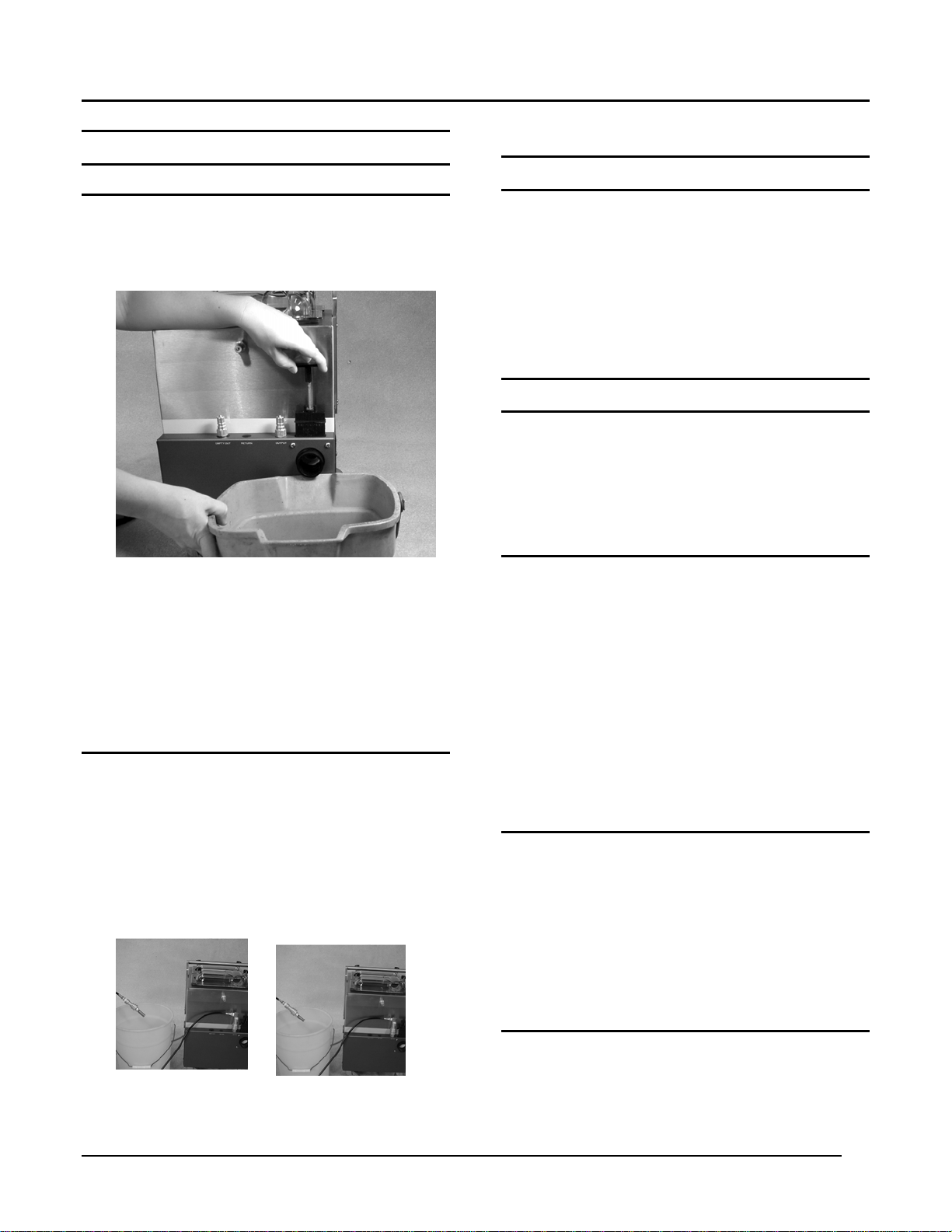
DRAINING RECOVERY TANK
1. Turn machine off.
2. Place a bucket under the drain valve and pull up
the handle (Figure 9).
3. Sediment in the bottom of the tank may be rinsed
out with the solution hose and empty-out nozzle
or with a garden hose. If particles fill the seals of
the valve, turn the vacuum on and slowly close
the valve a few times to vacuum them out. This
same procedure will remove any solution
remaining in the drain valve and prevent dripping.
DRAINING SOLUTION TANK
1. Turn on vacuum and remove water from solution
tank. If dry cleaning solution is remaining in
solution tank and it is to be saved, then perform
step 2 instead.
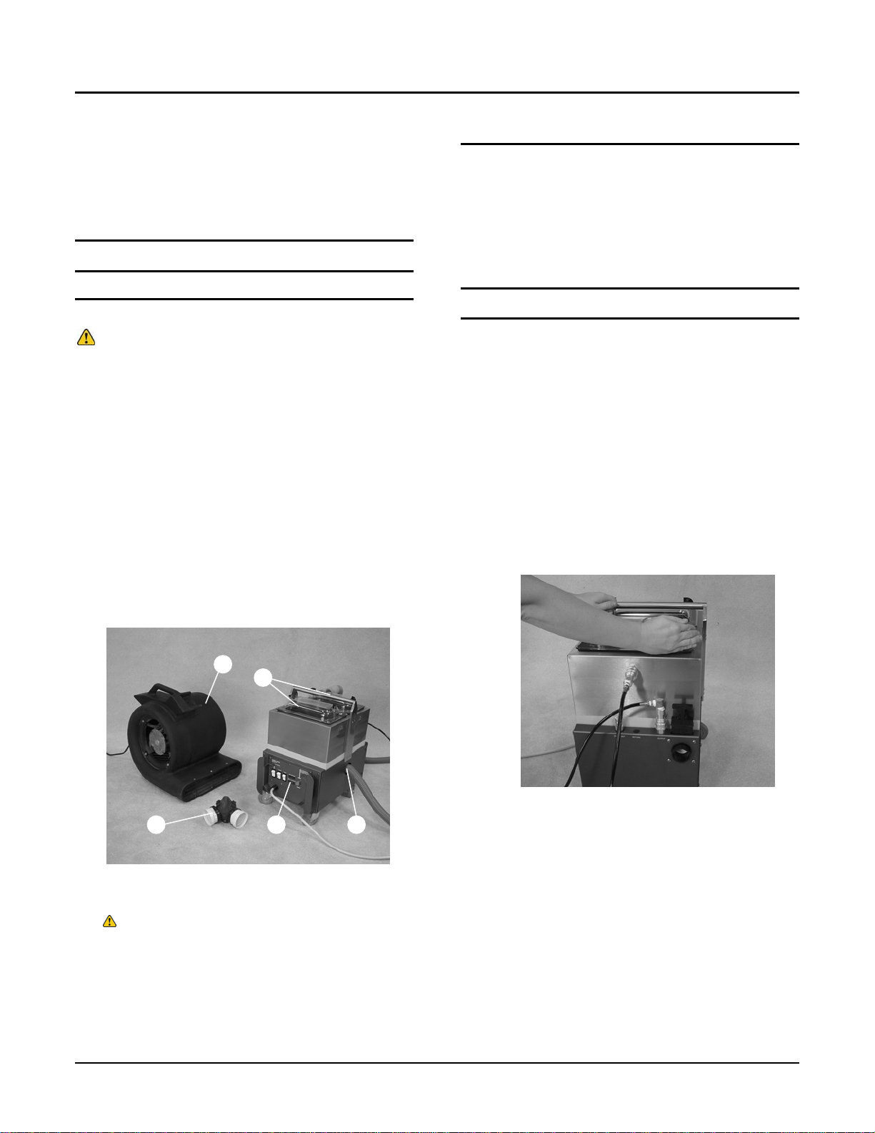
2. Remove empty-out nozzle from side of machine
FREEZE PROTECTION
and insert into end of solution hose and pump
into container (Figure 10).
1. After draining solution tank as described in the
previous section (DRAINING SOLUTION TANK),
plug the far end of the solution hose into the
solution line purge connector located on the side
of the recovery tank (Figure 8).
2. Turn on vacuum and pump for 30 seconds. This
will fill the pump and hoses with air and prevent
freezing.
MACHINE MAINTENANCE
To keep machine in good working condition, simply
follow machine’s daily, weekly and monthly
maintenance procedures.
FOR SAFETY: When servicing machine, unplug
cord from wall outlet.
DAILY MAINTENANCE
(Every 4 Hours of Operation)
1. Empty and rinse out recovery tank thoroughly.
2. Clean vacuum filter screen.
3. When solution tank is empty, remove and clean
solution filter screen located in the bottom of the
solution tank.
4. Wipe off power cord and check for damage,
replace if necessary. Coil cord neatly after use.
5. Clean machine with an all purpose cleaner and
damp cloth.
WEEKLY MAINTENANCE
(Every 20 Hours of Operation)
1. Inspect vacuum hoses for holes and loose cuffs.
2. Inspect spray pattern for plugging. If plugged,
remove spray tips and soak them in acetic acid
solution for up to six hours. Do not use pointed
objects to unplug tips, damage will occur.
3. Lubricate female hose couplers with lightweight
oil.
MONTHLY MAINTENANCE
(Every 80 Hours of Operation)
1. Inspect vacuum and pump motors for excessive
arcing. If arcing is present replace them.
FOR SAFETY:
Fig. 9
Fig. 10

32506 (11-98) 11
2. Inspect machine for water leaks and loose
hardware. Repair immediately!

OPERATION
TROUBLE SHOOTING
PROBLEM CAUSE SOLUTION
Faulty switches or wiring. Contact Service Center
32506 (11-98)
12
.Machine does not operate.
Faulty power cord. Contact Service Center.
Building circuit breaker tripped. Reset Breaker.
Heater does not heat. Faulty switch or wiring. Contact service center.
Faulty switch or wiring. Contact Service Center.Solution pump does not operate.
Faulty solution pump motor. Contact Service Center.
Faulty pump head. Contact Service Center.
Trigger on wand not pulled. Pull Solution Trigger.
Quick couplers not fully engaged. Connect quick couplers.
Loose or broken wiring. Contact Service Center.
Faulty vacuum switch. Contact Service Center.
Vacuum motor does not
operate.
Defective vacuum motor. Contact Service Center.
Worn carbon brushes. Contact Service Center.
Recovery tank drain valve open. Close valve.Poor solution pick-up.
Defective recovery tank lid gasket. Replace gasket.
Clogged screen in vacuum tank. Remove recovery tank lid and clean
screen.
Loose vacuum hose connections. Secure cuffs to hose.
Defective vacuum hose. Replace hose.
Plugged spray tips. Clean or replace tips.Un
Improper spray tip size or spray angle. Replace with proper tips.
Worn spray tips. Replace spray tips.
Solution tank low or empty. Refill solution tank.
even or no spray.
. Contact Service Center.Faulty solution pump

OPERATION
Model 32506
LENGTH 482 mm (19 in)
WIDTH 330 mm (13 in)
HEIGHT 584 mm (23 in)
WEIGHT 21 Kg (47 lbs)
SOLUTION TANK CAPACITY 11.4 L (3 gal)
RECOVERY TANK CAPACITY 14.4 L (3.8 gal)
SOLUTION PUMP 120 V, 2.76 bar (40psi), .7A
VACUUM MOTOR 120 V, 8A, 960 W
HEATER 120 V, 10.4A, 1250 W
SEALED WATER LIFT 2350 mm (92.5 in)
TOTAL POWER CONSUMPTION 120V, 19.1A, 2292W
POWER CORD 7.6m (25 ft) 3/12
DECIBEL RATING 3 METERS (10 FT) FROM
ACHINE ON CARPET <77 db(A)
M
SPECIFICATIONS
32506 (11-98) 13
Table of contents