PA A80R Manual

1
A80R
A80R
MANUALE DI MANUTENZIONE
MAINTENANCE HANDBOOK
MANUEL D’ENTRETIEN
WARTUNGSHANDBUCH
Equipaggiamenti
Tecnici
Lavaggio
A80R-A80R2
TESTINE
ROTANTI 4
05-2008
GB
FD
I10
12.9410.80
TESTINA MATRICOLA
A80R DA 3177 COMPRESA
A80R2 DA 3176 COMPRESA
TESTINA - CLEANING HEAD - TÊTE PIVOTANTE - REINIGUNGSKOPF

2
Indica una procedura per il montaggio/smontaggio.
Indica un’operazione di verifica/manutenzione su alcune parti.
Indica accorgimenti/procedure cui prestare particolare attenzione
La testina A80R è di tipo volumetrico: il moto è dato da una turbina che gira ad altissima
velocità in rapporto alla quantità d’acqua ricevuta dagli iniettori, ed è tarata per funzionare solo
ad una certa portata.
Se varia la portata del liquido occorre adeguare la turbina con gli iniettori corretti, pena il
danneggiamento del meccanismo. Si consiglia pertanto di consultare il grafico D2 a pag. 1-3 del
manuale di istruzione per trovare la corrispondenza esatta tra portata e diametro degli iniettori,
o di rivolgersi direttamente al costruttore.
Per lo smontaggio e il rimontaggio dei seeger fare attenzione a non forzare troppo l’apertura
per evitare che perdano la loro forma originaria. Se possibile si consiglia di utilizzare una pinza
con finecorsa.
La Testina STANDARD è fornita di guarnizioni (DINAMICHE) in PTFE + O-Ring in EPDM. Lu-
brificare esclusivamente con GRASSO SILICONICO. Per l’utilizzo di liquidi detergenti, additivi
chimici ecc. non compatibili con le guarnizioni standard è indispensabile contattare il nostro
UFFICIO TECNICO. A richiesta le guarnizioni (DINAMICHE) O-RING sono disponibili anche in
diverso materiale, NBR-FFKM(kalrez)-FKM(viton). Le guarnizioni (STATICHE) sono in FKM (vi-
ton).
Durante lo smontaggio verificare sempre l’integrità e il buono stato di guarnizioni, cuscinetti
e ingranaggi. Se un elemento non è perfettamente integro e funzionante chiederne il ricambio
al costruttore.
Durante il montaggio ingrassare sempre i riporti ceramici e le guarnizioni di tenuta, utiliz-
zando grasso siliconico.
Avvertenze pag. 2
Indicazioni generali pag. 2
Smontaggio/Verifica pag. 6
Montaggio/Manutenzione pag. 16
Le operazioni descritte nel presente manuale devono essere eseguite esclusiva-
mente da personale qualificato.
Per la manutenzione programmata vedere Manuale d’istruzione alla voce Manu-
tenzione.
Indice
Avvertenze
Indicazioni generali
Simbologia utilizzata

3
Indicates a assembling/disassembling procedure.
Indicates a checking/maintenance operation on several parts.
Indicates suggestions/procedures to which particular attention should be given.
The A80R head is the volumetric type: the motion is provided by a turbine which rotates
at extremely high speed in relation to the quantity of water received by the injectors and is
calibrated to function only at a certain rate of flow.
If the flow of the liquid varies the turbine has to be adjusted with the correct injectors,
otherwise the mechanism will be damaged. Therefore we suggest consulting the diagram D2
on page 1-3 of the instruction manual to find the exact correlation between flow and diameter
of the injectors, or contact the manufacturer directly.
For disassembling and reassembling the snap rings (seeger) be careful not to force the
opening too much so that they do not lose their original shape. We advise using pliers with end
stop, if possible.
The STANDARD Tank cleaning head is supplied with seals (DYNAMIC) in PTFE + O-Ring in
EPDM. Lubricate ONLY with SILICONE GREASE. For use with Detergent liquid, Chemical addi-
tives etc that are not compatible with the standard seals, it is essential to contact our TECHNI-
CAL OFFICE for further information. On request, the O-RING seals (DYNAMIC) are available in
different materials such as NBR-FFKM(kalrez)-FKM(viton). The STATIC seals are in FKM (viton).
For programmed maintenance check the instruction book under the heading “maintenance”.
When disassembling check that the gaskets, bearings and gears are intact and in good condi-
tion. If an element is not perfectly intact and if it does not function properly request a replace-
ment from the manufacturer.
Always grease the ceramic coatings and the seal gaskets with silicon grease while assem-
bling.
Warnings page 3
General indications page 3
Disassembly/Checking page 6
Assembly/Maintenance page 16
Only qualified personnel should carry out the operations described in this ma-
nual.
For programmed maintenance check the instruction book under the heading “main-
tenance”
Table of contents
Warnings
General indications
Used symbols

4
Indique une procédure pour le montage/démontage.
Indique une opération de contrôle/entretien sur certaines parties.
Indique des précautions/procédures auxquelles il faut faire particulièrement attention.
La tête A80R est une tête de type volumétrique : le mouvement est transmis par une turbine
qui tourne à très grande vitesse par rapport à la quantité d’eau reçue par les injecteurs, et est
calibrée pour fonctionner seulement à un certain débit.
Si le débit du liquide change, il faut adapter la turbine aux injecteurs corrigés, afin de ne
pas endommager le mécanisme. Nous conseillons donc de regarder le graphique D2 à la page
1-3 du manuel d’instructions, pour trouver la correspondance exacte entre débit et diamètre
des injecteurs, ou s’adresser directement au fabricant.
Pour le démontage et le remontage des circlips, ne pas trop forcer l’ouverture afin d’éviter
qu’ils ne perdent leur forme originale. Si possible, nous conseillons d’utiliser une pince avec fin
de course.
La tête de lavage STANDARD est douée de joints (DYNAMIQUES) en PTFE + EDPM. Lubrifiez
exclusivement avec de la GRAISSE SILICONIQUE. Pour l’utilisation de liquides détergents,
additifs chimiques etc. non compatibles avec les joints standard il est indispensable de contacter
notre SERVICE TECHNIQUE. Sur demande les JOINTS TORIQUES (DYNAMIQUES) sont dispo-
nibles en d’autres matériels , à savoir : NBR, KALREZ, VITON. Les joints (STATIQUES) sont en
FKM (VITON).
Pendant le démontage, vérifier toujours si les garnitures, les roulements et les engrenages
sont intacts et en bon état. Si un élément n’est pas parfaitement intact et en bon état de mar-
che, demander une pièce de rechange au fabricant.
Pendant le montage, graisser toujours les rechargements céramiques et les joints d’étan-
chéité, en utilisant de la graisse silicone.
Avertissements page 4
Indications générales page 4
Démontage/Vérification page 6
Montage/Entretien page 16
Les opérations décrites dans ce Manuel ne doivent être exécutées que par un spé-
cialiste.
Pour l’entretien programmé voyez le Manuel d’usage et entretien sous la voix En-
tretien.
Table des matières
Avertissements
Indications générales
Symboles utilisés

5
Weist auf eine Vorgehensweise für den Ausbau/Einbau hin.
Weist auf einen Vorgang für die Überprüfung/Wartung einiger Bauteile hin.
Weist auf Maßnahmen/Vorgehensweisen hin, die in besonderer Weise beachtet werden
müssen.
Der Kopf A80R ist ein volumetrischer Kopf: Der Antrieb erfolgt durch eine Turbine, die mit
ausgesprochen hoher Geschwindigkeit in Abhängigkeit von der von den Einspritzern empfan-
genen Wassermenge dreht und die so tariert ist, dass sie nur mit einem bestimmten Durchsatz
funktioniert.
Falls der Durchsatz der Flüssigkeit variiert, so muss die Turbine mit den richtigen Einspritzern
angepasst werden, denn anderenfalls wird der Mechanismus beschädigt. Es wird daher
empfohlen, die Grafik D2 auf Seite 1-3 des Anleitungshandbuches zu konsultieren, um die
richtige Entsprechung von Durchsatz und Durchmesser der Einspritzer zu finden, oder sich direkt
an den Hersteller zu wenden.
Bei Ausbau und beim Wiedereinbau der Seegerringe darauf achten, dass sie nicht zu stark
geöffnet werden, damit sie ihre ursprüngliche Form beibehalten. Falls möglich eine Zange mit
Anschlag verwenden.
Der STANDARD Tankreiniger hat PFTE + EPDM Dichtungen (DYNAMISCHE). Ausschliesslich
mit SILIKONISCHEM FETT beschmieren. Bei Benützung von flüssigem Reiningungsmittel mie-
sche Zusatzstoffe ecc. die mit STANDARD Dichtungen nicht verträglich sind, ist es notwendig
sich mit unserer technischen Abteilung in Verbindung zu setzten. Nach Anfrage sind die DYNA-
MISCHE Dichtungen O-Ring auch in anderem Material wie NBR-KALREZ-VITON zur Verfügung.
Die (STATISCHE) Dichtungen sind in FKM (VITON).
Beim Ausbau stets die Unversehrtheit und den einwandfreien Zustand der Dichtungen, der
Lager und der Zahnräder überprüfen. Das Ersatzteil beim Hersteller anfordern, falls ein Element
nicht vollkommen unversehrt und funktionstauglich ist.
Beim Einbauen immer die Keramikauflage und die Dichtungen mit Silikonfett schmieren.
Hinweise Seite 5
Allgemeine Angaben Seite 5
Ausbau/Überaprüfung Seite 6
Einbau/Wartung Seite 16
Die im vorliegenden Handbuch beschriebenen Arbeiten dürfen ausschließlich von
qualifiziertem Personal ausgeführt werden.
Für eine programmierte Instandhaltung siehe Bedienungsanleitung.
Inhaltsverzeichnis
Hinweise
Allgemeine Angaben
Verwendete Symbole

ITALIANOENGLISHFRANÇAISDEUTSCH
6
Smontaggio/Verifica
Prima di iniziare le operazioni di smontaggio si raccomanda di allestire una morsa con protezioni in
alluminio, in modo da non danneggiare la testina.
Sistemare la testina su una morsa e svitare la giunzione con una chiave a forcella di 46 mm, come
indicato in fig.1.
Estraendo la giunzione si può accedere all’anello OR di tenuta e al filtro (fig.2).
Verificare l’integrità dell’anello di tenuta. Nel caso sia da sostituire è possibile ordinare sia il singolo
anello che la serie completa di guarnizioni.
Verificare l’integrità e la pulizia del filtro.
We advise setting up a vice with aluminum protections before starting the disassembling operations
so as not to damage the head.
Position the head on a vice and unscrew the joint with a 46 mm fork wrench, as shown in fig.1.
The O-ring and the filter can be reached by removing the joint (fig.2).
Check that the grommet is intact. If it has to be replaced, either the single ring or the complete
series of gaskets can be ordered.
Check that the filter is clean and that it is intact.
Avant de commencer les opérations de démontage, nous recommandons de préparer un étau avec
des protections en aluminium, de manière à ne pas endommager la tête.
Positionner la tête sur un étau et dévisser le joint à l’aide d’une clef à fourche de 46 mm, comme
le montre la fig.1.
En extrayant le joint, on peut accéder à la bague OR d’étanchéité et au filtre (fig.2).
Vérifier l’intégrité de la bague d’étanchéité. Si elle doit être remplacée, il est possible de commander
soit uniquement la bague, soit la série complète de garnitures.
Vérifier l’intégrité et la propreté du filtre.
Vor Beginn des Ausbaus sollte der Schraubstock mit Schutzbacken aus Aluminium ausgestattet
werden so dass der Kopf nicht beschädigt wird.
Den Kopf in einen Schraubstock einspannen und die Verbindung mit einem Gabelschlüssel zu 46
mm (wie auf Abb. 1 gezeigt) abschrauben.
Durch das Entfernen der Verbindung wird der O-Ring und der Filter zugänglich (Abb.2)
Die Unversehrtheit des Dichtungsrings überprüfen. Falls er ersetzt werden muss, so kann sowohl
der einzelne Ring, als auch der vollständige Dichtungssatz bestellt werden.
Die Unversehrtheit des Filters kontrollieren und sicherstellen, dass er sauber ist.
Disassembly/Checking
1 2

ITALIANO ENGLISH FRANÇAIS DEUTSCH
7
Per smontare il collettore svitare le 6 viti servendosi di una chiave esagonale maschio di 6 mm.
Può essere utile ruotare leggermente il collettore e servirsi di un cacciavite piatto per fare leva ed
estrarlo, facendo attenzione a non danneggiare nessun componente (fig.3).
Verificare l’integrità di tutte le guarnizioni poste tra il collettore e lo statore.
A questo punto è visibile la girante. Per estrarla utilizzare una pinza come in fig.4.
Verificare l’integrità delle alette della girante e l’usura dei riporti in ceramica del suo perno centra-
le.
Verificare l’integrità e l’usura della pasticca posta sotto la girante. In particolare i dentini superiori
non devono essere troppo consumati.
To disassemble the manifold unscrew the 6 screws using a 6 mm. hexagonal male wrench. It may
be useful to slightly rotate the manifold and use a flat screwdriver as a lever to extract it, making
sure that no component is damaged (fig.3).
Check that all the gaskets between the manifold and the stator are intact.
At this point the rotor can be seen. Use pliers to extract it as shown in fig.4.
Check the wear on the ceramic coatings of the rotor central pivot and that the rotor blades are
intact.
Check the wear of the pad under the rotor and that it is intact. In particular the upper teeth must
not be too over worn.
Pour démonter le collecteur, dévisser les 6 vis à l’aide d’une clef six-pans mâle de 6 mm. Il peut
être utile de tourner légèrement le collecteur et de se servir d’un tournevis plat comme d’un levier
et de l’extraire en faisant attention à n’endommager aucun composant (fig.3).
Vérifier l’intégrité de toutes les garnitures placées entre le collecteur et le stator.
La roue à ailettes est maintenant visible. Pour l’extraire, utiliser une pince comme le montre la
fig.4.
Vérifier l’intégrité des ailettes de la roue et l’usure des rechargements céramiques de son axe cen-
tral.
Vérifier l’intégrité et l’usure de la plaquette placée sous la roue. En particulier, les dents supérieures
ne doivent pas être trop usées.
Zum Ausbauen des Kollektors die 6 Schrauben mit einem Inbusschlüssel zu 6 mm lösen. ES kann
nützlich sein, den Kollektor leicht zu drehen und mit einem Schraubenzieher zu hebeln, um ihn zu
lösen; dabei darauf achten, dass kein Bauteil beschädigt wird (Abb.3).
Die Unversehrtheit alle Dichtungen zwischen Kollektor und Stator überprüfen.
An diesem Punkt ist der Läufer sichtbar. Zum Herausnehmen eine Zange wie auf Abb. 4 verwen-
den.
Die Unversehrtheit der Rippen des Läufers und die Abnutzung der Keramikauflage seines zentralen
Bolzens überprüfen.
Die Unversehrtheit und die Abnutzung des Belags unter dem Läufer kontrollieren. Insbesondere
Démontage/Vérification Ausbau/Überprüfung
3 4

ITALIANOENGLISHFRANÇAISDEUTSCH
8
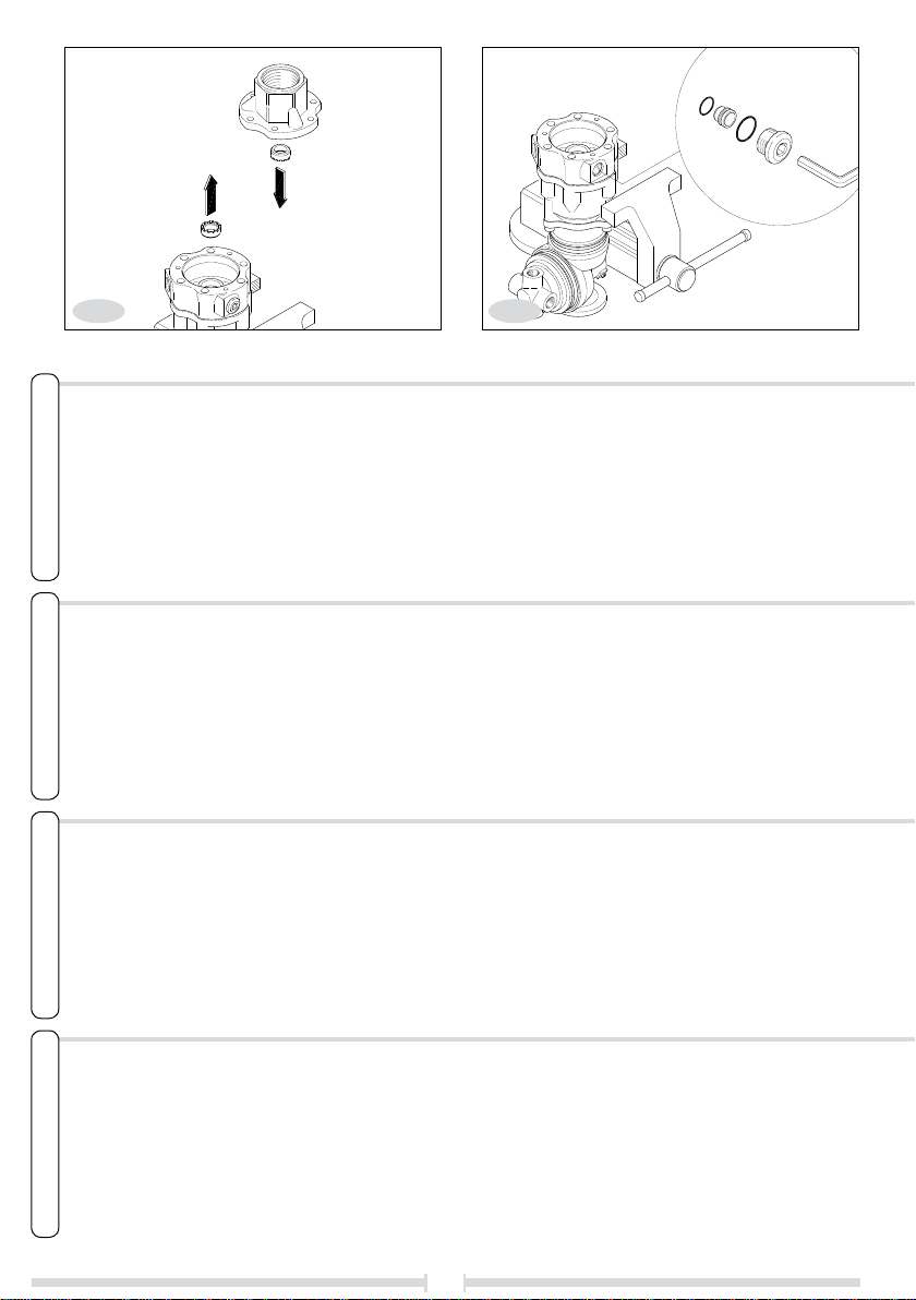
Verificare l’integrità e l’usura delle boccole (fig.5) del collettore e dello statore. Se i dentini sono
usurati procedere all’estrazione e alla sostituzione.
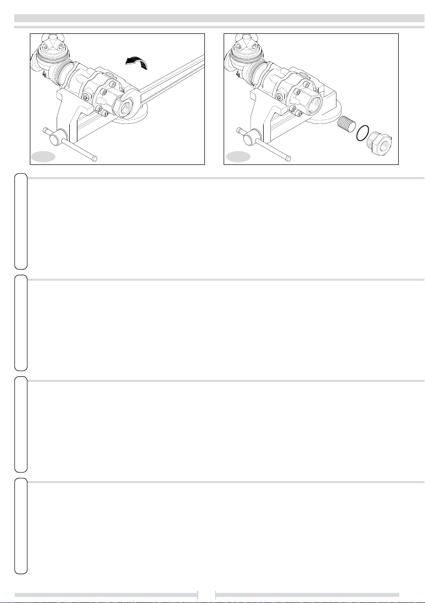
Smontare gli iniettori svitando il tappo come in fig.6, ed eventualmente spingendo dall’interno dello
statore con un utensile.
Verificare l’integrità degli iniettori e dei relativi anelli di tenuta.
Gli iniettori esistono di diverse misure, a seconda dell’utilizzo della testina. Accertarsi di sostituirli
con altri della stessa misura, e che siano adeguati alla portata dell’acqua a cui è collegata.
Togliere lo statore tirandolo verso l’alto come in fig.7. Se necessario aiutarsi ruotandolo ed even-
tualmente facendo leva con un cacciavite piatto.
Verificare l’integrità dell’anello di tenuta posto alla base dello statore.
Check the wear of the manifold and stator bushings (fig.5) and that they are intact. If the teeth are
worn remove and replace them.
Disassemble the injectors by unscrewing the cap as shown in fig.6 and if necessary pushing from
inside the stator with a tool.
Check that the injectors and the relative grommets are intact.
There are various sized injectors, according to the use of the head. Make sure that they are replaced
with those of the correct size and that they are adjusted to the flow of the water they are connected
to.
Remove the stator by pulling it upwards as shown in fig.7. If necessary help by rotating it and
levering it with a flat screwdriver.
Check that the grommet at the base of the stator is intact.
Vérifier l’intégrité et l’usure des douilles (fig.5) du collecteur et du stator. Si les dents sont usées,
procéder à l’extraction et à la substitution.
Démonter les injecteurs en dévissant le bouchon comme le montre la fig.6, et éventuellement en
poussant de l’intérieur du stator avec un outil.
Vérifier l’intégrité des injecteurs et des joints d’étanchéité correspondants.
Les injecteurs existent de plusieurs mesures, suivant l’utilisation de la tête. Veiller à les remplacer
par d’autres de la même mesure, et qui soient adaptés au débit d’eau auquel elle est reliée.
Enlever le stator en le tirant vers le haut comme le montre la fig.7. Si besoin est, s’aider en le
tournant et éventuellement en se servant d’un tournevis plat comme levier.
Vérifier l’intégrité du joint d’étanchéité placé à la base du stator.
Die Unversehrtheit und die Abnutzung der Buchsen (Abb.5) des Kollektors und des Stators über-
prüfen. Ausbauen und ersetzen, falls die Zähne abgenutzt sind.
Den Stopfen abschrauben wie auf Abb. 6 gezeigt, und die Einspritzer ausbauen, und gegebenenfalls
den Stator mit einem Werkzeug nach innen schieben.
Die Unversehrtheit der Einspritzer und der entsprechenden Dichtungsringe überprüfen.
Die Einspritzer sind in Abhängigkeit von der Verwendung des Kopfes in verschiedenen Größen
vorhanden. Sicherstellen, dass sie durch solche von der gleichen Größe ersetzt werden, und dass
sie für den angeschlossenen Wasserdurchsatz geeignet sind.
Den Stator nach oben herausziehen, wie auf Abb. 7 gezeigt. Falls erforderlich drehen und mit einem
flachen Schraubenzieher hebeln.
Die Unversehrtheit des Dichtungsrings an der Basis des Stators überprüfen.
5 6

ITALIANO ENGLISH FRANÇAIS DEUTSCH
9
A questo punto risultano visibili i satelliti superiori. Per estrarli servirsi di una pinza come in fig.8,
facendo attenzione a non danneggiare i denti. I satelliti sono disposti su tre piani col relativo por-
tasatellite. Questa operazione pertanto è da ripetere per ognuno.
Per ogni satellite è necessario verificare: l’usura del diametro interno (accertarsi che non sia ecces-
sivo il gioco una volta montato sul suo perno), l’usura e l’integrità dei denti.
Del portasatellite occorre verificare l’usura dei tre perni superiori e lo stato dei denti nella parte
inferiore.
I due portasatelliti superiori sono dotati di una pasticca (A, fig.8) che li distanzia dal portasatellite
che sta sotto. Anche questa deve essere verificata.
At this point the upper pinions can be seen. To extract them use pliers as shown in fig.8, being careful
not to damage the teeth. The pinions are positioned on three levels with relative pinion-carriers.
Therefore this operation has to be repeated for each one.
Check the following for each pinion: the wear of the internal diameter (make sure that the slack
is not excessive after it has been mounted on its pivot), the wear of the teeth and that they are
intact.
Check the wear of the upper three pivots of the pinion-carrier and the state of the teeth in the lower
part.
The two upper pinion-carriers are equipped with a pad (A, fig.8) that separates them from the
pinion-carrier which is below. This also has to be checked.
Les satellites supérieurs sont maintenant visibles. Pour les extraire, se servir d’une pince comme le
montre la fig.8 en veillant à ne pas abîmer les dents. Les satellites sont disposés sur trois étages
avec leur porte-satellite. Cette opération doit donc être répétée pour chacun.
Pour chaque satellite, il faut vérifier : l’usure du diamètre interne (s’assurer qu’il n’y a pas de jeu
excessif une fois monté sur son axe), l’usure et l’intégrité des dents.
Sur le porte-satellite, il faut vérifier l’usure des trois axes supérieurs et l’état des dents dans la
partie inférieure.
Les deux porte-satellites supérieurs sont munis d’une plaquette (A, fig.8) qui les espace du porte-
satellite qui se trouve dessous. Celle-ci aussi doit être contrôlée.
An diesem Punkt sind die oberen Satelliten sichtbar. Zum Herausziehen eine Zange verwenden wie
auf Abb. 8 gezeigt und darauf achten, dass die Zähne nicht beschädigt werden. Die Satelliten sind
mit der entsprechenden Halterung auf drei Ebenen angeordnet. Dieser Vorgang muss daher für die
von ihnen wiederholt werden.
Bei jedem Satelliten müssen überprüft werden: die Abnutzung des Innendurchmesser (sicherstellen,
dass nach dem Einbau auf dem Bolzen nicht zu viel Spiel vorhanden ist), die Abnutzung sowie die
Unversehrtheit der Zähne.
An der Satellitenhalterung müssen die Abnutzung der drei oberen Bolzen und der Zustand der Zähne
im unteren Teil überprüft werden.
Die beiden oberen Satellitenhalterungen weisen einen Belag auf (A, Abb.8), der den Abstand zu
dem darunter befindlichen Satellitenhalterung herstellt. Auch dieser muss überprüft werden.
78

ITALIANOENGLISHFRANÇAISDEUTSCH
10
I satelliti superiori, ruotando a velocità più elevate, sono maggiormente soggetti ad usura. E’ con-
sigliabile quindi effettuare una “rotazione” dei gruppi di satelliti all’atto del montaggio, invertendo
primo e l’ultimo gruppo (vedere “montaggio/manutenzione).
Verificare lo stato dei denti interni alla corona (di norma non dovrebbero avere problemi).
Svitare le tre viti con una chiave esagonale maschio di 5 mm per smontare la corona dal resto.
Visionare lo stato della guarnizione inserita nel foro alla base della corona. Smontarla solo se usurata
o rotta, in quanto l’estrazione ne comporta l’inevitabile rottura.
Se è necessario togliere la guarnizione, occorre utilizzare un utensile appuntito in modo da fare leva
tra la sede e la guarnizione stessa, piegandola (fig.10).
Die oberen Satelliten drehen sich mit ausgesprochen hoher Geschwindigkeit und sind daher einem
größeren Verschleiß ausgesetzt. Daher wird empfohlen, bei Einbau eine “Rotation” der Satellitengrup-
pen vorzunehmen und die erste mit der letzten Gruppe zu vertauschen (siehe “Einbau/Wartung”).
Den Zustand der inneren Zähne der Krone überprüfen (sollten normalerweise keine Probleme
aufweisen).
Die drei Schrauben mit einem Inbusschlüssel zu 5 mm lösen, um die Krone vom Rest zu lösen.
Den Zustand der Dichtung überprüfen, die in die Bohrung an der Basis der Krone eingesetzt ist. Nur
ausbauen, falls sie abgenutzt oder beschädigt ist, da sie beim Herausnehmen unvermeidlicherweise
zerstört wird.
The upper pinions, rotating at higher speeds, are subject to greater wear. Therefore we advise car-
rying out a “rotation” of the pinion groups when assembling, inverting the first and the last group
(see “assembling/maintenance).
Check the condition of the teeth inside the crown (generally they do not have any problems).
Unscrew the three screws with a 5 mm. hexagonal male wrench to disassemble the crown from the
rest.
Inspect the state of the gasket inserted in the hole at the base of the crown. Disassemble it only if
it is worn or broken, as it breaks if it is extracted.
If it is necessary to remove the gasket, use a pointed tool to lever between the seat and the gasket
itself, bending it (fig.10).
Les satellites supérieurs, en tournant plus vite, sont davantage sujets à usure. Nous conseillons
donc d’effectuer une “rotation” des groupes de satellites au moment du montage, en inversant le
premier et le dernier groupe (voir “montage/entretien”).
Vérifier l’état des dents internes de la couronne (en théorie, elles ne devraient présenter aucun
problème).
Dévisser les trois vis à l’aide d’une clef six-pans mâle de 5 mm pour démonter la couronne du
reste.
Contrôler l’état du joint introduit dans le trou à la base de la couronne. Ne le démonter que s’il est
usé ou cassé, car l’extraction le casserait de toute façon.
910

ITALIANO ENGLISH FRANÇAIS DEUTSCH
11
Per estrarre il gruppo rotazione degli ugelli bisogna allentare le due viti con una chiave a forcella di
8 mm, dopodichè se necessario dare alcuni colpetti con un martello di plastica per sbloccare l’albero
dalla sua sede, (fig.11).
Verificare l’integrità dei due anelli OR posti all’interno della sede dell albero.
Per estrarre il perno fissare in morsa il gruppo rotazione e con l'aiuto di due cacciaviti rimuovere
l'anello spiroidale come mostrato in fig.12
To remove the rotating nozzle unit you have to loosen the two screws with an 8 mm open ended
spanner, then if it is necessary, hit it lightly a few times with a plastic hammer to unblock the shaft
from its casing (fig.11).
Check that the two O-rings inside the shaft casing are intact.
To remove the pin, fix the rotating unit in a vice and with the aid of two screwdrivers remove the
spiral shaped ring as shown in fig.12
Si besoin est, enlever le joint. Il faut utiliser un outil pointu de manière à s’en servir comme levier
entre le joint et son logement en pliant le joint (fig.10).
Pour extraire le groupe rotation des tuyères, desserrer les deux vis à l'aide d'une clef à griffe de 8
mm, après quoi, si besoin est, donner quelques coups avec un marteau en plastique pour débloquer
l’arbre de son logement (fig.11).
Vérifier l’intégrité des deux bagues OR positionnées à l’intérieur du logement de l’arbre.
Pour extraire le goujon, fixer le groupe de rotation dans l'étau et avec deux tournevis, enlever la
bague spiroïdale comme le montre la fig.12.
Falls die Dichtung herausgenommen werden muss, so muss ein spitzes Werkzeug verwendet werden,
mit dem zwischen dem Sitz und der Dichtung selbst gehebelt wird (Abb.10).
Um das Rotationsaggregat der Düsen herauszunehmen, muss man die beiden Schrauben mit einem
8 mm-Maulschlüssel lockern und falls erforderlich anschließend mit einem Kunststoffhammer leicht
klopfen, um die Welle aus ihrem Sitz zu lösen (Abb.11) .
Die Unversehrtheit der beiden O-Ringe im Inneren des Sitzes der Welle überprüfen.
Um den Zapfen herauszunehmen, das Rotationsaggregat im Schraubstock festhalten und mit Hilfe
von zwei Schraubenziehern den Spiralring, wie in Abb.12 gezeigt, entfernen.
11 12

ITALIANOENGLISHFRANÇAISDEUTSCH
12
Una volta rimosso l'anello spiroidale è possibile sfilare l'anello inox e la guarnizione composta da
due elementi (fig.13)
Se dopo aver verificato lo scorrimento dei cuscinetti, si sospetta che siano danneggiati, togliere
l'anello torico che tiene i due cuscinetti fermi sul perno, mettendolo in morsa ed aiutandosi con due
pinze per allargarlo, e un cacciavite per sollevarlo (fig.14).
Nachdem der Spiralring entfernt wurde, ist es möglich, den Edelstahlring und die Dichtung, die aus
zwei Elementen besteht, herauszunehmen (Abb.13).
Wenn man nach Überprüfung des Gleitens der Lager den Verdacht hat, dass sie beschädigt sind,
den Runddichtring entfernen, der die beiden Lager fest auf dem Zapfen hält, indem man ihn in
einen Schraubstock steckt und sich mit zwei Zangen behilft, um ihn auszuweiten und mit einem
Schraubenzieher, um ihn anzuheben (Abb.14).
Once this spiral ring has been removed the stainless steel ring and the two-element seal can be
removed (fig.13)
If, after having checked the smooth movement of the bearings you suspect they are damaged,
remove the toric ring that is locking the bearings on the pin, putting it in a vice and using two pliers
to widen it and a screwdriver to lift it (fig.14).
De l’intérieur de la tête pivotante, il est ensuite possible d’enlever la bague en inox et la garniture
composée de deux éléments (voir fig.13/1).
Si après avoir vérifié le coulissement des roulements on suspecte qu’ils sont endommagés, enlever
le circlip qui tient les deux roulements fixés sur le pivot, et les extraire pour les contrôler de façon
plus approfondie (fig.13/2).
13 14

ITALIANO ENGLISH FRANÇAIS DEUTSCH
13
Estrarre i cuscinetti dall'albero per una verifica o sostituzione (fig.15).
Verificare che il riporto ceramico dell’albero sia integro.
Sulla testina rotante è rimasta una guarnizione che si può sfilare (fig.16) per verificarne l’integrità.
Occorre ora verificare gli ugelli e gli eventuali tappi, svitandoli dal rispettivo filetto sulla testina ed
estraendo dall’interno di ognuno il convogliatore a farfalla (B).
Attenzione, sulla testina rotante possono essere montati diversi tipi di ugelli in diverse modalità,
secondo determinati criteri. Vedere la sezione “Montaggio/Manutenzione” per ulteriori istruzioni.
Montare gli ugelli in modo non adeguato può danneggiare il meccanismo.
Extraire les roulements de l'arbre pour un contrôle ou une substitution (fig.15).
Vérifier si le rechargement céramique de l’arbre est intact.
Sur la tête pivotante, une garniture est restée; on peut l’enlever (fig.16) pour vérifier son intégri-
té.
Il faut maintenant vérifier les buses et les éventuels bouchons, en les dévissant de leur filetage
respectif sur la tête et en extrayant de l’intérieur de chacun d’eux le convoyeur à ailettes (B).
Attention, sur la tête pivotante plusieurs types de convergents peuvent être montés en différen-
tes modalités, suivant certains critères. Voir la section “Montage/Entretien” pour avoir davantage
d’explications. Monter les convergents de manière inadéquate peut endommager le mécanisme.
Remove the bearings from the shaft either to check or change (fig.15).
Check that the ceramic coating of the shaft is intact.
There is still a gasket on the rotating head that can be pulled out (fig.16) to check that it is in-
tact.
Now it is necessary to check the nozzles and caps, by unscrewing them from the respective thread
on the head and removing the throttle conveyor (B) from inside each one.
Attention, different types of nozzles can be mounted on the rotating head in different ways, according
to certain criteria. See the section “Assembling/Maintenance” for further instructions. Assembling
the nozzles incorrectly can damage the mechanism.
Die Lager für eine Überprüfung oder ein Ersetzen von der Welle entfernen (Abb.15).
Sicherstellen, dass die Keramikauflage der Welle unversehrt ist.
Auf dem rotierenden Kopf ist eine Dichtung (Abb.16) geblieben die zur Überprüfung der Unversehr-
theit abgezogen werden kann.
Nun müssen die Düsen und die eventuellen Stopfen überprüft werden; dazu werden aus dem ent-
sprechenden Gewinde am Kopf herausschrauben und aus dem Innern eines jeden Drosselförderers
(B) herausnehmen.
Achtung: Auf dem rotierenden Kopf können in Abhängigkeit von bestimmten Kriterien verschiedene
Düsentypen auf unterschiedliche Weise montiert sein. Siehe den Abschnitt “Einbau/Wartung” für
weitere Anweisungen. Durch den Einbau ungeeigneter Düsen kann der Mechanismus beschädigt
werden.
15 16
B

ITALIANOENGLISHFRANÇAISDEUTSCH
14
Per togliere il gruppo pignone occorre mettere in morsa la testina, riscaldare abbondantemente la
zona filettata interna, e svitare l'albero con un cacciaspine e un tubo come indicato in fig.17.
Una volta svitato l'albero è possibile estrarre il gruppo pignone dalla base, e sfilare il perno dalla
sua sede (fig.18).
Verificare lo stato dell’anello OR montato sull’albero.
Verificare che la dentatura interna all’albero verticale non sia danneggiata, e la buona condizione
del riporto ceramico.
To remove the pinion unit put the head in a vice, warm the inside threaded area thoroughly and
loosen the shaft with a pin punch and tube as illustrated in fig.17.
Once the shaft has been loosened the pinion unit can be removed from the base and the pin taken
out (fig.18).
Check the condition of the O-ring mounted on the shaft.
Check that the toothing inside the vertical shaft is not damaged and that the ceramic coating is in
good condition.
Pour enlever le groupe pignon, mettre la tête dans l'étau, réchauffer fortement la zone filetée interne,
et dévisser l'arbre au moyen d'un chasse-goupilles et d'un tube, comme le montre la fig.17.
Après avoir dévissé l'arbre, il est possible d'extraire le groupe pignon de la base, et de dégager le
goujon de son logement (fig.18).
Vérifier l’état de la bague OR montée sur l’arbre.
Vérifier si la denture à l’intérieur de l’arbre vertical est endommagée et si le rechargement céramique
est en bon état.
Für das Entfernen des Ritzelaggregats, muss man den Kopf in einen Schraubstock stecken, den
inneren Gewindebereich gut anwärmen und die Welle mit einem Schraubenzieher und einem Rohr,
wie in Abb.17 gezeigt, losschrauben.
Nachdem die Welle losgeschraubt ist, kann man das Ritzelaggregat vom Untergestell entfernen und
den Zapfen aus seinem Sitz nehmen (Abb.18).
Den Zustand des auf der Welle montierten O-Rings überprüfen.
Sicherstellen, dass die innere Zahnung der vertikalen Welle nicht beschädigt ist, und den einwan-
dfreien Zustand der Keramikauflage sicherstellen.
17 18

ITALIANO ENGLISH FRANÇAIS DEUTSCH
15
Ora è possibile visionare i cuscinetti e la guarnizione della base del pignone per una verifica
(fig.19).
Dalla cavità interna è possibile togliere i due anelli OR per verificarli (fig.20).
Now the bearings and the gasket can be seen from the base of the pinion for checking (fig.19).
Check the condition of the O-ring mounted on the shaft (fig.20).
Il est maintenant possible de voir les roulements et la garniture de la base du pignon pour procéder
à un contrôle (fig.19).
Vérifier l’état de la bague OR montée sur l’arbre (fig.20).
Nun können die Lager und die Dichtungen der Basis des Ritzels überprüft werden (Abb.19).
Den Zustand des auf der Welle montierten O-Rings überprüfen (Abb.18).
19 20

ITALIANOENGLISHFRANÇAISDEUTSCH
16
Durante il montaggio è importante ingrassare sempre le seguenti parti:
- sedi cilindriche
- riporti in ceramica
- anelli di tenuta
Per l’ingrassaggio di qualsiasi parte usare solo l’apposito grasso siliconico.
Inserire i cuscinetti sul perno fino a battuta. Se necessario servirsi di un tubo e un martello per
spingerli con maggiore forza. Il tubo deve avere un diametro interno uguale o leggermente superiore
al diametro interno del cuscinetto (fig.21). Fermare i cuscinetti con l'anello torico.
Ingrassare tutti gli anelli e le guarnizioni con sede nel pignone indicato in fig.22.
It is important to grease the following parts when assembling:
- cylindrical seats
- ceramic coatings
- grommets
Only use the special silicon grease to grease any part.
Insert the bearings on the pivot up to the beat. If necessary use a tube and a hammer to push them
with greater force. The internal diameter of the tube must be the same or slightly more than the
internal diameter of the bearing in fig.21). Lock the bearings with the toric ring.
Grease all the rings and the gaskets with seat in the pinion indicated in fig.22.
Pendant le montage, il est important de graisser à chaque fois les parties suivantes :
- les logements cylindriques
- les rechargements céramiques
- les bagues d’étanchéité
Pour le graissage de toutes les parties, se servir de graisse silicone.
Introduire les roulements sur le pivot jusqu’à la butée. Si besoin est, se servir d’un tube et d’un mar-
teau pour les pousser avec plus de force. Le tube doit avoir un diamètre interne égal ou légèrement
supérieur au diamètre interne du roulement (fig.21). Arrêter les roulements avec le joint torique.
Graisser toutes les bagues et les garnitures avec logement dans le pignon indiqué sur la fig.22.
Beim Einbau müssen die folgenden Bauteile immer geschmiert werden:
- zylindrische Sitze
- Keramikauflagen
- Dichtungsringe
Zum Schmieren aller Bauteile ausschließlich das entsprechende Silikonfett verwenden.
Die Lager bis zu Anschlag auf den Bolzen aufsetzen. Falls erforderlich ein Rohr und einen Hammer
verwenden, um sie mit größerer Kraft zu schieben. Das Rohr muss einen Innendurchmesser aufwei-
sen, der dem Innendurchmesser der Lager entspricht oder leicht größer ist (Abb.21). Die Lager mit
dem Runddichtring befestigen.
Alle Ringe und die Dichtungen mit Sitz im auf Abb. 22 gezeigten Ritzel schmieren.
Montaggio/Manutenzione Assembly/Maintenance
21 22

ITALIANO ENGLISH FRANÇAIS DEUTSCH
17
Inserire gli anelli e le guarnizioni nelle loro sedi, inserire l’albero e fare pressione per unire il tutto.
E’ probabile che occorra una morsa (fig.23), o un martello. Fare attenzione che i cuscinetti entrino
nelle loro sedi senza forzare eccessivamente.
Verificare il libero scorrimento dell’albero nei cuscinetti una volta montato.
Bloccare il gruppo con l’anello spiroidale (fig.24).
Insert the rings and the gaskets in their seats, insert the shaft and press all together. You could
probably need a vice (fig.23) or a hammer. Make sure that the bearings enter their seats without
forcing excessively.
Check that the shaft slides freely in the bearings when it has been mounted.
Lock the unit with the spiral-shaped ring (fig.24).
Introduire les bagues et les garnitures dans leurs logements, introduire l’arbre et faire appuyer pour
unir le tout. Il est probable qu’il faille utiliser un étau (fig.23) ou un marteau. Veiller à ce que les
roulements entrent dans leurs logements sans trop forcer.
Vérifier la liberté de glissement de l’arbre dans les roulements après le montage.
Bloquer le groupe avec la bague spiroïdale (fig.24).
Die Ringe und die Dichtungen in ihre Sitze einsetzen, die Welle einsetzen und Druck ausüben, um
alles zu verbinden. Es ist wahrscheinlich, dass ein Schraubstock (Abb.23) oder ein Hammer ve-
rwendet werden muss. Darauf achten, dass die Lager ohne zu große Kraft in ihre Sitze eintreten.
Sicherstellen, dass die Welle nach dem Einbauen in die Lager ungehindert gleitet.
Das Aggregat mit dem Spiralring sperren (Abb.24).
Montage/Entretien Einbau/Wartung
23 24

ITALIANOENGLISHFRANÇAISDEUTSCH
18
Inserire i cuscinetti all’interno del pignone e l’anello di tenuta alla sua base come indicato in
fig.25
Infilare l'albero nei cuscinetti all'interno del pignone.
Mettere l'anello di tenuta sull'albero, e applicare loctite 270 sul filetto (fig.26).
Avvitare il pignone con l'albero alla base.
Inserire nelle sedi interne dell’albero gli anelli di tenuta ed ingrassarli come indicato in fig.27.
Insert the bearings inside the pinion and the grommet at its base as shown in fig.25.
Insert the shaft in the bearings inside the pinion.
Fit the sealing ring on the shaft and spread some Loctite 270 on the thread (fig.26).
Tighten the pinion with the shaft onto the base.
Insert the grommets in the internal seats of the shaft and grease them as indicated in fig.27.
Introduire les roulements à l’intérieur du pignon et la bague d’étanchéité à sa base comme le montre
la fig.25.
Enfiler l'arbre dans les roulements à l'intérieur du pignon.
Mettre la bague d'étanchéité sur l'arbre et appliquer du loctite 270 sur le filet (fig.26).
Visser le pignon avec l'arbre à la base.
Introduire dans les logements internes de l’arbre les bagues d’étanchéité et les graisser comme le
montre la fig.27.
25 26
Die Lager in das Innere des Ritzels und den Dichtungsring in seine Basis einsetzen, wie auf Abb. 25
gezeigt.
Die Welle in die Lager innerhalb des Ritzels stecken.
Den Dichtungsring auf die Welle stecken und Loctite 270 auf das Gewinde aufbringen (Abb.26).
Das Ritzel mit der Welle am Untergestell festschrauben.
Die Dichtungsringe in die inneren Sitze der Welle einsetzen und schmieren, wie auf Abb. 27 gezei-
gt.

ITALIANO ENGLISH FRANÇAIS DEUTSCH
19
Montare il gruppo perno-portaugelli nel suo alloggio sull’albero verticale (aiutandosi con un mar-
tello di plastica se necessario) fino a che i due ingranaggi conici non siano perfettamente incastrati
(fig.28).
Il gioco tra i due ingranaggi deve essere praticamente nullo. Verificare quindi il libero scorrimento
ruotando uno dei due alberi. Se lo scorrimento non è omogeneo (e i cuscinetti sono stati verificati)
o è presente del gioco, tentare di inserire meglio l’albero, tenendo presente che la parte posteriore
arriva circa a battuta con la fine della sede.
Fissare l’albero tramite le due viti (fig.28).
Mount the pivot-nozzle-holder group in its seat on the vertical shaft (using a plastic hammer if
necessary) so that the two conical gearings match perfectly (fig.28).
The slack between the two gearings must be practically null. Therefore check that they move freely
by rotating one of the two shafts. If they do not moving smoothly (and the bearings have been
checked) or if there is slack, try to insert the shaft better, remembering that the rear part reaches
approximately the beat with the end of the seat.
Fix the shaft with the two screws (fig.28).
Monter le groupe pivot-porte-buses dans son logement sur l’arbre verticale (à l’aide d’un marteau en
plastique si besoin est) jusqu’à ce que les deux engrenages coniques soient parfaitement encastrés
(fig.28).
Le jeu entre les deux engrenages doit être pratiquement nul. Vérifier ensuite le bon glissement en
tournant un des deux arbres. Si le glissement n’est pas homogène (et que les roulements ont été
contrôlés) ou s’il y a du jeu, essayer de mieux introduire l’arbre, en tenant compte du fait que la
partie arrière arrive environ en battue avec la fin du logement.
Fixer l'arbre à l'aide des deux vis (fig.28).
27 28
Die Bolzen- und Düsenhalterungsgruppe in ihren Sitze auf der vertikalen Welle einsetzen; dabei
falls erforderlich einen Kunststoffhammer verwenden, bis die beiden konischen Zahnräder perfekt
sitzen (Abb.28).
Das Spiel zwischen den beiden Zahnrädern muss praktisch Null sein. Dann sicherstellen, dass sie
beim Drehen einer der beiden Welle ungehindert gleiten. Falls das Gleiten nicht homogen (und die
Lager überprüft worden sind) ist oder falls Spiel vorhanden ist, so muss versucht werden, die Welle
besser einzusetzen, wobei zu berücksichtigen ist, dass sich der hintere Teil ungefähr in Anschlag
mit dem Sitz befinden muss.
Die Welle mit den beiden Schrauben festschrauben (Abb.28).

ITALIANOENGLISHFRANÇAISDEUTSCH
20
Ingrassare la parte ceramizzata dell’albero come in fig.29.
Se precedentemente è stato smontata anche la guarnizione in due pezzi alla base della corona, la
parte interna di questa (in teflon) deve necessariamente essere sostituita con un nuovo ricambio,
in quanto non è possibile smontarla senza danneggiarla.
Per montare la guarnizione della corona occorre inserire prima l’anello OR (più grande) nel suo
alloggio all’interno della corona stessa. Dopodichè, piegandolo facendo pressione come indicato in
fig.30 si inserisce l’altro anello (in teflon, di ø più piccolo).
29 30
Grease the ceramic part of the shaft as shown in fig.29.
If the gasket at the base of the crown has also been previously disassembled in two pieces, the
internal part of this (in Teflon) must be replaced with a new part, as it is not possible to disassemble
it without damaging it.
To mount the gasket of the crown, first the O-ring (the bigger one) has to be inserted in its seat
inside the crown itself. After this, bending it, and pressing as indicated in fig.30, the other ring is
inserted (in Teflon, the smaller ø ).
Graisser la partie rechargée en céramique de l’arbre comme le montre la fig.29.
Si auparavant la garniture a été aussi démontée en deux pièces à la base de la couronne, la partie
interne de cette dernière (en téflon) doit obligatoirement être remplacée par une nouvelle pièce de
rechange, car il n’est pas possible de la démonter sans l’abîmer.
Pour monter la garniture de la couronne, il faut introduire d’abord la bague OR (plus grande) dans
son logement à l’intérieur de la couronne. Après quoi, en la pliant et en appuyant comme le montre
la fig.30, on introduit l’autre bague (en téflon, d’un diamètre inférieur).
Den Keramikteil der Welle schmieren, wie auf Abb. 29 gezeigt.
Falls zuvor auch die Dichtung der beiden Teile an der Basis der Krone ausgebaut worden ist, so
muss der innere Teile (aus Teflon) unbedingt durch ein neues Ersatzteil ersetzt werden, da er nicht
ohne Beschädigung ausgebaut werden kann.
Beim Einbauen der Dichtung der Krone muss zuerst der (größere) O-Ring in seinen Sitz im Innern
der Krone selbst eingesetzt werden. Anschließend wird wie auf Abb. 30 unter Druck biegen und den
anderen Ring (aus Teflon, mit kleinerem Durchmesser) eingesetzt.
Other manuals for A80R
1
This manual suits for next models
1
Table of contents
Other PA Ultrasonic Jewelry Cleaner manuals
Popular Ultrasonic Jewelry Cleaner manuals by other brands

Bissell
Bissell BigGreen Commercial Hercules Scrub & Clean... Care and use instructions

Makita
Makita CL003G instruction manual

Kärcher
Kärcher BR 30/1 C Bp Original instructions

i-team
i-team i-dose user manual

Magnasonic
Magnasonic mguc500 user manual

CHICAGO
CHICAGO 93252 Assembly and operating instructions