Kleinn 6260 User manual

Model 6260
120 PSI Compressor with 0.5 Gallon Air Tank
12V C
IMPORTANT:
It is essential that you and any other
operator of this product read and
understand the contents of this manual
before installing and using this product.
USER MANUAL
SAVE THIS MANUAL FOR FUTURE REFERENCE

Model 6260
Components:
1 0.5 gallon, 5-port a r tank
1 Model 6250RC compressor
1 Package #1 - a r f tt ngs
1 Package #2 - nstallat on hardware
(Please check to make sure that you have two labeled packages in your kit. Each
package contains the parts needed for specific areas of onboard air installation, and
may contain smaller bags within each package labeled for specific use.)
PARTS PACKAGES
Package #1 – Air Tank Fittings
Qty 1 1/8” NPT Pressure Sw tch (90 PSI on, 120 PSI off)
Qty 1 1/4” NPT 145 PSI max. Safety Valve
Qty 1 1/4”M x 1/8”F Reducer
Qty 1 1/4” NPT Compress on F tt ng
Qty 1 ¼” Dra n Cock
Package #2 – Compressor & Tank Installation
Qty 4 13/64” Nuts, shorter bolts, washers & lock ng washers
(Compressor mount ng hardware)
Qty 1 Remote Mount A r F lter Assembly
Qty 1 Remote Mount a r f lter f tt ng
Qty 1 Replacement a r f lters
Qty 1 Remote Mount A r F lter Cl p
Qty 1 A r l ne for remote mount ng a r f lter
Qty 2 Nuts, bolts, washers – (A r tank mount ng hardware)

0.5 Gallon Air Tank Installation
Your a r tank comes w th f ve 1/4” NPT port open ngs. To nsure safe and trouble-free
use of your a r tank, we strongly recommend that you nstall the suppl ed dra n cock and
a safety pressure rel ef valve. (Use contents of Package # 1 for this installation step).
IMPORTANT:
• Tank s rated for 150 PSI max mum work ng pressure.
• Tank s not to be used as a breath ng dev ce.
• Bleed pressure from tank before serv c ng or add ng attachments.
• Use only attachments or tools rated for 150 PSI work ng pressure or less.
CAUTION! DO NOT PRESSURIZE YOUR TANK UNTIL YOU HAVE INSTALLED
ALL NECESSARY TANK PORT FITTINGS AND ACCESSORIES.
• Apply sealant or Teflon tape to threads of f tt ngs pr or to assembly and t ghten each
part w th a wrench.
• Do not over-t ghten f tt ngs. Brass threads can be str pped n the harder steel tank
f tt ngs.
• Always release a r from tank before serv c ng.
WARNING: FAILURE TO RAIN TANK AN REMOVE CON ENSATION
WILL CAUSE TANK TO RUST PREMATURELY.
• To remove accumulated condensat on ns de the tank, use the dra n cock to bleed
pressure from tank unt l pressure s approx mately 5 PSI to 20 PSI.
• Dra n water from tank by open ng the dra n cock dra n valve and close after dra n ng
tank.
If dra n cock valve s plugged, release all a r pressure from tank, remove dra n valve and
clean, then re nstall.
IMPORTANT: The dra n cock should be nstalled at the bottom of the tank. The ports
on the tank are conf gured so that whether the tank s nstalled upr ght, ups de-down or
s deways, there s always a port on the bottom.
RUSTE TANKS CAN FAIL CAUSING EXPLOSIONS OR FATAL INJURIES.
D scard tank mmed ately f tank s rusted.
When us ng a safety pressure rel ef valve, po nt the safety pressure rel ef valve away
from your body when releas ng a r. Use the pull r ng on the safety rel ef valve to open
the rel ef valve to vent pressure ns de the tank before serv c ng the tank.
Tank Fittings:
Install the suppl ed f tt ngs for the a r tank n areas where they are most appropr ate for
your nstallat on us ng thread sealant or Teflon tape. (Please see system schemat c at the
end of these nstruct ons). Make sure that the safety valve s nstalled n a top most
pos t on. Be sure that all f tt ngs are access ble later n the nstallat on process s nce you
w ll have to plumb a r l nes to f tt ngs as needed to ut l ze the a r tank.

Air Compressor Installation
Your system comes complete w th a 9% duty cycle compressor. Please follow the
nstallat on nstruct ons that follow to enjoy the best use of your onboard a r system. (Use
contents of P ck ge # 2 for this inst ll tion step)
CAUTION - To reduce r sk of electr cal shock or electrocut on:
• Do not d sassemble the compressor. Do not attempt repa rs or mod f cat ons. Refer to
qual f ed serv ce agenc es for all serv ce and repa rs.
• Do not use th s product n an area where t can fall or be pulled nto water or l qu ds.
• Do not reach for th s product f t has fallen nto l qu d.
• Use th s compressor w th 12-volt DC systems only.
• Th s product should never be left unattended dur ng use.
Guidelines for Selecting Mounting Loc tion:
The select on of proper mount ng locat on for your a r compressor w ll help ensure a long
and trouble free compressor serv ce l fe. Please pay close attent on to the follow ng:
• Select a flat and secure locat on where the compressor can be mounted. The 6250 can
be mounted n any pos t on; however, we do not recommend mount ng t ups de
down, as th s can cause excess ve heat bu ld-up.
• To max m ze a r compressor performance, locate compressor as close to the battery
as poss ble so that length of pos t ve lead w re requ red s at a m n mum.
• Choose mount ng locat on that s as cool as poss ble and away from heat sources.
• Th s compressor s mo sture & dust res stant, but NOT WATERPROOF or DUST
PROOF. Do not mount compressor n locat ons such as beh nd a t re, where the un t
s l kely to come n contact w th excess ve water or d rt. The compressor may be
mounted underneath your veh cle as long as you use the remote a r ntake k t that s
ncluded w th the system and relocate the a r ntake. When us ng the remote ntake,
select compressor’s mount ng locat on where a r l ne can be routed from compressor
a r nlet to remote nlet a r f lter. Make sure that the remote nlet a r f lter s located n
a clean, dry locat on. You w ll also want to select a compressor mount ng locat on
where the leader hose bracket can be mounted to secure the leader hose.
• If t s necessary to mount the a r compressor further from the battery, such as ns de
your veh cle or n the bed of your p ckup, use a m n mum 10 AWG pos t ve lead w re
for remote nstallat on.
• Do not mount compressor near areas where flammable l qu ds are stored.
Compressor Wiring:
1. D sconnect ground cable from veh cle’s battery.
2. Temporar ly pos t on the a r compressor n the locat on where t w ll be mounted.
3. Route ground w re to the negat ve post of the battery or to an appropr ate ground ng
po nt and cut ground w re to length as needed.
4. Mount the a r compressor w th the four sets of 13/64” (5 mm) bolts, nuts, washers,
and lock ng washers prov ded. Use of thread locker s recommended.

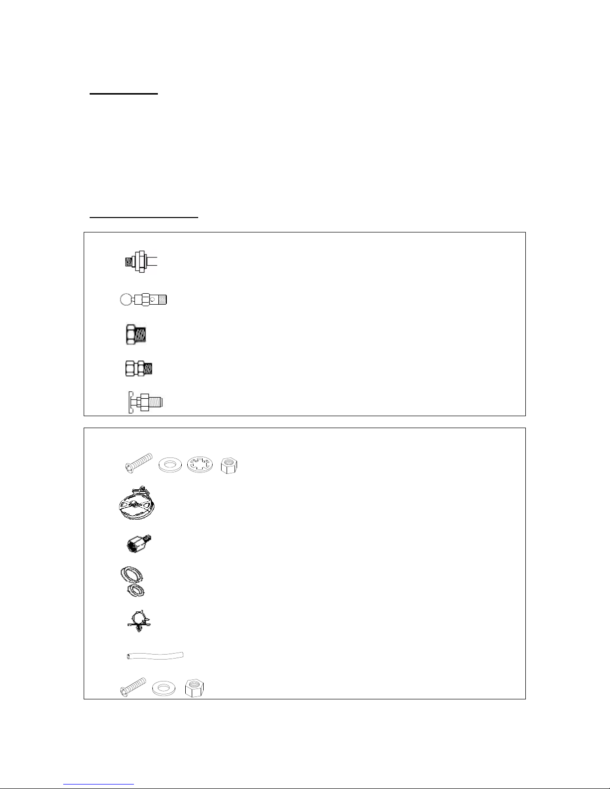
5. NOTE: For Remote Inlet A r F lter Installat on, use the prov ded plast c a r l ne and
f tt ng, as well as the prov ded a r f lter cl p.
6. Th s a r compressor comes w th a heavy duty heat res stant sta nless steel bra ded
leader hose w th ¼” f tt ngs. Th s leader hose s des gned to prolong the l fe of your
a r l ne. Do not remove th s leader hose from a r compressor.
7. IMPORTANT: The leader hose that comes w th your compressor has a bu lt- n nl ne
check valve. Do not remove nl ne check valve from leader hose.
8. Select a proper locat on to mount leader hose w th hose bracket prov ded. Avo d
locat ons where leader hose may become tangled w th w res and other hoses.
9. Connect compressor’s pos t ve lead w re to one of the leads of your pressure sw tch,
or, f you are us ng the Kle nn 6850 nstallat on k t, connect the compressor’s pos t ve
lead to p n 30 of the relay.
10. Make sure that your compressor setup s properly fused. The compressor pulls
approx mately 10 amps of power.
11. Always locate fuse as close as poss ble to power source.
12. Before connect ng to power source, check to make sure that all connect ons are made
properly.
13. Connect and test compressor system by runn ng the compressor for a short t me to
bu ld up pressure n your a r tank.
14. Once a r pressure reaches the preset cut out pressure of your pressure sw tch, the
compressor w ll shut off. Inspect all a r l ne connect ons for leaks w th soap and
water solut on. If a leak s detected, the a r l ne may not be cut squarely or pushed all
the way n. T ghten connect ons f needed.
15. Always use a “sw tched” power source that only suppl es power to your compressor
when the veh cle s runn ng.
COMPRESSOR OPERATING INSTRUCTIONS
IMPORTANT: The compressor has a max mum work ng pressure of 120 PSI and s
capable of 9% duty cycle. It s des gned for use w th a r horns, a r bags and other
accessor es that ut l ze the compressed a r stored n the tank. It s not des gned for
cont nuous use appl cat ons such as t re nflat on or a r tools. Always operate the
compressor at or below the MAXIMUM PRESSURE RATING of the compressor.
Operat on exceed ng max mum pressure rat ngs and or duty cycle w ll result n damage
to a r compressor.
1. Should your a r compressor unexpectedly shut off wh le n use; do not attempt to
restart the a r compressor. Turn off your gn t on, or f th s s not poss ble, d sconnect
the power to the compressor. After allow ng a r compressor to cool off for about 30
m nutes, you can safely resume use of the a r compressor by turn ng on the a r
compressor.
2. To prevent d scharge of your veh cle’s battery and to prov de peak performance, we
strongly recommend that you keep the veh cle’s eng ne runn ng wh le us ng the a r
compressor.
3. ONLY OPERATE THE AIR COMPRESSOR IN WELL-VENTILATED AREAS.

Compressor M inten nce & Rep irs
1. Per od cally check all electr cal and f tt ng connect ons. Clean and t ghten as needed.
2. Per od cally check all mount ng screws. T ghten as needed.
3. Replace a r f lter element per od cally. Replacement frequency depends on operat ng
frequency and operat ng env ronment. For frequent use n dusty env ronment, you
should replace a r f lter element more often.
4. Regularly clean dust and d rt from compressor.
5. Your a r compressor s equ pped w th a permanently lubr cated, ma ntenance free
motor. Never lubr cate the compressor.
6. Repa rs should be performed by Manufacturer or Manufacturer’s Author zed Serv ce
Agenc es only.
CAUTION: Never touch the a r compressor or f tt ngs connected to the a r compressor
w th bare hands dur ng or mmed ately after use. Leader hose and f tt ngs w ll become
very HOT dur ng and after use.
Compressor Inst ll tion Tips
1. Always use the remote ntake f lter opt on when poss ble. Th s w ll extend the serv ce
l fe of your compressor.
2. If no se reduct on from v brat on s des red, us ng the remote mount opt on for the
nlet f lter can reduce operat on no se by up to 25%.
3. Always mount the compressor at a po nt h gher than the nlet port of the tank. Th s
w ll keep mo sture from be ng able to seep back to the compressor.
4. When mount ng the compressor, use a pa nt pen on the rubber solators and cover the
s de to go aga nst the chass s or mount ng locat on. Then, s mply stamp the
compressor aga nst the chass s to make an mpr nt of exactly where to dr ll the
mount ng holes for the compressor.
Pressure Switch Installation
Your system comes complete w th a pressure sw tch that w ll turn on the compressor at
90 PSI, and off at 120 PSI. The pressure sw tch has a 1/8” NPT nlet at the bottom that
w ll need to be threaded nto the suppl ed hex reducer to allow t to be plumbed d rectly
to your a r tank. (Use contents of P ck ge # 1 for this inst ll tion step)
Pressure Switch Inst ll tion Tips
1. Never nstall a pressure sw tch n d rect l ne from the nlet port com ng from the
compressor. Tank pressure can be m sread by the pressure sw tch. Instead, mount the
pressure sw tch on the tank where t rece ves read ngs from deflected a r n the tank.
2. Never use a pressure sw tch that s rated beyond your compressor’s rated Max mum
Work ng Pressure (120 PSI).
3. For best performance and max mum l fe, use the Kle nn 6850 nstallat on k t to
connect your pressure sw tch to your power source.

Testing Your System
Your system nstallat on s now complete. Run the compressor to bu ld pressure n the a r
tank. When a r pressure reaches the pressure sw tch cut out pressure, the compressor w ll
shut off. Inspect all a r l ne connect ons for leaks by spray ng a soap and water solut on f
leaks are detected, re-attach hoses or apply Teflon thread tape as needed. Per od cally
check your system’s f tt ng n th s manner should your compressor turn on more often
than normal w thout frequent a r use.
Air Tank Layout
Note: Your setup may look d fferent f your tank s mounted n a pos t on other than what s
shown above. Follow these gu del nes for proper setup:
• Dra n cock should always be on the bottom
• Safety valve should always be on the top
• Pressure sw tch should be on the s de, but not d rectly oppos te the nlet from the
compressor
CAR HORN
KLEINN HORN
Table of contents
Popular Air Compressor manuals by other brands

GreenWorks Tools
GreenWorks Tools G40AC user manual

Schneider Airsystems
Schneider Airsystems UNM STB 660-10-10 Original operating manual

Sullair
Sullair TSR32 user manual

BorMann
BorMann Lite BAT5002 quick start guide

Sullair
Sullair LS20TS Operator's manual and parts list

Atlas Copco
Atlas Copco ZT55-ZT75-ZT90 Instruction book

California Air Tools
California Air Tools 10020 owner's manual

Sears
Sears Craftsman 919.153230 owner's manual

Gardner Denver
Gardner Denver EAQ99S Operating and service manual

GENTILIN
GENTILIN C660/100 instruction manual

Clas Ohlson
Clas Ohlson LC04031 manual

Vmac
Vmac UNDERHOOD 40 Series installation manual