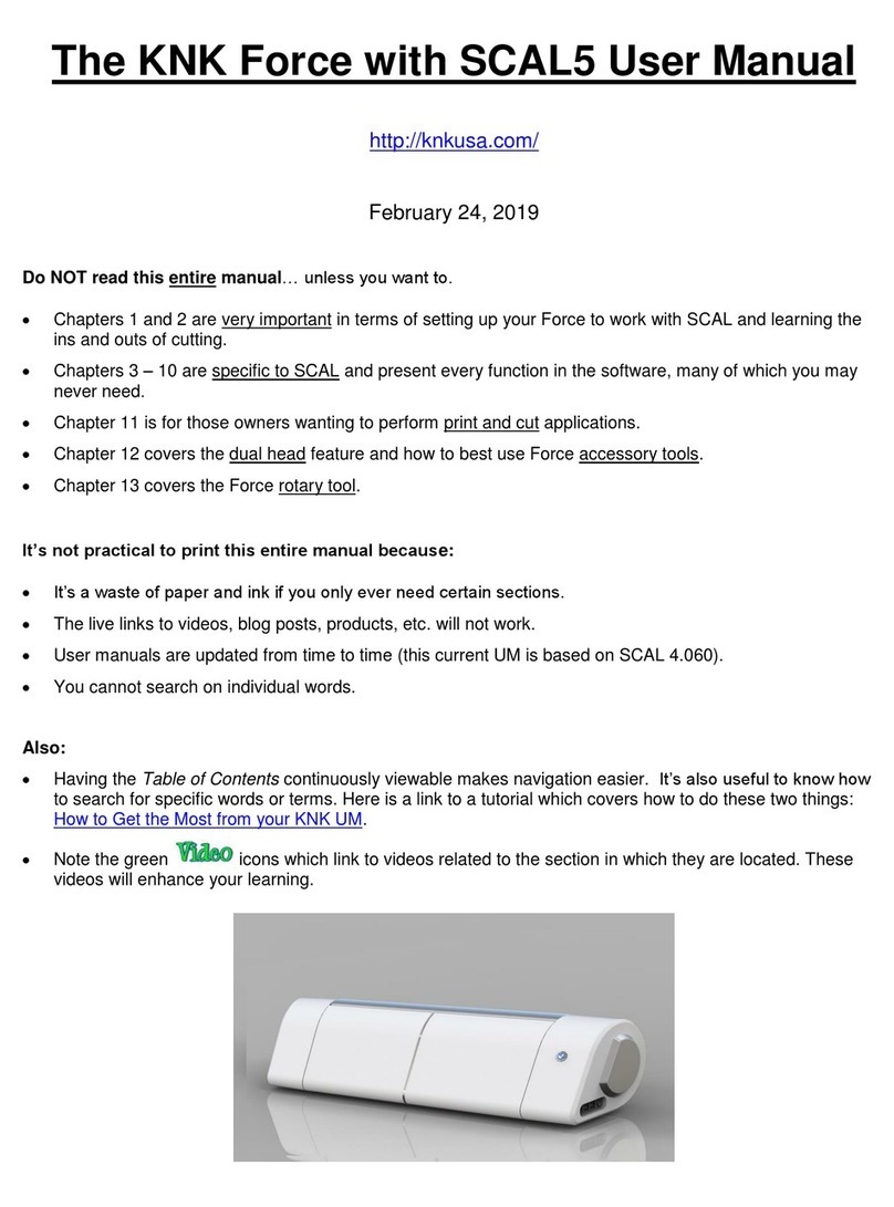
KLIC-N-KUT MAXX User manual

1
Klic-N-Kut (KNK) MAXX / Groove E User Manual1
February 2009
Thank you for choosing a Klic-N-Kut. Before using a blade in your new cutter, we suggest you read the following
sections of this user manual:
The remainder of this first page
Sections 1.1 –1.6: Important notes about the Klic-N-Kut, blades, and mat
Sections 2.1 –2.3: Installation, setup, defaults, and testing
Sections 3.1 –3.4: Brief introduction to KNK Studio
Sections 4.1 –4.3: Learning how to cut
If you run into difficulties with the operation of the cutter, turn off the power and look for a solution in this manual.
If you continue to have technical questions or issues, please contact your Klic-N-Kut supplier as soon as
possible.
You will find additional files, tutorials, videos, and support at our message board:
http://www.scrapbookdiecutter.com/support/
Please Read
Verify that you have received all contents. There is a checklist on page 4. Please notify your Klic-N-Kut
supplier immediately if anything is missing.
Remove any plastic zip ties, foam pieces or other packaging before turning on the Klic-N-Kut.
The Klic-N-Kut and other computer-connected cutters are not “plug and play” devices. Be sure to follow the
installation directions carefully and make all recommended settings before operating.
You can only install and activate the software on TWO computers. Thus carefully select which computers
you wish to use and follow the instructions carefully in this manual. In the event of a hard drive failure or the
purchase of a new computer, please contact Accugraphic at 800-268-3672 for assistance.
Use the enclosed pen and pen holder during at least the first day of operation as you become familiar with
operating the Klic-N-Kut. Place scrap paper on the mat and simply draw images rather than cut them. This
will prevent possible damage to the blade, mat, and cutting strip as you learn where images will cut and the
basic operating procedures.
DO NOT unplug the USB cable from your computer or from the cutter unless you first turn off the cutter.
Doing so can cause power fluctuations that, in turn, can damage the cutter.
Always turn off the Klic-N-Kut when not in use. Leaving the cutter turned on for extended periods of time can
possibly damage the machine.
The final printing of this user manual may not have the same color quality as intended by the author. If you
need clearer photos and diagrams, please refer to the pdf version of this user manual. Additions and
revisions to the manual will also be provided in pdf format and these can be downloaded from:
http://www.scrapbookdiecutter.com/downloads.htm
1© 2009 Accugraphic Sales, Inc., All Rights Reserved

2
Contents
1. INTRODUCTION TO THE KLIC-N-KUT................................................................................................................................................... 5
1.1 ITEMS TO NOTE (PLEASE READ!) ....................................................................................................................................................... 5
1.2 CONTENTS OF BOX............................................................................................................................................................................... 5
1.3 PARTS DIAGRAM .................................................................................................................................................................................. 6
1.4 KEYPAD PANEL .................................................................................................................................................................................... 7
1.5 BLADES AND ACCESSORIES .................................................................................................................................................................. 9
Testing Pen Holder:..................................................................................................................................................................................................... 9
Blades Included With Klic-N-Kut Purchase:................................................................................................................................................................ 9
Blade Installation:........................................................................................................................................................................................................ 9
Setting the Blade Length:.......................................................................................................................................................................................... 10
Other Blades and Accessories:................................................................................................................................................................................. 10
1.6 MAT (CARRIER SHEET)....................................................................................................................................................................... 11
1.7 ATTACHING THE KNK BOLT-ON TABLES.............................................................................................................................................. 11
2. INSTALLATION AND SETUP ................................................................................................................................................................ 13
2.1 INSTALLATION OF THE KNK AND SOFTWARE......................................................................................................................................... 13
Port Setup: (communication between your computer and the cutter)...................................................................................................................... 14
2.2 IMPORTANT DEFAULTS TO CHECK........................................................................................................................................................ 14
2.3 QUICK DRAW TESTING (TO VERIFY COMMUNICATION)............................................................................................................................ 16
2.4 CALIBRATING THE KLIC-N-KUT ............................................................................................................................................................ 17
3. KNK STUDIO BASICS ........................................................................................................................................................................... 19
3.1 MAIN KNK STUDIO SCREEN................................................................................................................................................................ 19
3.2 TOOLS TOOLBAR (WHERE THE GOOD STUFF RESIDES!) ......................................................................................................................... 20
3.3 MANAGING FILES................................................................................................................................................................................ 20
Opening a New Document (Sign Blank Setup)......................................................................................................................................................... 20
Opening an Existing KNK File................................................................................................................................................................................... 21
Saving and Exporting ................................................................................................................................................................................................ 22
3.4 MANIPULATING IMAGES....................................................................................................................................................................... 22
Zooming .................................................................................................................................................................................................................... 22
Selecting.................................................................................................................................................................................................................... 22
Deleting ..................................................................................................................................................................................................................... 23
Moving....................................................................................................................................................................................................................... 23
Copying ..................................................................................................................................................................................................................... 23
Resizing and Stretching ............................................................................................................................................................................................ 24
Rotating ..................................................................................................................................................................................................................... 24
Mirroring and Flipping................................................................................................................................................................................................ 24
Slanting ..................................................................................................................................................................................................................... 24
Locking ...................................................................................................................................................................................................................... 25
Re-Coloring ............................................................................................................................................................................................................... 25
Arranging................................................................................................................................................................................................................... 25
Grouping.................................................................................................................................................................................................................... 26
Undo Navigator ......................................................................................................................................................................................................... 26
3.5 FILLING A PAGE WITH THE SAME IMAGE ............................................................................................................................................... 26
Method A: Array ........................................................................................................................................................................................................ 26
Method B: Repeats.................................................................................................................................................................................................... 26
4. CUTTING ................................................................................................................................................................................................ 27
4.1 CUTTING DEFAULTS............................................................................................................................................................................ 27
4.2 SETTINGS FOR YOUR MATERIALS AND IMAGES ..................................................................................................................................... 29
Blade ......................................................................................................................................................................................................................... 29
Speed ........................................................................................................................................................................................................................ 29
Pressure .................................................................................................................................................................................................................... 29
4.3 CUTTING PROCEDURE ........................................................................................................................................................................ 30
Important Checklist Before You Cut!......................................................................................................................................................................... 30
Setting the Origin *** VERY IMPORTANT *** .......................................................................................................................................................... 30
Test Cut..................................................................................................................................................................................................................... 30
Pausing and Aborting a Cut ...................................................................................................................................................................................... 31
Selecting the Image(s) to Cut.................................................................................................................................................................................... 31
Cutting Procedure ..................................................................................................................................................................................................... 31
4.4 CUTTING BY COLOR............................................................................................................................................................................ 33
Method A: Sort and Cut All Colors ............................................................................................................................................................................ 33

3
Method B: Filter By Color .......................................................................................................................................................................................... 33
Method C: Filtering Colors in the Sign Blank ............................................................................................................................................................ 33
4.5 USING THE POUNCE FEATURE TO CUT DASHED LINES.......................................................................................................................... 33
Cut and Pounce in One Step .................................................................................................................................................................................... 33
Pounce First and Then Cut ....................................................................................................................................................................................... 34
4.6 CONTROLLING THE ORDER,START,AND DIRECTION OF CUTS............................................................................................................... 35
Sequence .................................................................................................................................................................................................................. 35
Sort............................................................................................................................................................................................................................ 35
Object Start Point and Path Direction ....................................................................................................................................................................... 35
4.7 PRINT AND CUT .................................................................................................................................................................................. 35
Calibrating the Laser Light (MAXX models only) ...................................................................................................................................................... 35
Calibrating the Alignment Pin (Groove E Model Only).............................................................................................................................................. 37
Performing a Print and Cut........................................................................................................................................................................................ 38
Alternative Reverse Cut and Print Method................................................................................................................................................................ 42
4.8 CONTOUR CUTTING ............................................................................................................................................................................ 42
5. WORKING WITH TEXT .......................................................................................................................................................................... 43
5.1 INSTALLING/UNINSTALLING FONTS....................................................................................................................................................... 43
5.2 TEXT BASICS...................................................................................................................................................................................... 43
5.3 COPYING TEXT STYLE FROM ONE TITLE TO ANOTHER .......................................................................................................................... 44
5.4 CONNECTED LETTER TITLE WITH A MAT............................................................................................................................................... 44
5.5 OUTLINE AND INLINE ........................................................................................................................................................................... 45
5.6 FITTING TEXT TO CURVES................................................................................................................................................................... 46
5.7 FITTING TEXT TO PATHS ..................................................................................................................................................................... 47
5.8 OTHER TEXT TRANSFORMATIONS........................................................................................................................................................ 47
5.9 INCORPORATING DINGBAT IMAGES IN A TITLE....................................................................................................................................... 48
5.10 WELDING TEXT TO FRAMES .............................................................................................................................................................. 48
5.11 BADGES........................................................................................................................................................................................... 49
5.12 STENCILING LETTERS ....................................................................................................................................................................... 51
5.13 THE FONT DETECTIVE ...................................................................................................................................................................... 52
6. TRACING ................................................................................................................................................................................................ 53
6.1 AUTO-TRACING USING THE PREPARE TO VECTORIZE WIZARD............................................................................................................... 53
6.2 CENTER LINE TRACING ....................................................................................................................................................................... 58
6.3 MANUAL TRACING .............................................................................................................................................................................. 59
Importing the Image to Trace .................................................................................................................................................................................... 59
Straight Line Tracing ................................................................................................................................................................................................. 59
Curved Line Tracing.................................................................................................................................................................................................. 61
Combined Straight Line and Curved Tracing ............................................................................................................................................................ 62
7. EDITING.................................................................................................................................................................................................. 63
7.1 BREAKING PATHS /MAKING PATHS...................................................................................................................................................... 63
7.2 BASIC NODE EDITING.......................................................................................................................................................................... 63
7.3 REDUCING NODES.............................................................................................................................................................................. 64
7.4 USING SEGMENT EDIT TO SMOOTH CURVED SECTIONS ........................................................................................................................ 65
7.5 DELETE TOOLS IN POLYARC EDITING................................................................................................................................................... 66
7.6 USING THE GINSU KNIFE TOOLS.......................................................................................................................................................... 67
7.7 ADDITIONAL EDITING TOOLS................................................................................................................................................................ 68
Connect Path............................................................................................................................................................................................................. 68
Close Graphics.......................................................................................................................................................................................................... 68
Converting a Closed Path to a Perfect Circle............................................................................................................................................................ 68
7.8 MAKING PATHS OR GROUPING ............................................................................................................................................................ 69
7.9 EXAMPLE OF EDITING A VECTORIZED IMAGE......................................................................................................................................... 69
8. DESIGNING ............................................................................................................................................................................................ 71
8.1 ADDING GUIDELINES TO THE SIGN BLANK ............................................................................................................................................ 71
8.2 DRAWING AND MODIFYING BASIC SHAPES ........................................................................................................................................... 71
Modifying a Rectangle............................................................................................................................................................................................... 72
Modifying a Polygon.................................................................................................................................................................................................. 72
Modifying a Star ........................................................................................................................................................................................................ 72
Modifying a Fan......................................................................................................................................................................................................... 72
Modifying a Monument.............................................................................................................................................................................................. 72
8.3 THE THREE WELDING TOOLS .............................................................................................................................................................. 73

4
Basic Weld ................................................................................................................................................................................................................ 73
AND Weld.................................................................................................................................................................................................................. 73
XOR Weld ................................................................................................................................................................................................................. 73
8.4 STENCIL TOOL ................................................................................................................................................................................... 73
8.5 CLIPPING ........................................................................................................................................................................................... 74
8.6 ARC EDIT........................................................................................................................................................................................... 74
8.7 TRANSFORM FUNCTIONS..................................................................................................................................................................... 75
Round Corner............................................................................................................................................................................................................ 75
Fillet Round Corner ................................................................................................................................................................................................... 75
Metamorphosis.......................................................................................................................................................................................................... 76
Fit Object to Path....................................................................................................................................................................................................... 76
Shadow ..................................................................................................................................................................................................................... 76
Render to Bitmap ...................................................................................................................................................................................................... 76
8.8 POLYARC EDITING .............................................................................................................................................................................. 76
8.9 DECORATIVE BORDER ........................................................................................................................................................................ 77
8.10 ARRAY............................................................................................................................................................................................. 77
8.11 ANOTHER KIND OF STENCILING ......................................................................................................................................................... 78
8.12 CREATING LATTICE DESIGNS............................................................................................................................................................. 78
8.13 FREEHAND DRAWING........................................................................................................................................................................ 79
8.14 ENHANCING YOUR DESIGN FILES ...................................................................................................................................................... 79
9. SPECIAL TOPICS .................................................................................................................................................................................. 81
9.1 CUTTING CHIPBOARD ......................................................................................................................................................................... 81
9.2 CUTTING VINYL .................................................................................................................................................................................. 81
Weed ......................................................................................................................................................................................................................... 83
Power Weed.............................................................................................................................................................................................................. 83
9.3 CUTTING FABRIC AND FELT ................................................................................................................................................................. 83
9.4 USING BANNER FILL FOR EMBOSSING,ENGRAVING,OR DRAWING IN COLOR.......................................................................................... 83
9.5 USING THE ENGRAVING/EMBOSSING DROP-IN TOOL............................................................................................................................. 85
9.6 USING THE PUNCH TOOL .................................................................................................................................................................... 85
9.7 USING INSTANT REPLAY AND THE STORAGE BIN................................................................................................................................... 86
9.8 BLOCK NESTING................................................................................................................................................................................. 86
9.9 FILE CONVERSIONS ............................................................................................................................................................................ 87
Converting from .GSD to .KNK ................................................................................................................................................................................. 87
Converting from .KNK to .GSD ................................................................................................................................................................................. 88
Converting from Inkscape .SVG to .KNK and Vice-Versa ........................................................................................................................................ 89
Converting from .KNK to .WPC and Vice-Versa ....................................................................................................................................................... 89
Converting from .AI to .KNK and Vice Versa ............................................................................................................................................................ 89
Converting from .PDF to .KNK and Vice Versa......................................................................................................................................................... 89
Converting to a Raster Image: .................................................................................................................................................................................. 91
9.10 FEATURES FOR PROFESSIONALS....................................................................................................................................................... 91
Templates.................................................................................................................................................................................................................. 91
Job Tracking.............................................................................................................................................................................................................. 91
Estimating Cut Distance............................................................................................................................................................................................ 92
Job/Cost Notes.......................................................................................................................................................................................................... 92
Insert New Object...................................................................................................................................................................................................... 92
Notepad, Calculator, Time Sign ................................................................................................................................................................................ 92
Page Control ............................................................................................................................................................................................................. 92
APPENDIX A KEY BOARD SHORTCUTS ............................................................................................................................................... 93
APPENDIX B TERMINOLOGY.................................................................................................................................................................. 96
APPENDIX C TROUBLESHOOTING...................................................................................................................................................... 100
APPENDIX D SETTINGS FOR AUTO-TRACING ................................................................................................................................... 104
INDEX ....................................................................................................................................................................................................... 105

5
1. Introduction to the Klic-N-Kut
1.1 Items to Note (PLEASE READ!)
Power Supply: The Klic-N-Kut’s power supply is 90V-230V. If your supply is different from this, please use
a power converter. Remove the power cable if the cutter will not be in operation for a significant length of
time.
Connecting to Your Computer: You have the option of connecting via the RS232 serial port OR via the
USB port. Your shipment contains both a USB cable and a serial cable, although your computer may not
have a serial port installed.
Blades: The blades used by cutters are extremely fragile. Do not drop or even bump the blade onto any
hard surface as they can chip easily. When not in use, retract the blade into the blade holder or remove
and cover the sharp end with the soft plastic cap.
Warranty: The one year warranty covers Manufacturer’s Defect only and does not include normal wear
and tear. If warranty work is required, the owner is responsible for shipping costs to and from Accugraphic
Sales. If a Klic-N-Kut is damaged during shipment, then your dealer should be notified as soon as
possible. If damages are reported later than three weeks after delivery, then it will be the responsibility of
the owner to ship the damaged KNK back to Accugraphic for repair.
Transporting: When transporting the cutter, move the pinch wheel levers into the upward position.
Remove the accessories from the tool tray and place in a separate bag. We also recommend retaining
the original box with the Styrofoam inserts in case you ever need to ship your Klic-N-Kut.
Additionally:
oDO NOT touch or jam the plotter’s track while it is operating. If the cutter is damaged, it is the
owner’s responsibility.
oDO NOT shake the cutter while it is operating.
oDO NOT cut any materials that have staples or other embellishments attached.
oDO NOT touch the cutter with a magnet.
oDO NOT allow small items to fall into the cutter.
oTURN OFF the cutter when not in use.
1.2 Contents of Box
Please verify that you have received the following items. If anything is missing, please contact your Klic-N-Kut
supplier as soon as possible.
Klic-N-Kut MAXX or Groove E Cutter
Cutting Mat
Klic-N-Kut Studio Installation CD
Krylon Spray
1100 Font and 3900 Clip-art CD
User Manual
Designers' Collection 1 CD
Ruler
Blade Holder
Power Cord
Two blades (red cap and blue cap)
Serial and USB Cables
Laser or Alignment Pin Calibration Sheet
Bolt-on Tables
Testing Pen Holder with 2 pen inserts
Alignment Pin (Groove E model only)

6
1.3 Parts Diagram
Front
Left Side Right Side
Back
Keypad Panel
Blade Carriage
Blade Holder Seat
Bolt-On Front Table
Pinch Wheel:
Total of 3 (2 on Groove E)
Pinch Wheel
Positioning Label:
Total of 4 (5 on 24”)
Cutting Strip
Grit Shaft (beneath
Pinch Wheels):
Total of 4 (5 on 24”)
Power Port
On/Off Switch
USB Port
RS232 Serial
Port
Pinch Wheel
Lever:
Total of 3 (2
on Groove E)
Bolt-On Back
Table
Carrier Sheet
(Mat)

7
1.4 Keypad Panel
Online Mode Display
v = cutting velocity, mm/sec
f = cutting force (scaled from 1 to 160)
1. LCD Display
2. Test: Cuts a small test shape when cutter is in
Offline mode
3. Online / Offline Toggle
4. Menu
5. Repeat: repeats last cut when cutter is in Offline
mode
6. Pause: Will pause cutter in the middle of a cut; press
again to resume cutting
1
2
4
3
5
6
7
8
9
10
11
Increase/Decrease
Velocity (Speed)
Increase/Decrease
Cutting Force
(Pressure)
Move the mat
forward or towards
the back
Move the carriage
left or right
Offline Mode Display
x = forward/back distance from origin
y = left/right distance from origin
Step 1: Turn on the KNK.
A welcome message will
flash for a few seconds when
cutter is first turned on. Then
the cutter will come to rest in
the Online Mode.
Experiment with “+” and “-“
buttons, as shown.
7. Offline Mode: moves carriage to the left;
Online Mode: increases cutting force
8. Offline Mode: moves mat to the back; Online
Mode: increases cutting speed
9. Offline Mode: moves carriage to the right;
Online Mode: decreases cutting force
10. Sets the Origin
11. Offline Mode: moves mat forward;
Online Mode: decreases cutting speed
Step 2: Press the Online
button.
This will change to Offline
mode. Experiment with “+”,
“-“, TEST, and Origin
buttons, as shown.
Press the Origin button to set the
origin. Note the cutter will remain in
the Offline Mode.
Press the Test button for a
small shape to cut at the
origin. Note the cutter will
then be in Online Mode.
Go through the
various modes below
to experiment with
the settings and
understand each
mode.

8
Laser Mode Display (MAXX models only)
Setting Display
Us = Traverse speed (movement of carriage
when head is up)
Br = Baud rate (USB: 57600, Serial: 9600)
Set Per Display
Xp = Calibration of X scale
Yp = Calibration of Y scale
Step 3: In Offline Mode, press
the Menu button.
The Laser display will show
and the laser can be activated.
Press the Origin button to
turn the laser light on. You
will see a red light appear
below blade carriage. Also,
the cutter will change to
Online mode. To turn off the
laser, repeat Steps 2 and 3
and then press the Origin
button again.
Step 4: In Online Mode, press
the Menu button.
Experiment with the “+” and “-“
buttons for the Traverse
Velocity. Change the Baud
Rate based on the connection
you are using.
Increases/Decreases
Traverse Velocity
(Speed)
Increases/Decreases
Baud Rate: USB:
57600
Serial: 9600
Step 5: In Online Mode, press
the Menu button twice.
Press again to turn off the
Menu function.
Do not change these values.
Instead, it is recommended
that calibration of the KNK
be done from within the
KNK Studio program. Refer
to Section 2.4.
Pause Display
v = cutting velocity, mm/sec
f = cutting force (scaled from 1 to 160)
Press the Pause button during
the cut and the cutter will
immediate stop cutting.
As shown above, use the “+”
and “-“ buttons to change the
cutting velocity or cutting force
and press Pause again to
resume the cut.
…OR…
Turn off the cutter to abort the
cut.
At the end of a cut, the Repeat
button can be pressed to
activate the same cut again.

9
1.5 Blades and Accessories
Testing Pen Holder:
The testing pen should be used until you are comfortable with the operation of the Klic-N-Kut and know, with
certainty, where images will cut. To assemble this testing pen, remove the top cap, slip the spring over the
top half of the pen insert and then drop the pen insert into the bottom half of the pen holder. Slide the cap
over the pen insert, allowing the pen insert to fit through the hole at the top of the cap. Screw into place.
Blades Included With Klic-N-Kut Purchase:
There are two kinds of blades included: The red capped blades are suited for cutting thinner materials such
as paper, vellum, vinyl, and thin cardstock. The Sliver 2 blue capped blades are much longer blades and
are well-suited for cutting thicker materials, such as textured cardstock, chipboard and craft foam.
Additionally, there are other tools sold separately that can fit into the blade holder, such as the fabric blade,
the engraving/embossing tip, and the punch tool (see below). Note that it’s VERY IMPORTANT to insert
the correct end into the blade holder to avoid permanently damaging the blade holder. All of the “non-
blade” ends are inserted with the “useful/sharp end” protruding through the bottom.
Blade Installation:
The blade must be carefully inserted into the blade holder. Do this over a soft surface (e.g. over a hand
towel). It’s important to protect the fragile blade! To install, follow the numbered steps as shown:
In Step 5, hold the material you are cutting up next to the blade and turn the silver gridded part to adjust the
amount of blade protruding. You will want to only see enough blade, as needed, to cut through the
thickness of the material to be cut. This is less than you probably think! So be on the conservative side first
and you can always extend the blade, as needed. More information is covered in the following subsection:
Setting the Blade Length.
If you received a second silver blade holder with your purchase, then use the following instructions for
inserting a blade and adjusting the blade exposure:
3. Turn counter-clockwise to
retract the blade.
4. Turn counterclockwise to
move towards the top.
5. Turn clockwise to set blade length
to match the thickness of the material
being cut.
6. Turn clockwise until
locked in place.
1. Push in and hold so
that a blade can be
inserted OR removed.
2. Gently insert non-
sharp end into
holder. An internal
magnet will pull the
blade inwards.

10
Setting the Blade Length
Getting the blade length set correctly for the cut is just as important as setting the cutting pressure. If you
have too little blade exposed, then it cannot cut all the way through the material. If you have the blade too
long, then the tip of the blade will be cutting into the mat which will dull the blade sooner, damage the mat,
and typically result in worse cutting, rather than better:
Perfect Length Too Long: cuts into mat Too Short: will not completely cut
When setting the blade length, hold up the blade holder next to the material so that you can more accurately
set the length to match the thickness of the material. If you have a difficult time seeing the tiny blade, try
using your finger to feel for the tip of the blade to be just a tiny bit longer than the material’s thickness. One
method used by many owners is to fold the material over onto itself and then, with the blade holder in your
hand, manually cut a short line. The cut should penetrate the top layer but not cut into the second layer.
Also develop the habit of using the Test button on the KNK to verify that you not only get a clean test cut,
but when you lift the waste and the test cut from the mat, you cannot see cut lines in the mat. It is okay to
see very faint markings, suggesting the tip of the blade is just barely grazing the adhesive on the mat. But
again, if you see cut lines, then shorten the blade slightly and test cut again. For many new owners, this
may seem like a difficult task, but it only takes a little practice and then setting the blade length will seem
quite easy to do.
It’s also important to have the blade holder mounted so that the tip of the blade is slightly above the cutting
material. This is to prevent the blade from dragging across the material when moving from one cutting path
to the next and to give the blade more downward impact when dropping to cut into the material. More
information about cutting is covered in Chapter 4 and it is strongly recommended that you read Sections 4.2
and 4.3 before attempting to cut.
Other Blades and Accessories:
The following items can be purchased at http://www.scrapbookdiecutter.com for use in the Klic-N-Kut MAXX and
Groove E machines:
Silver Blade Holder: Previously sold with the Klic-N-Kuts, this blade holder uses the same blades and
accessories and fits into the new MAXX and Groove E machines. Note that if either the Sliver 1 or Fabric
Blade is to be used, a replacement end cap is needed.
Fabric Blade: Cut at a blunter angle, this blade is well suited for cutting fabric.
Embossing/Engraving Tip: This alternative to a blade is used for engraving on metal or hard plastics (such as
acrylic) or embossing on vellum and cardstock. It comes with a felt strip which can be placed over the white
cutting strip and materials can be engraved and embossed without using a mat.
1. Unscrew cap and
set aside.
3. Replace cap and screw onto main section
only until blade exposure matches the
thickness of the material being cut.
2. Gently insert non-sharp end into holder. An
internal magnet will pull the blade inwards.
Mat
Material

11
Punch Tool: This alternative to a blade is used to punch small holes for paper embroidery or Dutch paper
crafting. Place one of the accompanying rubber strips over the white cutting strip and materials can be
punched without using a mat.
Multi-Use Tool: While the Maxx and Groove E cutters have an adjustable blade holder seat, some pens or
embossing styluses may not fit properly. This is especially true if the bottom of the pen or stylus has a long
tapering to the tip. The Multi-Use tool will fit pens and other tools up to ~11/32” or ~ 9 mm in diameter.
Light Pressure Wheel Assembly: Similar to the existing pinch wheels, this light pressure version is an add-on
assembly used to control bowing of certain materials during cutting.
KNK MAXX 24” x 30” Mat: This extra large mat is for use in the 24” KNK MAXX machine.
1.6 Mat (Carrier Sheet)
Always use the mat to hold the material to be cut unless the material has its own protective backing.
If your mat arrived with a can of Krylon Easy Tack, carefully follow the directions on the can. Shake the can
well and place your mat on newspaper in a well-ventilated area such as a patio or inside a garage. Never
spray near other objects! Spray the top printed side back and forth vertically and horizontally, making sure
to cover the surface thoroughly, but do not soak. Allow about 30 minutes to dry.
While Krylon Easy Tack has proven to be an excellent mat adhesive for cutting paper and cardstock,
alternative adhesives may be used in place of the Krylon. If you are cutting thicker materials, such as
stiffened felt or styrene, then you may want to experiment with stronger adhesives or use painter’s tape to
secure the material to the mat. If you are cutting thin paper, then you may want to experiment with lighter
adhesives.
Use a plastic scraper (an old credit card will suffice) to scrape off any random material pieces remaining on
the mat after a cut. For finer particles of paper or lint, you can use a lint roller. Tear off a sheet and then
press down and pull up across the surface of the mat to clean in sections.
When mats begin to lose their stickiness, they can be washed. Use a mild dishwashing detergent, warm
water, and a soft brush to thoroughly clean the surface. Then allow to thoroughly dry. Normally, the mat will
regain its original stickiness. But if not, spray again with Krylon.
If the newly-sprayed mat is too sticky, causing difficulty in removing paper pieces, dab an old, but clean T-
Shirt over the surface of the mat until stickiness is more appropriate for your material.
Avoid direct contact between the pinch wheels and the mat as the rubber on the wheels will tend to pick up
the adhesive and then later stick to the paper or cardstock you are cutting. If this happens, these rubber
wheels may be cleaned with isopropyl alcohol or Un-Du. Move the wheel away from a grit shaft, apply the
cleaner to a clean rag or paper towel, and rub the entire wheel until free of adhesive.
One alternative to spraying the entire mat with the adhesive is to mask off all areas except for those you
will be using and spraying only those areas. For example, if you only cut from 12”x 12”cardstock, then
only apply adhesive to that portion of the mat. This also economizes your usage of adhesive.
Alternatively, silicon spray or silicon grease can be applied to the rubber wheels and then the adhesive
from the mat will not stick to the rubber. Do not spray the wheels directly; instead spray a clean rag or a
paper towel and then apply the wet paper towel to the wheels, or use a cotton swab to apply the silicon to
the wheels.
1.7 Attaching the KNK Bolt-On Tables
The installation of the front and rear tables on your KNK is best done with two people. Each box contains 2
identical tables (front and rear) and 8 screws.

12
First, lay a soft towel down. Next, gently turn your
KNK upside down to expose the bottom panel.
Unscrew the screws along one side of the bottom
panel.
Next, slip one of the tables into place and put
the bottom screws back in. Once the screws
are tightened, turn the KNK back over, where
the cutter is facing up.
Insert 4 of the 8 screws that were packaged
inside the box with the tables. Be sure to keep
the four screws relatively loose until all four have
been inserted. Then tighten down but not too tight
or you will risk stripping the threads.
Repeat this for the other side of the KNK.

13
2. Installation and Setup
2.1 Installation of the KNK and Software
The Klic-N-Kut comes with three CD’s: a KNK Studio software installation CD, a Clipart and Fonts CD (with
3900 .knk files and 1100 fonts) and a Designs and Images CD (with 174 .knk files and a short video on using
the Clipart Viewer). This third CD does not require installation; instead you can access the files via My Computer
or the Clipart Viewer in KNK Studio.
(1) Close all programs not needed and insert the Klic-N-Kut Studio installation CD into a CD Rom drive.
Follow the menu directions to begin installing the program.
(2) When asked to install your Windows fonts, do so. After these are installed, you will be prompted to install
the Clipart and Fonts CD. This is optional and these fonts and clipart can be installed at a later time, if
desired. Refer to Sections 5.1 and 3.3 and the video on the Designs and Images CD.
(3) The program will notify you that the driver will be installed. If you are using XP, you will probably receive
pop-up windows in which you will need to click on Continue Anyway. In Vista you may immediately see
an option to click on Finish. Wait a moment to allow the driver to finish installing. Then click on Finish.
Restart Windows. If you are using a Windows emulator on a Mac, then restart the computer.
(4) After you have successfully installed the software, a KNK Studio icon should now be present on your
desktop. Launch the software. You will be asked if you want to register the demo version of KNK Studio.
Click on Yes. Note that you need to be connected to the Internet for registration.
(5) A registration window will open. Locate your Software Activation Pin on the inside of the box which
contained the software, cables, etc. Enter this number into the screen, along with the other registration
information, and click on Activate Software. The program will then connect to the Internet and update the
software installation with a pair of license files for use on that computer. You will receive a message saying
that the license files updated successfully. You will also receive an email from CADLink verifying the
activation and providing a link to download your license files, if ever needed. Note that if you activate on a
second computer, the license files will be different from those generated on your first computer, so avoid
mixing them up. It’s a good idea to back up these files. They are called Products.lcf and Products.ini. Both
are present in your c:\Klic-N-Kut Studio Maxx folder. If KNK Studio still appears to be in demo mode, then
copy/paste those two files into your c:\Klic-N-Kut Studio Maxx folder, overwriting the current versions.
(6) If you choose not to register, then you will only be able to cut a total of 10 times and you will not be able to
copy/paste or duplicate images. The countdown for the number of cuts and access to the registration
window can be found under Help>Register.
(7) Place the Klic-N-Kut on a sturdy horizontal surface. If you have not yet done so, attach the bolt-on tables
to the cutter (Refer to the instructions in Section 1.7 Attaching the KNK Bolt-On Tables.) If you are not
going to use the tables, then be sure to allow enough free room in both the front and the back for the mat
to extend during cutting.
(8) Connect the power cord to the left side of the cutter and plug into a wall outlet or power strip. Turn on the
power using the power switch on the left side. The yellow LED display should come on and the cutter will
initialize (carriage will move to the far right side of the cutter). Note that the display indicates the current
pressure and speed settings. Refer to Section 1.4 Keypad Panel to learn the various display modes and
how to make changes.
(9) A. USB Connection: Turn off the cutter and connect the USB cable to the right side of the cutter and into
an available USB port on your computer. Turn on the cutter. If your computer is running Windows XP or
Windows Vista, the hardware manager will identify the USB connection. If the Hardware Installation
window pops open, proceed and accept all defaults. On the Control Panel, press the Menu button and
verify that the Baud Rate is set to 57600. Refer to Section 1.4, Step 3.
B. Serial Connection: Turn off the cutter and connect the RS232 cord to the right side of the cutter and
into the serial port on your computer. Turn on your cutter. If your computer is running Windows XP or
Windows Vista, the hardware manager will identify the serial cable connection. On the Control Panel, press
the Menu button and change the Baud Rate to 9600. Refer to Section 1.4, Step 3.

14
Port Setup: (communication between your computer and the cutter)
(1) To verify the COM port, select File>Control Panel and switch to Classic View, if necessary.
(2) In Windows Vista, click on Device Manager. In Windows XP or earlier, select System from the list,
then select the Hardware tab, and click on Device Manager.
(3) Locate Ports and open. If using USB, look for a USB labeled (COMX) where X is the number you
need to match as your port location. If using a direct serial connection, look for Communications Port
(COMY) where Y is the number you need to match as your port location. Your wording may vary
slightly from what’s shown in this diagram:
(4) If you do not see a Ports subfolder first try a different USB port and check your USB cable, then
contact your KNK Supplier for assistance or visit our message board at the link on Page 1.
(5) Go to Cut>Plotting Defaults and click on Setup. Click on the Port tab. Verify that Direct to Port is
checked.
(6) Under Port Location, select the COM Port determined in Step (3). If you are using a serial connection,
you will also need to check the Edit box and change the Baud rate to 9600. Also refer to Section 1.4
Step 4, where it shows how to change the Baud rate on the Keypad Panel, as well. Changes in both
locations are necessary for the serial connection to work.
(7) Click on Apply and then OK. It is recommended that the same USB port on your computer always be
used. Otherwise you will need to change the COM port assignment as you change ports.
2.2 Important Defaults to Check
There are dozens of settings in KNK Studio which are either critical to getting the cutting results you want or are
useful for customizing the software to meet your needs. The following are some of the very basic settings you’ll
want to check right away. To fully understand how other settings will affect cutting, please refer to Chapter 3.
Units : Go to Options>Klic-N-Kut Setup>General Preferences and choose inches or mm.
Look for COM port
assignment under Ports.
On the left, COM 7 was
assigned to the USB
connection and, on the
right, COM 8 was
assigned to the Serial
Connection.
Select assigned
COM port from
drop-down menu.
Confirm other
default settings.
USB Connection
Serial Connection
Select assigned
COM port from
drop-down menu.
Change Baud
rate to 9600 and
confirm other
default settings.
Check Edit.
USB Connection
Serial Connection

15
Toolbars: Go to View>Toolbars –there are four in total and it’s useful to have them all showing (click on
one to turn it on/off) until you determine which features you find most useful. You can then create a custom
toolbar with just those you need most often. (View>Toolbars>Customize)
Palettes: Go to View>Palettes –there are three in total. The important ones are the Shop Palette (which
shows all available colors for your vector images) and the Job Palette (which tracks all colors that have
been used in the current file). To activate a palette, click on the name to check it.
Show Sign Blank: Go to View>Show Sign Blank –makes document boundaries visible.
Tool: Go to Cut>Plotting Defaults and, under Tool, select Drag Knife. Note that you must click on Apply
to lock in a change in this window. Then you can click on Close.
Axis Swap: Go to Cut>Plotting Defaults - checking Axis Swap will cut your images left to right, as you
see them on the screen, similar to a portrait orientation. Un-checking Axis Swap will rotate images and cut
them front to back on the cutter, similar to a landscape orientation. Refer to Section 4.1 for a clearer
understanding of where images will cut. Again, click on Apply if you make a change in this window.
Page versus Sign Blank: Go to Cut>Plotting Defaults –checking Page mode will cause images to be
moved to the origin to be cut. Checking Sign Blank will cut the images in the same location as shown in
the Sign Blank. Again, refer to Section 4.1 for a clearer understanding of where images will cut and click on
Apply if you make a change in this window.
Machine Limits: Go to Cut>Plotting Defaults, click on Setup. These are the maximum and minimum
length and width for cutting. Set the Length to at least 15” or longer. If you plan to cut vinyl, then you may
wish to make it as long as 48”, although there is no limit. Set the Width to 15” or 24” or whatever width
matches your cutter’s limit. If working in metric, enter the appropriate equivalents in mm.
Multiple Instance: Go to Options>Multiple Instance - allows more than one file to be opened at a time.
Automatic Save: Go to Options>Automatic Save –creates backup files while you are working.
Show Grid: Go to View> Show Grid –turn on/off the grid. There is also an icon for this on the Workspace
toolbar.
Grid Size: Go to Options>Klic-N-Kut Setup>General Preferences –sets distance between grid lines.
Duplicates: Go to Options>Klic-N-Kut Setup>General Preferences - When you use Edit>Duplicate to
copy an image, this is the offset from the original. If you want the duplicate to be directly on top of the
original, enter 0 for both values. Usually, you will want the image offset by some amount so that it’s
apparent you have a duplicate available.
Show Fill: Go to View>Show Fill –turns on/off the fill. With Show Fill turned on, closed images will be
filled with the color you select from the Shop Palette on the bottom of the screen. Open images will appear
with dashed lines. There is also an icon for this on the Workspace toolbar or you can use Alt-S.
Overcut and Trailing Blade –these settings compensate for the angle of the blade. Go to Cut>Tool
Options. The Overcut setting ensures that paths are fully closed. The Trailing Blade setting enhances
the sharpness of corners. Depending on the blade you are using and the intricacy of the cut, these values
will need to be altered for the Drag Knife only. The following table shows recommended values for these
parameters:
In this same Cut>Tool Options window, the values above can be stored under Material. Enter values for
Overcut and Trailing Blade, and then click on the Add Material button. Enter a name for the listing, such
as “Red Capped Blade” or “Large Shapes” and then click on OK. This menu list is then available in the
Layout>Blank Size window where you also select the dimensions for your Sign Blank.
Enter more values based on
future KNK blades or your own
experiences with certain designs
or materials.

16
2.3 Quick Draw Testing (to verify communication)
New owners tend to be VERY eager to try out their Klic-N-Kut. It’s also important to test your cutter to ensure
that data is being sent properly from your computer to the cutter. The following steps will allow you to do some
testing with the pen tool. But note that the following steps are for DRAWING, not cutting. Before inserting
the blade tool into the Klic-N-Kut, please read the following Sections: 1.4 Keypad Panel, 1.5 Blades, 1.6 Mat,
and 4.3 Cutting Procedure.
(1) Firmly adhere an 8.5” x 11” sheet of paper to the mat. If your mat has NO adhesive, then use tape to firmly
attach the paper to the mat surface. Note: do NOT use this method when you begin using the blade. You
must spray your mat with adhesive so that when images are cut, they will remain attached to the mat.
(2) While the paper can be placed anywhere on the mat, it is recommended that the paper be placed so that
the wheels will pass over the edges of the paper. This prevents adhesive from the mat sticking to the
rollers.
(3) Raise the levers in back and slide the mat into the cutter, aligning the mat along the right side of the cutter.
Make sure the wheels are aligned with the white rectangles on the cutter. (Refer to the photo below). Drop
the levers. With the Maxx, the left-most wheel can be moved to the far left side and left in the up position.
(4) Remove the top from the black pen holder. With the spring resting on the top half of the ball point pen,
insert into the pen holder and replace the top. Make sure the pen will write by scribbling on scrap paper.
Then loosen the screw on the blade holder seat and insert the pen tool. Make sure the pen nib is slightly
above the cutting surface so that it will not drag across the paper. Firmly tighten the screw.
(5) Refer to Section 1.4 Keypad Panel for instructions on the display panel. Set the origin by going off-line and
then using the + and - buttons to move the tool over to the front right corner of the paper (thus, most of the
mat and your material are behind the cutter at the start of the cut). Press the Origin button to set the
origin. Press the Online button to return to online mode. NOTE: you must reset the origin EVERY time you
turn on the cutter.
(6) For drawing, the pressure should be set to around 30 - 40. If you find the pen isn’t drawing, then increase
as needed. Speed can be set to whatever you like for drawing. Try 200.
(7) Set a page size to match your paper. Go to Layout>Blank Size and, from Current Selection, pick Letter
for 8-1/2 x 11 and check the Portrait option. Click on OK. Also, go to View>Show Sign Blank and make
sure it’s checked.
(8) Go to Cut>Plotting Defaults. Check the box next to Axis Swap. Under Cut, check the boxes next to Sign
Blank and next to Selected. Click on Apply BEFORE clicking on Close to lock in the defaults.
(9) On the Tools toolbar, select the Shape Tools icon . Resting your mouse cursor on any icon will pop
up a title for that icon. Click on the arrow under Shape Tools because an arrow will help you better
compare where an image gets drawn versus where you see it on the screen.
Rollers should be
located under white
rectangles.
Set origin in front right
corner of paper.

17
(10) In the main document area, hold down your left mouse button to draw your arrow. Press the spacebar to
select it (note the top left arrow icon on the Tools toolbar will also select images):
(11) To open the cutting control window, go to Cut>Plot from the top menu or click on the Cut Tool (scissors)
icon. A new window will open and it will appear that your image has moved. However, it’s the entire Sign
Blank that has been rotated 900 clockwise. Because you are in Sign Blank mode (versus Page mode),
your object is still in the same location on the Sign Blank as in the main screen.
(12) When you are ready to draw, click on the scissors icon in the long thin Cut Toolbox window.
(13) You should now experiment with moving your shape to different locations on the screen and confirming it
is drawn where expected. Also try turning Axis Swap off (under Cut>Plotting Defaults) and verify that the
page orientation is now rotated 90 degrees. Turn your paper on your mat, as necessary. BUT also note
that you still always set the origin at the front right corner of your paper. Also, try switching from Sign
Blank to Page, which will then always cut the image at the origin your set versus where you have the
image on the screen. Understand the effect of these settings. Refer to Section 4.1 Cutting Defaults.
(14) If the shape is not successfully drawn, please use the following troubleshooting tips:
a. You receive a “Port Not Available”message:
i. Verify that the COM Port assignment under Device Manager is the same as what has been
assigned in KNK Studio. Review steps in Section 2.1 Installation of the KNK and Software.
ii. USB cable is bad (contact your KNK supplier)
b. You receive an “Error Locating Security Device 1” message:
i. The Products files do not match the computer’s machine ID. Contact your supplier.
c. You receive a “Not authorized to cut. Cut remaining:0” message:
i. You have used up the total of 10 allowable cuts or prints in the non-activated version.
d. You receive a “No Objects to Cut” message:
i. You must first select the image you wish to send to the cutter.
ii. The image is outside the boundaries of your Sign Blank. Go to View>Show Sign Blank to make
sure the boundaries are visible and your image is within the confines.
e. Nothing happens except the five rightmost icons in Cut Toolbox window turn gray:
i. Machine is offline; press the Online button.
ii. Machine is turned off; turn on, set the origin, and begin the cut again.
iii. You have not set the correct Baud Rate on the machine. Refer to Section 1.4, Step 3.
f. You have a serial connection and receive an error message when you click on Cut:
i. The messages may vary. But at the time of this writing, clicking on Cancel should close the
message and allow the cut to proceed.
2.4 Calibrating the Klic-N-Kut
Every new cutter should be calibrated to ensure accuracy in cutting. For example, instead of producing a 6” x 6”
square, a new cutter might cut a 6.125” x 5.875” square. Use the following procedure to calibrate your Klic-N-
Kut:
Click on this icon
to start the cut.

18
(1) Open a new blank document and specify the size to match the paper you plan to use for your test.
(2) In this tutorial, inches have been used. If you prefer to use mm (which may actually be easier if you have
access to a ruler marked in mm), then change units by going to Options>Toggle Units.
(3) For the purpose of calibrating the cutter, turn off Axis Swap by going to Cut>Plotting Defaults and
unchecking the box next to Axis Swap. Also switch to Page versus Sign Blank. Click on Apply before
clicking on Close.
(4) Click on the Basic Shapes icon on the Tools toolbar to draw a rectangle of any size.
(5) Select your rectangle and, at the top of the screen, change the width and the height to be exactly 6.0”.
These are the middle sets of entries. Note that the little lock icon to the right needs to be unlocked in order
to separately change the width and height. Click on it to toggle back and forth between lock and unlock
modes.
(6) Click on the Cut Tool icon on the Tools toolbar.
(7) Place a sheet of paper on your mat and set the origin on your cutter and load the pen tool in the tool
holder.
(8) Click on the scissors icon to draw the square. BEFORE removing from mat, note which side is the X axis
and which is the Y. The Y side runs from left to right as you face the cutter.
(9) Use a ruler with at least 1/16” markings to measure the sides of your square. Note these lengths on the X
and Y axes.
(10) Go to Cut>Plotting Defaults. Click on Setup and then the Plotter Options tab. Check the box next to
Manual Calibration.
(11) In the top two Xand Yboxes, enter 6.0. In the bottom two Xand Yboxes, enter the precise
measurements from your square.
(12) Click on Calculate Scale. Then click on Apply and OK.
(13) Draw the square again and confirm that it now has 6” sides.
(14) If the values are closer, but one or both are still slightly off your target, repeat Steps (10) –(12). If the
values appear to be deviating, rather than closing in on your target sizes, then confirm again, that you
have Axis Swap turned off AND you are correctly assigning the X and the Y values.
(15) You may wish to return the Axis Swap and Sign Blank settings to a checked position under Cut>Plotting
Defaults. Also, if you switched the Tool to Pen, then switch back to Drag Knife before cutting.
Remember to click on Apply before clicking on Close.
Note that the Laser Alignment Light (on Maxx models) or the Alignment Pin (on the Groove E model) must
be calibrated separately. Refer to Section 4.7.
X measurement
Y measurement

19
3. KNK Studio Basics
3.1 Main KNK Studio Screen
Below is a screen shot of the main screen in Klic-N-Kut Studio, identifying the major parts. Note the specific
names of the items shown below, as they will be referenced throughout this user manual:
The Smart Bar will always appear on the screen and will show all the parameters and settings for any
given mode. In the figure above, the select mode is shown. If you go into the text mode, then the Smart Bar
will show a different set of tools and settings, such as the currently selected font, font height, character
picker and kerning.
The Sign Blank is the basic document area and can be turned on by going to View>Show Sign Blank. To
edit the dimensions of the Sign Blank, go to Layout>Blank Size. For more information, refer to Opening a
New Document (Sign Blank Setup) under Section 3.3 Managing Files.
There are four Toolbars which can be turned on and off by going to View>Toolbars and checking or un-
checking the toolbar from the menu. You can also right click on any toolbar and check/uncheck any of the
toolbars from the menu. By resting your mouse over any of the toolbar icons, a popup will appear indicating
that icon’s name/function. More information about the Tools toolbar is presented in Section 3.2 Tools
Toolbar.
Similarly, there are three palettes which can be turned on and off by going to View>Palettes. Only the
Shop Palette and Job Palette are shown, as they are the most useful to paper crafters. Use the Shop
Palette to select colors for the objects2in the Sign Blank. Use the Job Palette to track which colors have
been used in your current file. This makes it easier to keep using the same colors rather than having to
remember which particular shades you previously chose.
Any of the toolbars or palettes can be dragged to a different location. On the horizontal ones, hold down the
left mouse button on the gray dots on the left side and drag. On the vertical ones, drag the gray dots at the
top.
To create your own custom tool bar, go to View>Toolbars>Customize and click on New. In this window,
you can also select to have large sized icons on the screen. If you make changes, then be sure to save
your configuration: View>Toolbars>Save.
2Throughout this manual, the terms “image” and “object” are used interchangeably to refer to vector images.

20
To further customize the screen, check out the following items:
o Options>Guides>Edit Guides or right click on the screen (adds guidelines to the screen) Refer to
Section 8.1 Adding Guidelines to the Sign Blank.
o Options>Grid>Snap to Grid or select from the Workspace toolbar
o Options>Workspace Colors (changes the colors of the grid, guides, background, or Sign Blank)
o Options>Ruler Positions (moves the rulers to the opposite sides)
o The Page Control function allows for multiple pages within a single file. Refer to Section 9.10 Features
for Professionals for instructions on using this.
o Options>Klic-N-Kut Setup>Display Units (change the number of decimal points displayed)
o For settings on the Smart Bar, throughout the program, right click on any up/down arrow and the
default increment for each click of the arrow, for that particular setting, can be changed.
There are over one hundred hot keys in Klic-N-Kut Studio with the ability to create your own. Refer to
Appendix A Keyboard Shortcuts. Experimenting with these hot keys can also help you become familiar with
various functions in the software.
3.2 Tools Toolbar (where the good stuff resides!)
The Tools toolbar contains the most common tools for image creation, editing, and cutting. Below is a
screen shot with a description of the functions of each tool.
For those tools with a tiny black arrow in the lower right corner, a pop-out menu will appear when the tool is
selected. Note you must have large sized icons selected to see these tiny black arrows.
Each tool will have a different Smart Bar appear at the top of the screen. The Smart Bar will contain
individual settings used for that tool.
The tools with pop-out menus can be moved into the main screen area by holding the mouse over the two
pale vertical lines on the left side of the pop-out menu. To close a pop-out menu that has been moved, click
on the Tools toolbar icon again.
3.3 Managing Files
Opening a New Document (Sign Blank Setup)
(1) When you launch the Klic-N-Kut Studio software, a new blank document will appear. You may or may not
wish to work with that particular size, so there’s a document-setting window you can set up to open every
time the program is launched or every time you go to File>New:
This manual suits for next models
1
Table of contents
Other KLIC-N-KUT Cutter manuals