7
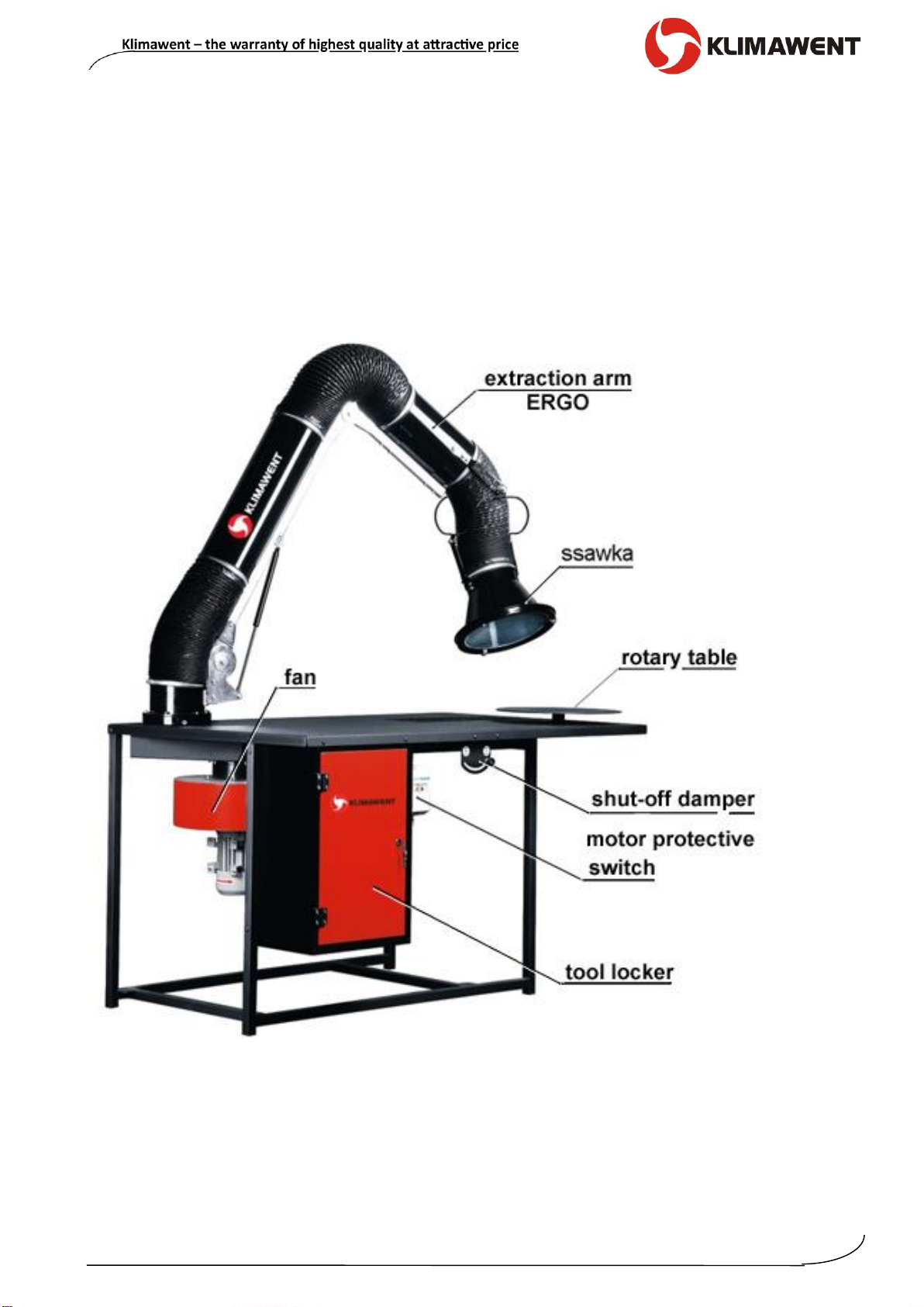
11.10.2016 welding station ERGO-STW-R
The extraction fan ought to be connected to the ventilation system to discharge the polluted
air outside the process room. Whereas, in the lower part of the device is located a grounding
clamp which has to be connected with the mass cable of the welding machine.
To start the extraction fan, simply, press the pushbutton in the motor protective switch.
6. Assembly and Start-up
The device is designed for operation in closed rooms (indoor application). Simply, it should
be placed stably on an even floor surface, so there is free access of the cooling air access
to the motor and, on the other hand, the control unit and waste-container are accessible for
the operator.
CONNECTION TO THE POWER SUPPLY SYSTEM
Connection to the power supply system ought to be carried out by a person with qualifica-
tions and according to the valid regulations. Prior to connection make sure if the parame-
ters of the existing installation are corresponding with the data on the nominal plate. Prior
to start-up check the connection between the motor and the PE protective cable
and examine the correctness of electrical connections, among others: the impeller rotation
sense should be according to the arrow on the housing. In case of opposite direction, turn
the phase converter inside the plug.
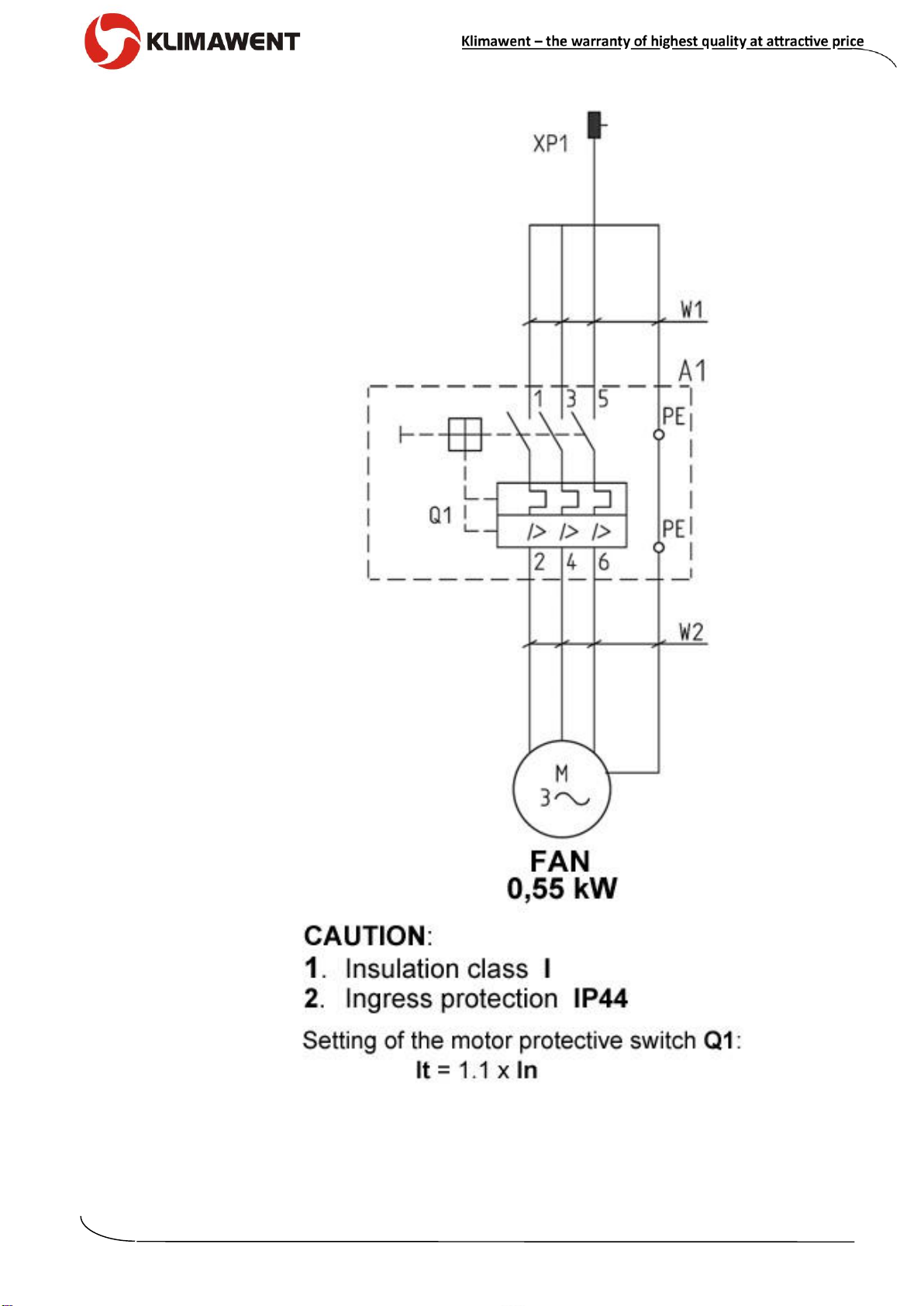
Connection of the fan to the power supply is illustrated in Fig. No.2.
BEFORE THE OPERATION:
Set the hood inlet in a suitable position: not more than 30 cm from the welding arc, and
not less than 20 cm –as the welding chippings (spatters) could damage the hood surface
and the suction stream could interrupt the gas coating (CO2, argon).