KLINGER SCHÖNEBERG Chemoball KH2F-CI Setup guide

Assembly and Repair Instructions page 1 of 6
release 0
Chemoball KH2F-CI file:Montage-Reparatur-
Anl KH2F-CI_
EN-110429.doc
Provide: Roth/BNi Printed pages will not be updated
Approval: Roth Date: 29.04.2011
Assembly and Repair Instructions for KLINGER SCHÖNEBERG Ball Valves, Type Chemoball KH2F-CI
Table of Contents
1 Validity …………………………………………………..………………………………………………………...… 2
2 General Remarks ……………………………………………….………………………………………………….. 2
3 Construction and Components Chemoball KH2F-CI ………………………..…………………………...……... 3
4 Assembly of the Chemoball KH2F-CI ……………..……………………………………………………………... 4
4.1 Preparing for Assembly …………….………..………………………………………….…………………. 4
4.2 Assembling the Valve ……..………………..…………………………………………….……………….. 4
4.3 Function, Strength and Tightness Test ……..……….…………..…………………….….……..……… 4
4.4 Independent Conversion and Manufacture of Spare Parts …………………..…..…………………… 5
4.5 Incorrect Operation ……………………………..………………………………………………………….. 5
5 Dismantling of the Chemoball KH2F-CI…………………………………………………………………………... 5
5.1 Precautionary Measures …………..……………………………………………………………………… 5
5.2 Preparing for Dismantling …………..……………………………………………….…………………….. 5
5.3 Dismantling ………..……………………………………………………………………………………….. 5
5.4 Final Cleaning and Recording of Damage ……………………………………………………….……… 6

Assembly and Repair Instructions page 2 of 6
release 0
Chemoball KH2F-CI file:Montage-Reparatur-
Anl KH2F-CI_
EN-110429.doc
Provide: Roth/BNi Printed pages will not be updated
Approval: Roth Date: 29.04.2011
1 Validity
These Assembly and Repair Instructions are applicable to the type series listed below:
Chemoball KH2F-CI
2 General Remarks
These Assembly and Repair Instructions are designed to provide assistance in assembling, servicing and
repairing the ball valve Chemoball KH2F-CI.
The valves may only be dismantled and taken apart by skilled personnel acquainted with the assembly,
commissioning and operation of this product.
Trained personnel within the meaning of these Assembly and Repair Instructions are individuals who are able to
assess the work which they have been entrusted and to recognise possible risks in view of their special training,
their know-how and experienceand their knowledge of the pertinent standards.
These instructions as well as the Operating Instructions for KLINGER SCHÖNEBERG Ball Valves must be
observed. KLINGER SCHÖNEBERG GmbH shall no assume no liability for damage or interruptions to operation
arising from incorrect handling or failure to observe these Repair Instructions.

Assembly and Repair Instructions page 3 of 6
release 0
Chemoball KH2F-CI file:Montage-Reparatur-
Anl KH2F-CI_
EN-110429.doc
Provide: Roth/BNi Printed pages will not be updated
Approval: Roth Date: 29.04.2011
3 Construction and Components Chemoball KH2F-CI
Ball Valves
DN15 - DN25
Pos. Part Pos. Part
1 body 13 hex. nut
2 cap 14 cover ring
3 ball 15 cover
4 seat ring 16 stop plate
5 body seal 17 allen screw
6 stem 18 antistatic element
7 seal 19 lever
8 bearing ring 20 allen screw
9 packing ring below / upper 21 hex. screw
10 ring 22 locking plate
11 thrust washer 23 allen screw
12 plate spring 24 stop pin DN15 - DN25

Assembly and Repair Instructions page 4 of 6
release 0
Chemoball KH2F-CI file:Montage-Reparatur-
Anl KH2F-CI_
EN-110429.doc
Provide: Roth/BNi Printed pages will not be updated
Approval: Roth Date: 29.04.2011
4 Assembly of the Chemoball KH2F-CI
4.1 Preparing for Assembly
All parts must be prepared to assemble the ball valve, i.e. the parts are carefully cleaned and laid on a soft base
(rubber mat or similar).
It must be considered that the plastic parts are almost always soft and very sensitive and that in particular the
sealing surfaces may not be damaged.
4.2 Assembling the Valve
The body (1) of the valve must be tensioned securely and safely in a suitable device; free access to the cavity
and stem must be guaranteed.
Before assembling, please take care that all components are clean and free of impurities.
Lightly grease the body (1) in the area of the seat ring with high temperature grease (e.g. Q1) licensed by the
FDA.
Insert seat ring (4) into bore. It should be able to insert it with slight manual pressure. If it fits too tightly or too
loosely the dimensions must be checked.
Similarly grease the cap (2) in the area of the seat ring and insert seat ring (4).
Thread on seal (7) and bearing ring (8) to stem (6).
Push on stem (6) from the inside through the body (1). Sealing parts may not be damaged.
Thread on packing rings (9), ring (10), thrust washer (11) and plate springs (12) from the top on the stem (6).
Tighten with hexagon nut (13) on block. Please take care, that the stem (6) must be locked from the body
side.
Insert the ball (3).
Insert body seal (5) into body (1).
Fit cap (2) carefully into body (1) without damaging the body seal (5).
Coat hexagon screws (21) on the thread with high temperature fat (OKS). Tighten hexagon screws (21)
crosswise gradually until the seal is evenly pressed out and cap (2) is metallically on block with body (1).
Thread on cover ring (14) and cover (15) to the stem (6). Tighten with allen screws (17). For DN 15 to DN 25
also stop pins (24) are inserted into the provided holes.
Push on stop plate (16).
Push on hand lever (19), push on allen screw (20) of the hand lever and tighten.
Thread on locking plate (22) and tighten with allen screw (23).
4.3 Function, Strength and Tightness Test
After assembling the ball valve it must be checked whether it can move freely and whether the ball can turn
unhampered. Finally the ball valve must be subjected to a strength and tightness test in accordance with
EN12266 -1 Nr. P10 / P11 / P12.

Assembly and Repair Instructions page 5 of 6
release 0
Chemoball KH2F-CI file:Montage-Reparatur-
Anl KH2F-CI_
EN-110429.doc
Provide: Roth/BNi Printed pages will not be updated
Approval: Roth Date: 29.04.2011
4.4 Independent Conversion and Manufacture of Spare Parts
Conversion while changing the valve is only permissible after agreement and written declaration by the
manufacturer. Original spare parts and accessories authorised by the manufacturer serve the purposes of safety.
If other spare parts are used and consequences result KLINGER SCHÖNEBERG GmbH shall not assume
liability.
4.5 Incorrect Operation
The operationally reliability of the valve is only guaranteed if it is used correctly in accordance with the operating
instructions for KLINGER SCHÖNEBERG ball valves. The limit value specified in the technical documentation
may under no circumstances be undercut.
5 Dismantling of the Chemoball KH2F-CI
5.1 Precautionary Measures
In order to ensure that any product residue which has remained in the cavity of the valve cannot lead to risk to the
staff performing the dismantling operation, appropriate protective clothing made of chemical and solvent resistant
material is to be worn on the entire body and a resistant facial protection.
For reasons of caution dismantling should be performed via a catch tank. Any toxic gases or vapours must be
extracted so that they may not reach personnel. This also applies to the final cleaning after dismantling has been
completed.
The ball valves must be brought into a pressure-free state for the purposes of repair. For this purpose they should
be brought into the semi-open position. It will similarly benecessary to perform cleaning on the inside and outside
before dismantling. It is expedient to switch the ball several times during cleaning of the cavity.
5.2 Preparing for Dismantling
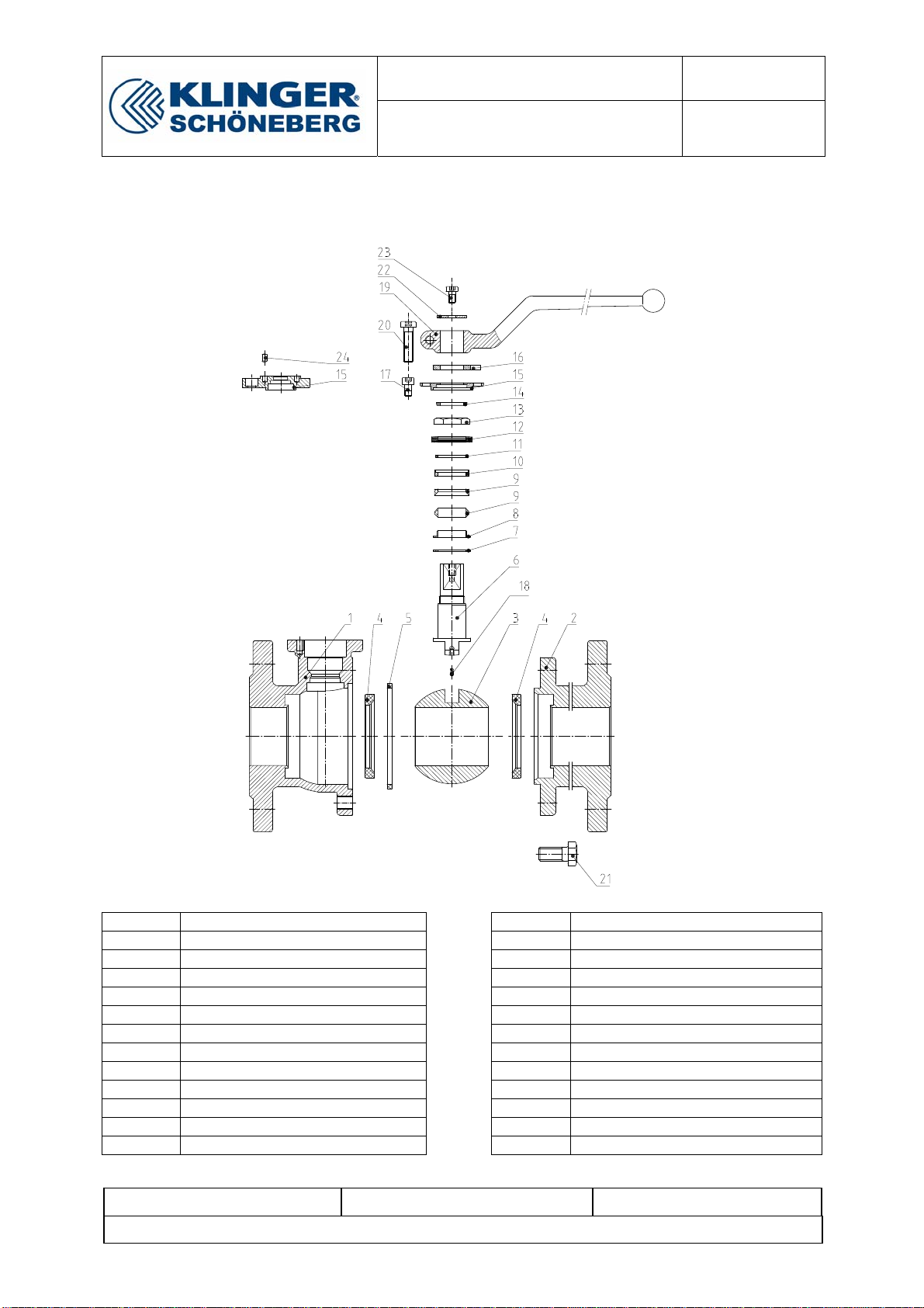
Before dismantling, the body (1), the cap (2) and the parts of the ball valve should be marked so that the
assembly positions can be understood later on.
5.3 Dismantling
For the purposes of dismantling the valve is tensioned again securely and safely in a suitable device. This is done
best on the flange of the body (1) in order to guarantee free access to the intermediate flange, cavity and stem.
Before starting dismantling, the ball valve must be closed.
Unscrew the allen screw (23) and remove the lever (19) and the locking plate (22).
Unscrew the hexagon screws (21) und remove the cap (2).
Take the ball (3) out of the body (1).
Remove the stop plate (16), unscrew the allen screws (17) and remove the cover (15).
Unscrew the hexagon nut (13). Please take care that the stem (6) is locked from the body side.
Plate springs (12), thrust washer (11), ring (10) and packing rings (9) can be removed.
Press the stem (5) from the top into the body and remove it.
Seal ring (7) and bearing ring (8) can be removed.
Seat rings (4) can be dismantled.
Finally the body seal (5) can be removed.

Assembly and Repair Instructions page 6 of 6
release 0
Chemoball KH2F-CI file:Montage-Reparatur-
Anl KH2F-CI_
EN-110429.doc
Provide: Roth/BNi Printed pages will not be updated
Approval: Roth Date: 29.04.2011
5.4 Final Cleaning and Recording of Damage
After dismantling all parts are finally cleaned. The dismantled sealing parts are also to be included in cleaning so
that they may be disposed of with problem.
The damage is then recorded.
Special attention must be paid to inside and outside damage to the body parts. The nature of the sealing surfaces
at the ball seal, stem conduit, body sealing and the flange seals must be checked. The body parts are then jet-
cleaned inside and out with glass pearls and cleaned mechanically if necessary and possible. For this purpose
sealing areas must be covered up.
The valves are then to be cleaned anew and are then available for a further visual check for new assembly.
The stem is checked after visual checking for parallel running and traces of pressure of the two other flanges.
Special attention must be directed at the perfect state of the sealing areas. Slight scratches can be removed with
emery cloth. Damaged or twisted stems are replaced.
The cleaned ball is firstly visually checked. Deep scratches as well as other mechanical damage and chemical
attack on the sealing surface as well as the running surface of the seal ring mean that the ball must be discarded.
Similarly deformation in the area of the ball slit is inadmissible. All screws and sealing parts must be replaced
during every repair.
Table of contents
Other KLINGER SCHÖNEBERG Control Unit manuals

KLINGER SCHÖNEBERG
KLINGER SCHÖNEBERG INTEC K211-HT Series Setup guide

KLINGER SCHÖNEBERG
KLINGER SCHÖNEBERG INTEC K220 Setup guide

KLINGER SCHÖNEBERG
KLINGER SCHÖNEBERG RK-Chemoball Series User manual

KLINGER SCHÖNEBERG
KLINGER SCHÖNEBERG INTEC K221-STD Setup guide

KLINGER SCHÖNEBERG
KLINGER SCHÖNEBERG INTEC Series User manual

KLINGER SCHÖNEBERG
KLINGER SCHÖNEBERG INTEC K411-T&L-STD Setup guide

KLINGER SCHÖNEBERG
KLINGER SCHÖNEBERG INTEC K200-FS Setup guide

KLINGER SCHÖNEBERG
KLINGER SCHÖNEBERG RK-Proball KH 1T M Setup guide