KLINGER KSCICGB User manual

847-336-7556
www.unitedsci.com
1
CAVENDISH GRAVITATIONAL BALANCE
CGB001
DESCRIPTION OF THE INSTRUMENT
The CGB001 Cavendish Gravitational Balance is a miniature version of the apparatus
used by Henry Cavendish in 1797-8 to measure the density of the Earth. The experiment
allows the value of the gravitational constant, G, to be measured, although Cavendish
did not use his version for that purpose. The experiment is remarkable for the ability to
measure an extremely tiny force using simple mechanical means.
The apparatus contains a pendulum system (1, Figure 1) consisting of an adjustable
suspended central rod carrying a small mirror for the optical lever detection system, a
light aluminum cross-piece with two 20g lead balls 10 cm apart, and a light damping
vane. The pendulum is mounted in a massive aluminum housing (2). Two large 1.5 kg
plastic-coated lead balls (4) rest atop light aluminum cylinders on a swivel (4) that enables
the balls to be swung from one side to the other of the apparatus. They can also be
placed onto two circular sliding mounts (6) that allow the distance between the pendulum
and the attracting masses to be varied. The base rests on three leveling feet (6).
An oil reservoir and damping oil (7) as well as a damping magnet (8) are provided.
1
4
2 3
5
Figure 1
3 7
6 8
www.KlingerScientic.com
Cavendish Gravitational Balance KSCICGB

847-336-7556
www.unitedsci.com
2
SPECIFICATIONS
IDENTIFICATION OF THE COMPONENTS
1. Upper suspension rod locknut
2. Pendulum angle adjustment block
3. Suspension rod height adjusting nut
4. Angle indicator disk
5. Angle scale disk
6. Suspension rod locking screw (1 of 2)
7. Upper suspension rod
8. Torsion filament
9. Glass cover plate (1 of 2)
10. Torsion filament connector plate
11. Balance centering plate (2 halves)
12. Concave mirror for light pointer
13. Balance lock actuating screw
14. Balance lock mechanism
15. Small lead ball (1 of 2)
16. Damping oil trough
17. Balance damping vane
18 Aluminum body
19. Swinging support for large lead balls
20. Scale (on base—1 of 2)
21. Base plate
22. Leveling nut (1 of 3)
23. Foot (1 of 3)
24. Sliding ball support (1 of 2)
25. Ball support cylinder (1 of 2)
26. Large lead attracting ball (1 of 2)
27. Damping oil supply tube
28. Damping oil reservoir support
29. Reservoir support set screw
30. Reservoir clip tightening screw
31. Reservoir support clip
32. Damping oil reservoir
33. Balance locking rod
34. Lower suspension rod
Figure 1
www.KlingerScientic.com

847-336-7556
www.unitedsci.com
3
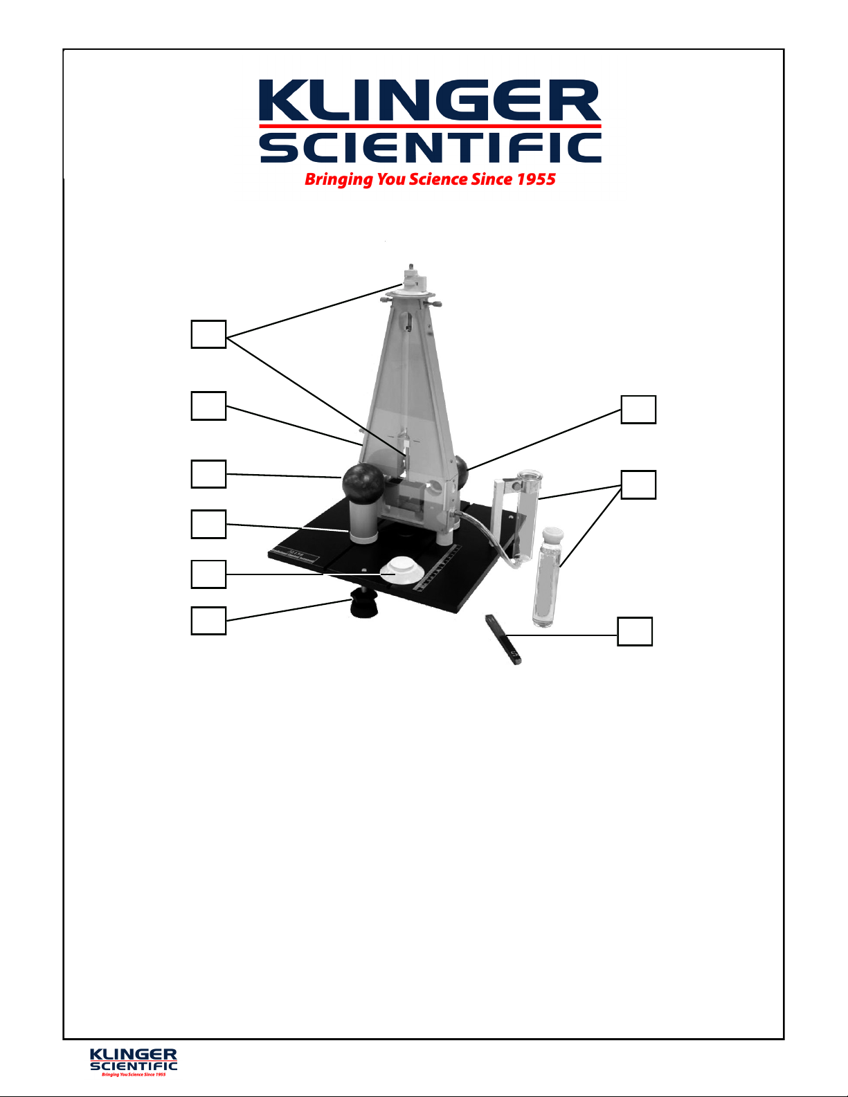
The torsion balance is housed in a solid aluminum main body (18) with glass win-
dows (9) on both sides to eliminate drafts.
The adjusting nut (3) on the top can be used to raise or lower the upper suspension rod
(7) in order to adjust the vertical position of the balance. The angle adjustment block
(2), angle indicator disk (4) and the circular scale (5) are used to read the angle the
balance is rotated from its equilibrium position. The locking screws (6) on the upper
side of the body can fix the upper suspension rod in its angular equilibrium position.
The filament (8), 150mm long and made of beryllium bronze, has connector plates (10)
at each end and connects the upper and lower suspension rods (7,34). A concave mirror
(12) with 2m focal length is mounted on the lower suspension rod. Under the mirror
are the locking rod, a pair of lead balls of 10.0mm diameter (15) and the damping vane
(17), which projects into in a damping trough (16).
The locking screw (13) on the side can raise or lower the locking mechanism
(14).With the locking mechanism lowered, the balance is suspended on the filament
and can rotate freely. When the mechanism is raised, it lifts the balance by the locking
rod (33) and presses the arm of the balance against the body, removing the load from
the filament and immobilizing the balance.
The filament is extremely delicate and the load of the balance stresses it highly. The
balance should only be released and allowed to swing freely when an experiment is in
progress. At all other times, the balance should be locked to preserve the filament.
The main body is mounted on an aluminum base (21). The three leveling screws (22)
under the base are used to level the device. The two grooves on the base serve as
guides for the sliding ball supports (24). The ball support cylinders (25) for the large
lead balls (26) rest on the sliding blocks. The distance between the large balls can be
measured by the scales (20) along the grooves.
The oil damping system is mounted on one side of the base and connected to the
damping chamber (16) through a tube (27).
Mass of large lead balls: Approximately 1.5kg
Difference between the two balls < 0.002kg
Mass of small lead balls: Approximately 0.02kg
Difference between the two balls <0.0005kg
Arm length of the torsion balance: 5.0x10⁻²m
Torsion Filament: Length: approximately 150mm
Cross sectional area: 0.145±0.08mm2
Material: Be-Sn-Cu alloy
Period of the torsion balance 590±10sec.
Scale: 140mm with 1mm divisions
Full-scale error < 0.1mm.
Damping method: Silicone oil
Relative error of Gravitational Constant: < 15%
Operating temperature: 10 –40°C
Relative humidity: < 40%
Operating location: Should be free from vibration, sunlight,
radiant heat, magnetic and electric fields
Dimensions: 300x300x420mm
Net weight: 12kg
www.KlingerScientic.com

847-336-7556
www.unitedsci.com
4
THEORY
The most common methods used to measure the value of the gravitational constant are
the displacement method and the acceleration method.
The Displacement Method
The displacement method is named after the final angular displacement of the torsion
balance to be measured in the experiment. In Figure 2, the torsion balance is set up a
large distance Lfrom a wall or screen with a millimeter scale
. The concave mirror is
illuminated by a laser
, producing a spot of light on the scale. The distance between
the small lead balls, each of mass m, and the axis O is d. The concave mirror is
mounted at the center of the arms connecting the two small balls. The projection system
produces a large displacement of the light spot, s, for a small angular displacement of
the mirror, /2. This allows the user to measure the angle easily, and determine the
angular displacement of the mirror from the central position, /2.
Two large lead balls of same mass Mare placed against the glass windows of the main
body, symmetric to the axis O. Figure 3 illustrates the side view of the arrangement.
The line connecting the centers of the large and small balls is perpendicular to the center
line of the main body, PP’. Figure 2 greatly exaggerates the angles of the balance
for clarity; the deviation of the balance from its central position is extremely small,
so the centers of the small balls are almost on the line PP’, and the torque produced
by the gravitational force Fbetween the large and small balls, N, is given by 2F·d.
When the torsion balance comes to rest, the restoring torque applied by the torsion
filament, N’ is k·/2, where the coefficient k represents the torque in the wire when it is
twisted by 1 degree. Since N = N’, we have 2F·d= k·/2. Therefore
(1)
If we now move the large lead balls to their symmetrically opposite final positions, indicated
by the large dotted circles in Figure 2, the torsion balance will be subjected to a torque
in the opposite direction and will move to the new equilibrium position represented by
Figure 2 Figure 3
d
kF 4
www.KlingerScientic.com

847-336-7556
www.unitedsci.com
5
the dotted line and small circles in Figure 2. Its angle of rotation to the new equilibrium
position can be determined by the displacement S(=2s) of the projected dot on the
scale. The distance from the mirror to the screen being L, and S « L, we have
= S/2L (2)
The torque constant of the wire, k, can be determined from the balance’s period of
oscillation
T
, using
derived from the harmonic motion equation
where the moment of inertia Iis given by
the moments of inertia of the lower suspension rod, mirror, and balance crossbar are
neglected, since they are extremely small compared with those of the lead balls.
Hence the torque constant of the wire kcan be expressed as
(3)
Substituting expressions (2 ) and (3) into (1), we have
(4)
The gravitational force between the large ball Mand the small ball mat a
separation of ris
(5)
Combining expressions (4) and (5) to eliminate F, we have the formula for the gravitational
constant G:
(6)
Where ris the distance between the centers of the large and small balls, dthe length of
the arm of the torsion balance, Sthe maximum displacement of the light dot, Mthe
mass of the large lead balls, Tthe period of oscillation of the balance, and Lthe distance
from the mirror to the scale.
Strictly speaking, distance rbetween the balls in Figure 2 should be
However, the error caused by the approximation will not exceed 2% so that it can be
neglected.
k
T1
2
k
dt
d
I
2
2
iii mddmdmrmI 2
2
22
2
11
22
2
2
2
2
284
T
md
T
I
k
LT
mdS
L
S
T
md
dd
k
F
2
2
2
22
2
8
4
1
4
2
r
Mm
GF
LMT
dSr
G
2
22
L
dS
rdrr 42
"
www.KlingerScientic.com

847-336-7556
www.unitedsci.com
6
There is a second, more important correction, illustrated by Figure 4. The small ball m
is subjected not only to the force Fapplied by the large ball M1, but also to a force f
applied by the large ball M2. Therefore, the value for Gobtained from expression (6)
needs to be corrected.
In Figure 4, the distance between mand M2is
But and so,
(7)
If the component of f in the opposite direction to Fis f’, then
(8)
Substituting expression (7) into expression (8), we have
where
(approx. 0.074)
Here dis the arm length of the torsion balance (0.05m), and rthe distance between
the centers of the large and small balls, which can be determined from
Where His the thickness of the main body (approx. 0.025m), hthe thickness of the
glass window (approx. 0.002m), and D the diameter of the large ball (approx. 0.0635m).
Figure 4
22
4dr
2
r
Mm
GF
21
MM
F
dr
r
dr
Mm
Gf
22
2
22
44
22
4
'
dr
r
ff
F
dr
r
F
dr
r
dr
r
Ff
2
3
22
3
22
22
2
4
4
4
'
2
3
22
3
4dr
r
22
D
h
H
r
www.KlingerScientic.com

847-336-7556
www.unitedsci.com
7
The force actually acting on the small ball is
Substituting this into expression (4), we have
Since
the corrected expression for Gis
(9)
The Acceleration Method
The acceleration method determines the value of Gfrom the acceleration produced by
the gravitational force.
As in the case of final displacement method, the large balls are first moved to the positions
against the glass windows and when the small balls have come to rest, the torque
produced by the gravitational force will balance the torque in the wire due to the rotation.
When the large balls are now moved to the dotted position shown in Figure 5, the initial
force on the small ball F’ will be the sum of the gravitational force Fand the elastic
restoring force, f. Therefore, we have
(10)
The small ball moves a small distance lunder F’. The motion can be regarded as a
uniformly accelerated over the first short period of time (within 90 seconds). Therefore
FFFfF
1'
LT
mdS
F2
2
1
2
r
Mm
GF
LMT
dSr
G
2
22
1
1
Figure 5
2
22'
r
Mm
GFfFF
www.KlingerScientic.com

847-336-7556
www.unitedsci.com
8
we can apply Newton’s Law
where ais the acceleration.
Substituting into (10), we have
(11)
Expression (11) can be corrected to take into account the gravitational force applied by
the second large ball:
(12)
If the distance traveled by the small ball is l, we have
In order to solve this equation for a, we need to find the distance lthat the small ball
has traveled in the first tseconds after the large ball was moved into the dotted
position (Figure 5).
From Figure 5 we have
Therefore
So the acceleration acan be determined from
(13)
Substituting (13) into (12), we have
The acceleration method is simpler than the displacement method. However, although
it requires 1—2 hours to stabilize the instrument in its initial position, this is still only
half the time required for the two stabilizations needed in the displacement method.
Also, the error in the Gvalue obtained by the acceleration method is usually larger.
The Inverse Proportion Verification
The apparatus allows the separation of the small and large balls to be varied by
supporting the large balls on two light aluminum cylinders (24 & 25 in Figure 1) that
slide in grooves on the instrument base. This method can be used to verify the relation
between the gravitational force and the distance between the objects:
From expression (4)
maF'
M
ar
Mm
Fr
G22
22
M
ar
G2
1
2
2
2
1atl
d
l
L
S2
2
2
1
2at
L
dS
l
Lt
Sd
a
2
2
2
2
1
MLt
Sdr
G
2
1
r
F
LT
mdS
F
2
2
www.KlingerScientic.com

847-336-7556
www.unitedsci.com
9
therefore
So the relationship between F and r will be verified if we can show experimentally that
Figure 6 illustrates the change in the distance rbetween the large and small balls.
Record the displacement S of the light dot and the corresponding distance rthen plot
1/r2vs. S on graph paper to verify that the relationship between F and 1/r2is linear.
Since each small ball is also subjected to the force of the second large ball, the Svalues
obtained above will be too small and need to be corrected by replacing Swith (1+
)S.
SETUP
The experiments described in this manual require the following accessories:
Laser (He-Ne or diode) and support material
Stopwatch (electronic or mechanical, 1/100 s)
3m tape measure
Screen and support material
Vernier caliper
Balance (2000g capacity x at least 1g resolution)
Calculator.
Leveling
Choose a location as free of vibration as possible and place the instrument on a
solid, level surface.
Set up the laser and the screen as indicated in Figure 2
Measure and record the masses of the large lead balls.
Gently turn the locking knob (16, Figure 1) counter-clockwise to unlock the torsion
balance so that it hangs free on the suspension filament.
NOTE: The suspension filament is extremely delicate and is highly stressed when
bearing the load of the torsion balance. Avoid sudden or jerky movements when
releasing or locking the balance.
Use the adjusting nut (3) to center the small balls vertically in their cutouts in the
main body.
Adjust the position of the laser so that the light beam is incident at the center of the
mirror and reflects onto the screen.
SF
2
1
r
S
Figure 6
www.KlingerScientic.com

847-336-7556
www.unitedsci.com
10
Use the leveling screws (22) to adjust the angle of the apparatus so that the lower
suspension rod (34) hangs in the center of the hole in the balance centering plate
(11).
Apply torsion to the filament using the angle adjustment block (2) until the small
balls just touch the glass window, then finely adjust the leveling screws for the largest
displacement of the light dot on the screen. Then return the angle adjustment block
to its original position.
Centering
In equilibrium, the torsion balance should be centered as shown by the black balance in
Figure 7. Otherwise the user should do the following:
Determine the equilibrium position: Let the torsion balance oscillate with a large
amplitude so that the small balls touch the glass windows. Mark the two end posi-
tions of the light beam on the screen and connect them with a straight line. The
center of the line will be the desired equilibrium position of the balance, x.
Confirm the equilibrium position: Use the damping magnet to reduce the amplitude
of the swing. (The lead balls are diamagnetic and experience a weak repulsive force
near the pole of a magnet. Applying this force alternately to each lead ball as it
passes the center point of the swing will reduce the swing amplitude) Then record
the end positions of the light dot on the screen as shown in Figure 8.
The equilibrium position xcan be calculated as follows. For the damped motion we have:
or
Figure 7
Figure 8
k
xx
xx
xx
xx
2
3
1
2
'
'
'
'
312
31
2
2
2
'
xxx
xxx
x
www.KlingerScientic.com

847-336-7556
www.unitedsci.com
11
If x’ = x, the balance is in its equilibrium position. If not, adjust the angle adjustment
block (2) and repeat the measurement until x = x’.
EXPERIMENTS
A The Displacement Method
1. Measurement of the period of the torsion balance
With the balance swinging with a moderate amplitude and not touching the glass
at the end points, observe the light dot on the screen and start the timer when
the light dot passes the equilibrium position Stop it at the same point in the cycle
after the torsion balance has completed 2 or 3 oscillations. Average the times to
find the period T. NOTE: Very small amplitudes will yield less accurate results.
Alternative method: With the balance swinging with a moderate amplitude
and not touching the glass at the end points, observe the light dot on the screen
and record its position every 15 s for 15-20 minutes. Draw a graph of the position of
the light dot vs. time and determine Tfrom the graph.
2. Measurement of Gwith oil damping
Fill the oil cylinder with oil up to the mark. Lift the cylinder slowly so that the oil
will flow into the damping chamber. Stop the process when the damping
plate is submerged in the oil. (Due to the buoyant force and surface tension of
the liquid, the equilibrium position may deviate. In that case, use the angle
adjustment to readjust the equilibrium position x.)
Place the large balls in the initial positions shown (with solid lines) in Figure 2. It
will take approximately 20 minutes for the small balls to come to rest. Record
the position of the light dot every minute until it stops moving.
Carefully move the large balls to their final positions and observe the movement
of the light dot. Record the position of the light dot every minute until it stops
moving.
Using the above data, draw a graph with x-axis representing time and y-axis
representing the position of the light dot. Determine the maximum displacement
of the light dot, S.
3. Measurement of Gwith air damping
For each position of the large balls, record several end points of the swings and
graph them as shown in Figure 8.
Select three consecutive end points of the light dot in the graphs of both large
ball positions and calculate the equilibrium positions of the light dot in each case
using the mean value method:
The maximum displacement is
312
31
2
2
1
2xxx
xxx
Y
312
31
2
2
2
'''2
'''
xxx
xxx
Y
12
YYS
www.KlingerScientic.com

847-336-7556
www.unitedsci.com
12
Example:
In an experiment using air damping, the experimenter measured the following
quantities:
Mass of each large lead ball, M: 1.520 kg
Projection distance, L: 2.124 m
Period of the torsion balance, T: 596.3 sec.
Distance between the large and small balls, r: 4.75x10⁻² m
Length of the balance arm, d: 5x10⁻²m.
When the large balls were at their initial positions, three consecutive end points of
the light dot were measured to be:
x1= 370mm
x2= 510mm
x3= 395mm
therefore the equilibrium position is
= (5102-370x395)/(2x510-370-395)
= 446.86mm
When the large balls were at their final positions, three consecutive end points of the
light dot were measured to be:
x’1= 475mm
x’2= 545mm
x’3 = 483mm
therefore the equilibrium position is
= (5452-475x483)/(2x545-475-483)
= 512.12mm
The displacement of the light dot is
= |512.12 –446.86| = 65.26mm
Substituting Sinto expression (6),
= (3.14162x(4.75x10-2)2x5x10-2x6.526x10-2)/(1.52x596.32x2.124)
= 6.329x10⁻¹¹Nm2/kg2
After correction,
G’ = (1+
)G = 1.074x6.329x10-11
= 6.797x10⁻¹¹Nm2/kg2
The relative error,
, is
% = 1.87%
where the standard value G0is 6.672x10⁻¹¹Nm2/kg2
100
'
0
0
G
GG
312
31
2
2
1
2xxx
xxx
Y
312
31
2
2
2
'''2
'''
xxx
xxx
Y
12
YYS
LMT
dSr
G
2
22
www.KlingerScientic.com

847-336-7556
www.unitedsci.com
13
B The Acceleration Method
Do not use the damping oil for this method. Drain the oil from the main body by
lowering the oil cylinder –the oil will flow back into the cylinder.
Place the large balls in their initial positions as shown by the solid lines in
Figure 5. Wait for 60 to 120 minutes for the light dot to come to rest.
Carefully move the large balls into their final positions against the glass windows.
Make sure they do not touch the windows.
Star the stopwatch immediately and measure the position of the light dot every
15 seconds for 120 seconds. Table 1 shows sample data from an experiment
with L = 2.27 m.
Plot a graph with x axis representing time squared t2and y axis representing the
displacement S. Calculate the acceleration from the slope of the graph and
substitute it into expression (11) for G’.
The acceleration equation for the small ball
can be rewritten as
Letting Y = S and X = t2, we have a linear equation
The slope of the linear equation can be determined using the least squares fit
procedure. In order to illustrate this, we will select the data for tbetween 45
and 90 sec from Table 1 for the calculation (Generally, greater errors occur
before 30s and after 90s). See Table 2.
From Table 2,
Xi= 19350
XiYi= 485.0
Yi= 8.55x10⁻²
Xi2= 1.143x10⁸
t
(s)
0 15 30 45 60 75 90 105 120
x
(cm)
52.0 52.3 52.8 53.2 53.8 55.5 56.4 57.3 58.2
Table 1
Lt
Sd
a2
2
t
d
La
S
X
La
d
Y
t (s) 45 60 75 90
x (cm) 53.2 53.8 55.5 56.4
S (m, =Y) 0.0120 0.0170 0.0235 0.0330
t2 (= X) 2025 3600 5625 8100
Table 2
www.KlingerScientic.com

847-336-7556
www.unitedsci.com
14
The slope, k, is given by
= (4x485.0-19350x0.0855)/(4x1.143x108-3.744x108)
= 3.44x10⁻⁶
Therefore,
Solving for aand substituting into expression (11),
= ((4.75x10⁻²)2x7.578x10-8)/(2x1.52)
= 5.624x10⁻¹¹Nm2/kg2
After correction,
G’ = (1+
)G = 6.069x10⁻¹¹Nm2/kg2
The relative error,
, is
% = 9.08%
C The Inverse Proportion Method
Fill the damping chamber with damping oil. The equilibrium position of the balance
will have shifted. Recalibrate the equilibrium position and record it.
Place the large balls on the sliding blocks and move them until they touch the
glass windows (see Figure 6). Record the position of the light dot every minute
until it stops moving. Record the final position, x1.
Set the large balls 5.3cm away from the glass (i.e. r2= 5.3cm). Record the position
of the light dot every minute until it stops moving. Record the final position x2.
Repeat the previous step for r3= 6.5cm and r4= 9.2cm.
The differences between the xiand the equilibrium position xwill be the displacements Si
of the light dot. Sample data are shown in Table 3.
The Sihave to be corrected. The correction coefficient
varies with r, so its values
have to be calculated in each case from the formula
= r
3/(r2+4d2)3/2. The corrected
100
'
0
0
G
GG
i i
ii
i i i
iiii
XXn
YXYXn
k2
2
6
1044.3
d
La
k
M
ar
G2
2
r (m) r-2 (m-2) S (m)
(1+
)S (m)
r1=4.75x10⁻² 4.43x1023.2 x10-2 0.079 3.5 x10⁻²
r2=5.30x10⁻² 3.56 x1022.6 x10-2 0.103 2.9 x10⁻²
r3=6.50x10⁻² 2.37 x1021.5 x10-2 0.162 1.7 x10⁻²
r4=9.20x10⁻² 1.18 x1020.6 x10-2 0.310 0.8 x10⁻²
Table 3
www.KlingerScientic.com

847-336-7556
www.unitedsci.com
15
values are shown in Table 3.
A graph of (1+b)S vs. r2can be plotted with the data in Table 3. See Figure 9. The
graph verifies the linear relationship:
MAINTENANCE
Lock up the torsion balance with the locking knob after each experiment.
When putting away the accessories, handle the lead balls with extra caution.
Set the oil tank to its lowest position to empty the damping chamber, then pour the
oil into the bottle and replace the cap.
Cover the instrument with the dust cover and store it in a cool, dry and clean place.
Should the filament be accidentally broken and need replacement, follow the
instructions in the appendix.
NOTES
When filling the damping trough with oil, allow the oil to flow in only slowly to mini-
mize the disturbance to the suspended torsion balance. Fill the trough until the
vane is completely submerged by about 1 cm, but do not fill oil above the mark.
When choosing a suitable location for the apparatus, avoid areas with uneven heating
(e.g. drafts, periodic sunshine, nearby heating vents, etc.) The ideal location would
have an even temperature of 20°±5°C. Also avoid areas near magnetic or electric
fields. Uneven heating, magnetic or electric interference can lead to poor measurements
.
Place the lead balls on their supports some time before the experiment to allow
their temperature to equilibrate. Do not handle the lead balls unnecessarily.
Before the experiment, check the thickness of the apparatus body and glass covers
(H + 2h) to at least 0.02mm with a vernier caliper. Similarly check the diameters
(D) of the large lead balls. Set r = h + (H + D)/2.
If the light spot appears to be stuck or in irregular motion during an experiment,
Figure 9
2
1
r
SF
www.KlingerScientic.com

847-336-7556
www.unitedsci.com
16
the cause could be air convection due to temperature change, oil flowing into or out
of the damping trough, a build-up of electrostatic charge, or external vibration
nearby (air conditioner, compressor, refrigerator, footsteps, etc.) To obtain optimal
performance, conditions should be kept as calm as possible. Avoid touching the
apparatus or the bench, moving chairs around, etc., as much as possible.
APPENDIX
Changing the suspension filament
Changing a broken suspension wire on the Cavendish Gravitational Balance requires
patience and a steady hand.
You will need:
A small Phillips head screwdriver (#0)
Fine pointed tweezers
Replacement wire set
IMPORTANT NOTE:
The high strength beryllium bronze wire is very brittle and easily breaks at defects such
as nicks and kinks. Once kinked, the wire cannot be straightened without it breaking
under load. Take great care to avoid any stresses, twists, or kinks when handling the
wire during replacement, as such defects will almost certainly lead to immediate failure.
Even wires which appear perfect sometimes will have minute
nicks and cracks. It is not unusual for a successfully replaced wire
to break as soon as the weight of the pendulum is applied to it.
Figure 1 shows a typical failure of this kind. Five replacement
wires are provided, and you should expect one or two such failures
in a typical set of five.
Procedure:
Removing the broken wire:
1. Remove and set aside the two long upper aluminum sheet side
pieces that secure the glass front and back covers.
2. Supporting the glass panels in place with your hand, remove and set
aside the two short aluminum sheet lower side pieces. Take care not
to lose the small celluloid covers over the side holes (Figure 2).
3. Carefully remove and set aside the glass front and back panels.
Figure 1
Figure 2
www.KlingerScientic.com

847-336-7556
www.unitedsci.com
17
4. Using the pendulum locking mechanism
screw on the left side of the instrument,
carefully raise the pendulum until it is
secured against the body of the case at the
top of the pendulum cutout. Be careful not
to over-tighten the mechanism, as this can
bend the pendulum arm.
5. Using the nut and locknut on the angle
adjustment at the top of the instrument (Figure 3),
raise the bottom of the upper wire suspension rod until it is in the wide cutout (Figure 4)
and arrest it with the two side set screws.
6. Supporting the suspension rod from behind with your finger, loosen the set screw of
the upper wire lug using a small Phillips screwdriver and remove the lug with tweezers.
Loosen the pendulum arresting mechanism slightly and turn the pendulum about
45°. Loosen the set screw of the lower wire lug using a small Phillips screwdriver
and remove the lug from the pendulum with tweezers.
Installing the new wire:
1. Carefully open the package of replacement
wires. Orient the board on the packaging with
the screws securing the wires facing up (Figure 5).
2. Carefully remove the screws holding one of
the wires with a small Phillips screwdriver.
Take care not to move the lugs during this op-
eration to avoid creating kinks in the wire.
3. Close the package over the wires and board
and turn the closed package upside down.
4. Open the package and gently remove the
board by lifting it straight up, leaving the
released wire lying on the packaging.
5. Carefully grasp the lug on one end of the wire with fine tweezers. Hold the lug
against the packaging with the tweezers, and using your other hand gently tilt the
wire and package together until the wire is hanging vertically. Gently remove the
packaging, leaving the wire hanging from the tweezers.
6. Being careful not to bend or kink the wire, slide the lug into place under the head of
the set screw on the upper suspension rod.
7. Carefully supporting the upper suspension rod from behind with your finger, gently
tighten the set screw. The lug should be square on the support.
8. Using the pendulum locking mechanism screw on the left side
of the instrument, carefully lower the pendulum until the lug on
the lower end of the wire hangs free (Figure 6).
9. Allow the wire to “hang out” for 30 minutes so that any tensions in
the wire can relax.
10. Gently raise the pendulum until the lug hangs a little below its
place on the pendulum stem. If necessary, use the point of the
tweezers to gently guide the lug so that is does not “hang up”
Figure 3 Figure 4
Figure 5
Figure 6
www.KlingerScientic.com

847-336-7556
www.unitedsci.com
18
on the end of the pendulum stem or the head of the set screw.
DO NOT ALLOW THE WIRE TO KINK AT THE LUG SOLDER POINT!
11. If the pendulum is not already angled, loosen the pendulum arresting mechanism
slightly and turn the pendulum about 45°.
12. Gently grasp the free lug with the tweezers, raise it a little so that the slot matches
the set screw head position, and gently slide the lug into place under the head of
the set screw.
DO NOT TWIST THE LUG ABOUT THE HORIZONTAL AXIS DURING THIS OPERATION; A
KINK CAN EASILY BE FORMED AT THE ATTACHMENT POINT.
13. Carefully supporting the pendulum stem from behind with your finger, gently
tighten the set screw. The lug should be square on the support, and the wire should
not be taut.
14. Check that the loop of the loose wire does not project beyond the plane of the
housing in the front or back. If it does, gently raise the upper suspension rod to re-
tract it, but do not tighten the wire.
15. Re-assemble the glass plates, celluloid strips, and aluminum sheet side pieces to
the instrument. The celluloid sheets attached to the glass plates go on the inside.
Gently release the pendulum until it hangs free on the wire.
NOTE: If there are any kinks or hidden nicks in the wire, it may break at this point.
Even if this does not happen, it may still break in the next 24 –36 hours as the internal
tensions in the wire relax under the pendulum load. Allow the pendulum to hang
undisturbed for this time before adjusting is height and angle.
www.KlingerScientic.com
Table of contents