KMP T-28 Trojan User manual

Picture may not be the same as actual product. Please refer to actual product.
We reserve the rights of updating product information, appearance and parameters without notice.
Instruction Manual
Specifications:
Wingspan: 2037mm (80.2 in)
Length: 1677mm (66 in)
Wing Area: 65.5dm2 (1015.3 sq in)
Flying Weight: 7.6kg (16.7 lbs)
Engine(not incl.): 45-50cc Gas
Radio(not incl.): 7ch, 11 servos
Construction: Fiberglass Fuselage and Balsa Wings
Features:
High performance scale warbird with great details
High-quality, prepainted, fiberglass fuselage and cowling
High-quality balsa and plywood material
Light weight and strong construction
Hidden switch hatch design
Functional scale flaps
Hardware package included
Scale color scheme with professional covering
Decals pre-applied at factory
Item No: AL001

21
Table of Contents

Congratulations on the purchase of this model airplane. You will enjoy one of the most thrilling
experiences the radio control hobby has to offer.
The product is a professionally built, radio control model. It is very important that you operate this
model responsibly. Please read this instruction manual thoroughly and follow the directions.
This is a sophisticated hobby Product and not a toy. It must be operated with caution and common
sense and requires some basic mechanical ability. Failure to operate this Product in a safe and
responsible manner could result in injury or damage to the Product or other property. This Product is
not intended for use by children without direct adult supervision. The Product manual contains
instructions for safety, operation and maintenance. It is essential to read and follow all the instructions
and warnings in the manual, prior to assembly, setup or use, in order to operate correctly and avoid
damage or injury.
This model is controlled by a radio signal that is subject to interference from many sources outside your
control. This interference can cause momentary loss of control so it is advisable to always keep a safe
distance in all directions around your model, as this margin will help to avoid collisions or injury.
Always operate your model in an open area away from cars, traffic, or people.
Never operate the model into the street or populated areas for any reason.
Never operate your model with low transmitter batteries.
Carefully follow the directions and warnings for this and any optional support equipment (radio,
engine, chargers, rechargeable battery packs, etc.) that you use.
Keep all chemicals, small parts and anything electrical out of the reach of children.
Moisture causes damage to electronics. Avoid water exposure to all equipment not specifically
designed and protected for this purpose.
Introduction
Safety Precautions and Warnings
We guarantee this kit to be free from defects in both material and workmanship at the date of purchase.
Limited Warranty & Limits of Liability
20 1
Appendix – Parts and Options

This warranty does not cover cosmetic damage or damage due to acts of God, accident, misuse,
abuse, negligence, commercial use, or modification of or to any part of the Product. This warranty
does not cover damage due to improper installation, operation, or maintenance. This warranty is
limited to the original purchaser and is not transferable. In no case shall our company’s liability
exceed the original cost of the purchased product and will not cover consequential, incidental or
collateral damage. Our company reserves the right to inspect any and all equipment involved in a
warranty claim. Repair or replacement decisions are at the sole discretion of our company. Further,
our company reserves the right to change or modify this warranty without notice.
REPAIR OR REPLACEMENT AS PROVIDED UNDER THIS WARRANTY IS THE EXCLUSIVE
REMEDY OF THE CONSUMER.
As our company has no control over use, setup, final assembly, modification or misuse, no liability
shall be assumed nor accepted for any resulting damage or injury. By the act of use, setup or
assembly, the user accepts all resulting liability.
If you as the purchaser or user are not prepared to accept the liability associated with the
use of this product, you are advised to return this product immediately in new and unused
condition to he place of purchase.
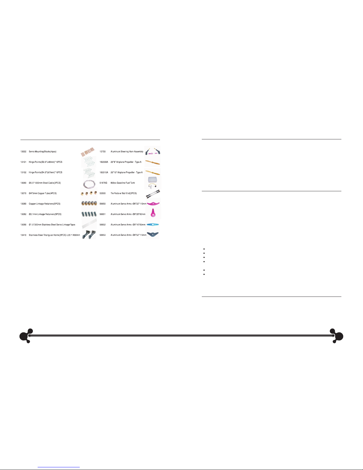
Contents of Kit
2 19
As a large model, the airplane is critical of proper battery use, control linkage setups and flying
techniques. Please pay particular attention to the following areas.
Preflight
Maintain the proper mechanical advantage on all control surface linkages.
Check the radio installation and make sure all the control surfaces are moving correctly (i.e. the
correct direction and with the recommended throws). Test run the engine and make sure it
transitions smoothly from idle to full throttle and back. Also ensure the engine is tuned according to
the manufacturer’s instructions, and it will run consistently and constantly at full throttle when
adjusted. Check all the control horns, servo horns, and clevises to make sure they are secure and in
good condition. Replace any items that would be considered questionable. Failure of any of these
components in flight would mean the loss of your airplane.
Never attempt to make full throttle dives!
Large models perform much more like full-size airplane than small models. If the airframe goes too
fast, such as in a high throttle dive, it may fail. The model should be flown like a full-scale airplane.
Throttle management is absolutely necessary.
Hardware checks
Double-check the setscrews in all control horns to be sure they are very tight. Periodically check
these to be sure they have not loosened over time. Always use threadlock on metal-to-metal
fasteners.
Receiver Battery Selection
Be sure adequate batteries are used to power the receiver. It is recommended that two identical
6-volt receiver packs are used. Each pack must have a minimum of 2700mAh capacity. Use packs of
3000mAh when super high torque servos are used.
Range check
Always range check the radio system per the manufacturer's instructions before the initial test flight
and periodically afterward.
Check the voltage of the on-board packs
ALWAYS use an ESV with a 1-amp load to check the receiver battery packs and the ignition pack
before each and every flight. If there is any doubt that the packs are questionable, DO NOT FLY until
the packs are recharged.
Front Landing Gear Cover for T-28 Trojan

18 3
Radio Equipment
7-channel radio system (minimum)
• 3 standard servos
• 8 hi-torque servos
Recommended Engines
• R-45
• AEROVATE 45CC
• Propeller (consult engine instructions)
• Servo Extensions
• Y-Harness
Adhesives
• 6-minute epoxy
• 30-minute epoxy
• Thick CA glue
• Threadlock
•
Additional Required Items
Tools
• Adjustable wrench (small)
• Drill (drill press preferred)
• Hook and loop straps
• Foam
• Hex wrench
• Hobby knife
• Phillips screwdriver (small)
• Pliers
• Scissors
• Square
• Measuring device (e.g. ruler, tape measure)
The servos used for the control surfaces of this model must have a minimum of 9kg-cm (125 oz-in) of
servo torque. The servos with metal gear are strongly recommended.
Before beginning the assembly of the model, remove each part from its bag for inspection. Closely
inspect the fuselage, wing panels, rudder, and stabilizer for damage. If you find any damaged or
missing parts, contact the place of purchase.
If you find any wrinkles in the covering, use a heat gun or covering iron to remove them. Use caution
while working around areas where the colors overlap to prevent separating the colors.
Servo Selection
Before Starting Assembly
Step 2
Fully assemble the model. With a helper, lift the airplane with your index fingers to find the balance
point. The balance point (CG) should lie between the two marks on the wing. If not, try to move some
parts such as batteries to different position, or add the necessary weight to the nose or tail to obtain
the correct balance.
Correctly balancing the model is critical to its performance and flight characteristics. Checking the
balance on this model is best done with two people.
Step 1
Measure back 25%-28% of the whole wing root’s length
from the leading edge and mark the CG range with a
felt-tipped pen at the wing tip. This is the recommended
center of gravity (CG) range.
Recommended Center of Gravity (CG)
CG

4
Required Parts
Wing panel (left and right)
• Aileron (left and right)
Step 1
Attach the servo arm to the servo when the servo is centered.
Locate the two hard wood blocks for mounting the servo. Use
the servo and two blocks to measure the correct position for
the blocks on the aileron servo cover. Mark the position with
a pen.
•
Section 1 – Aileron Servo and Control
Horn Installation
Step 2
Glue the blocks to the servo cover with epoxy at the marked
position. After the epoxy is fully cured, secure each block to
the cover with a wood screw. Install the servo to the mounting
blocks with provided screws.
Step 3
Plug a servo extension onto the servo. Tie the servo leads
together by using a secure connector, or using a ribbon to
prevent them from coming loose during flight.
Step 4
Tie a weight to a piece of string. A wheel collar works great in
this application. Tie the other end of the string to the servo
extension.
Step 5
Lower the weight into the wing from the aileron servo opening.
Let the weight drop out through the opening near the wing root
for the servo. Use the string to pull the servo lead through the
wing.
Step 6
Install the aileron servo cover with servo to the servo opening
with four screws.
Step 7
Locate the hard wood mounting position for the control horn on
the aileron in line with the servo arm. Install the control horn to
the position using the provided screws.
Step 8
Repeat Steps 1 through 7 for the remaining wing panel.
17
Radio Setup
A 7-channel or greater computer radio is highly recommended. This allows the following features:
• Mixing the right aileron to the left aileron (flaperon mix)
• Electronically adjustable aileron differential
• Mixing the right elevator to the left elevator (dual elevator mixing)
• Independent travel and trim adjustments of each elevator half
When you use a 7-channel or greater computer radio, each servo is plugged into its own separate
channel. Consult your radio manual for specific details on hookup and programming.
The following is our recommended control throws for your reference.
Control Throws
Required Parts
• Fuselage
• Canopy
The canopy are pre-cut to fit the fuselage. Position the
canopy on the fuselage and secure it using provided
screws.
Section 11 – Canopy Installation

5
Required Parts
• Wing panel (left and right)
• Aileron (left and right)
Properly hinging the control surfaces on this model is very important! Poorly installed hinges affect
the model’s precision and control response and can also be dangerous. Each and every hinge needs
to be securely bonded in place in both the flying surface and the control surface. The hinge pivot
points need to be exactly parallel to each other and precisely located on the center of the hinge line.
The control surfaces of this model are predrilled for the hinges included in hardware package.
Step 1
Sand each end of the hinges using coarse sandpaper.
This will improve the bond of the epoxy to the hinge.
Section 2 – Hinging and Sealing the
Control Surfaces
Step 2
Mix some 30-minute epoxy. Using a glue syringe or
toothpick, place a sufficient amount of the epoxy into
one of the hinge pockets in the aileron leading edge.
Install one of the hinge points until the hinge pin
center is flush with the leading edge of the aileron.
Wipe away any excess epoxy with rubbing alcohol.
Continue installing hinges in the leading edge of the
aileron. The control surfaces (ailerons) will be
installed after the epoxy is fully cured.
Note: Be sure that the hinge pivot pins are parallel and flush to the aileron leading edge. It’s
important to frequently mix a fresh batch of 30-minute epoxy in order to achieve good glue
joint penetration. If you notice the epoxy becoming thicker, then mix a new batch!
16
Step 3
When the epoxy is cured, work each hinge throughout its full motion several times using your hands.
This will break free any epoxy that may have found its way into the hinge joint. Move the hinge
throughout its full travel until no resistance is felt.
Step 1
Locate the “V” wing pin and carefully slide half of it into
one wing panel.
Step 2
Carefully slide the remaining wing panel onto the other
half of the wing pin. The fit may be tight; use caution
when inserting the wing panels onto the wing pin.
Step 3
Make sure both wings fit well and there is no gap
between them. Install the joint wings onto the fuselage
with two pins in the leading edge sliding into the holes
provided in the fuselage.
Step 4
Install the belly pan onto the fuselage. Secure the wing
panels and belly pan using the provided wing screws.
Required Parts
• Wing panels • Fuselage
• “V” wing pin
Section 10 – Wing Installation
Step 6
Secure the tail hook hatch cover onto the fuselage with
provided screws.

Required Parts
• Control horn linkages (2)
Step 1
Adjust the linkage length until the holes in the ball links align with the outer hole in the servo arm and
the second hole in the control horn when the aileron is neutral and the servo arm is centered.
Step 2
Attach the ball links to the outer hole in the servo arm
and the second hole in the control horn with screws
and nuts as shown.
Step 3
Repeat Steps 1 through 2 for the remaining servo in
the opposite wing panel.
Section 3 – Aileron Linkage Installation
6
Step 4
Mix some 30-minute epoxy. Place a sufficient amount of epoxy in each of the hinge pockets in one
wing panel.
Step 5
Carefully attach the aileron to the wing, making sure
the hinges are inserted in their respective hinge
pockets. Press the aileron and wing together until the
hinge line gap between the aileron and wing is small
enough. Use a paper towel and rubbing alcohol to
wipe away any visible epoxy around the hinges.
Step 6
Double-check the hinge gap and allow the epoxy to fully cure for enough time. Now is a good time
to repeat Steps 1 through 5 for the remaining wing panel and aileron.
Step 7
When fully cured, move each control surface throughout its travel range several times to break
away any epoxy in the hinge. Be sure to deflect the surface fully.
Note: It’s a good idea to seal the aileron and elevator hinge lines airtight with a piece of
covering to prevent flutter after you finish hinges installation.
15
Step 3
Plug a servo extension onto the tail hook servo.
Tie the servo leads together by using a secure
connector, or a ribbon to prevent them from coming
loose during flight. Secure the servo onto the hard
wood servo mount with screws. Install the servo
with mount into the slot with epoxy.
Step 4
Make a slot on the servo arm as shown.
Step 5
Attach the servo arm to the end of the tail hook. With
the tail hook and the servo in their initial position,
install the servo arm onto the servo using a screw.
Step 2
Slide the tail hook with brace through the hatch
opening in the tail of the fuselage. Mount the brace
into the slot with epoxy.
Required Parts
• Fuselage
• Tail hook
Step 1
Mount the tail hook onto the provided brace with a
screw and lock nut.
Section 9 – Tail Hook Installation

7
Required Parts
• Wing panel (left and right)
• Flap (left and right)
The technique for installing the flap is similar to the aileron installation. Please refer to Section 1, 2,
3 to install the flap. The control horn is pre-mounted in the flap. Install the flap servo with linkage,
hinge the flap, attach the linkage to control horn and secure the flap servo cover with screws to
complete the procedure.
Section 4 – Flap Installation
14
Required Parts
• Stabilizer (left and right)
• Fuselage
• Stabilizer tube
Step 1
The opening for the elevator linkage is highlighted by a
sticker on the fuselage. Carefully drill a hole for the
opening at the highlighted position.
Section 5 – Stabilizer Installation
Step 11
Attach the fuel line from the fuel tank to the carburetor. Make sure the line is from the clunk and not
the vent line.
Step 12
Route the vent line from the fuel tank out of the bottom of the cowling.
Step 13
Make any necessary cutouts to clear the engine components in the cowling. Remove a section from
the bottom of the cowling near the exhaust pipe for cooling outlet as shown. This opening is necessary
to allow cooling air to pass through the cowling to prevent overheating of your engine.
Step 14
Install the cowling onto the fuselage using provided
screws. Mount the propeller and spinner to complete
the procedure.
Step 10
Secure the battery for the ignition inside the fuselage
using a hook and loop strap. Make sure to add a few
pieces of foam between the fuselage and battery to
prevent damage to the battery caused by vibration.
Connect the battery to the ignition switch.
Step 9
Install the switch for the ignition in the switch hatch on
the side of the fuselage as shown.

138
Step 2
Install the elevator servo on the right position of
servo tray in the fuselage. Attach the servo arm to the
servo. Make sure the servo arm is perpendicular (90°)
to the centerline of the fuselage when the servo is at
the neutral position. Install the linkage retainer onto
the outer hole of the servo arm.
Step 3
Locate the hard wood mounting position for the
control horn on the elevator. Install the control horn to
the position using the provided screws.
Step 4
Glue the elevator hinges in place using the same
techniques used to hinge the ailerons.
Step 5
Repeat Steps 1 through 4 for the remaining stabilizer and elevator.
Step 6
Locate the stabilizer tube and carefully slide it into
one stabilizer as deeply as possible. Slide the
stabilizer (with tube) into the stabilizer tube opening
in the fuselage. Make sure the stabilizer anti-rotation
pin slide into the holes provided in the fuselage.
Note: It may be necessary to slightly enlarge the hole in the fuselage for the anti-rotation pin
using a small round file.
Step 6
Install throttle servo with servo arm to the
provided throttle servo mount. Drill a hole
in the firewall for the throttle linkage to pass.
Attach the linkage to the servo arm and throttle.
Step 7
Install the exhaust pipe to the engine. Step 8
Secure the ignition module to the engine
box. Make the connections between the
ignition box and engine at this time.
Step 5
Install engine using four machined aluminum
standoffs, screws and lock washers.
Step 4
Install four screws from the back side of the
firewall. You may apply epoxy glue here.
Step 3
Drill the holes in the firewall for mounting the engine.
Step 2
The vertical and horizontal base lines are pre-marked
on the firewall. Measure and mark the same distance
from the lines for the four engine standoff screws. The
firewall is already mounted correctly to provide right
offset for the engine when the engine standoff center is
on the intersection of the above lines.

12 9
Required Parts
• Fuselage
• Engine and accessories
This model accepts gas engines ranging from 45 through 50cc. The following steps show the
installation of a 45cc gas engine for your reference. The detailed steps may be different when your
selected engine is different.
R-45 Installation
Step 1
Collect the necessary items for the installation of your particular engine.
Section 8 – Mounting the Engine and
Cowling
Step 7
Carefully slide the remaining stabilizer onto the stabilizer tube that projects from the fuselage.
Step 8
Make sure both stabilizers fit well with the fuselage and
there is no gap between them. Secure the stabilizers with
screws at the bottom as shown.
Step 9
Bend one end of the provided steel linkages. Assemble the
provided wood rod with steel linkages on both sides.
Step 10
Slide the heat-shrink tube in place where the wood rod
with steel linkages connect to each other. Use a heat gun
to heat the tube to fix the connection of the wood rod and
steel linkages.
Step 11
Attach the joined linkage to the linkage retainer on the elevator servo arm and the control horn when
the elevator is neutral and the servo arm is centered.
Step 12
Repeat Steps 9 through 11 for the remaining elevator servo and control horn.
Step 3
Assemble the fuel tank correctly. Be sure to use the gas-compatible stopper and fuel tubing.
Step 4
Place foam on the floor of the tank compartment.
Secure the tank in place by wrapping rubber bands or
hook and loop straps around the tank and tank floor.
Later we will run the fuel lines.
Step 5
Locate the hidden switch hatch on the side of the
fuselage and open the hatch. Mount the receiver switch
in the hatch and then close the hatch door.

10 11
Required Parts
• Rudder
• Fuselage
Step 1
The opening for the rudder cable is highlighted by a
sticker on the fuselage. Carefully drill a hole for the
opening on both sides of the fuselage.
Step 2
Install the rudder servo on the right position of servo tray
in the fuselage. Attach the servo arm to the servo. Make
sure the servo arm is perpendicular (90°) to the
centerline of the fuselage when the servo is at the neutral
position.
Step 3
Put the fuselage on its side with rudder virtually
connecting. Using the provided rudder cable, measure a
straight line from the rudder servo arm to the opening in
Step 1, and mark the extension line on the rudder with a
pen.
Section 6 – Rudder Installation
Step 4
Measure rearward 10mm (3/8”) from the edge of the
rudder bevel and make another mark using a pen. The
intersection of the line from Step 3 and this line will be the
position for the rudder control horn.
Step 5
Carefully drill through the rudder at the marked position,
perpendicular (90°) to the rudder centerline at the
marked position. Be especially careful when penetrating
through the backside of the rudder.
Required Parts
• Fuselage
Step 1
Use foam and rubber bands (or hook and loop straps) to
secure the receiver to the battery tray.
Step 2
Wrap the receiver battery in foam and use rubber bands
or hook and loop straps to secure the battery to the
battery tray.
Section 7 – Receiver, Battery and Fuel
Tank Installation
Step 6
Put the threaded rod of the rudder control horn through
the hole and secure it with the provided nuts. Adjust the
position of the rod so that it has the same length on both
sides of the rudder. Screw the molded swivel link with
linkage onto the threaded rod at the right position so that
the rudder cable in operation will not hit the opening of
the fuselage.
Step 7
Hinge the rudder using the same techniques as with the aileron and elevator.
Step 8
Put the rudder in its neutral position and center the rudder servo. Adjust the length of both rudder
cables to match the distance from the rudder servo arm to the control horn. Use a plier to fix the
length of the cables. Install the rudder cables on both sides of the outer holes of the rudder servo
arm and control horn.
Table of contents
Other KMP Toy manuals
Popular Toy manuals by other brands

IncrediBuilds
IncrediBuilds Animal Collection Gorilla Building instructions

Align
Align Trex 700 Electric conversion Nstallation instructions

LEGO
LEGO FRIENDS 41117 Building instructions

Capricorn RC
Capricorn RC LabC03 instruction manual

iKarus
iKarus FUN Piccolo Building instructions

LEGO
LEGO STAR WARS 8097 Building instructions

Tomy
Tomy Starlight Dreamshow Instructions for use

Canon
Canon CREATIVE PARK Sugar Glider quick start guide

LeapFrog
LeapFrog My First Book Hide-and-Seek at the Farm Parent guide & instructions

John Adams
John Adams Golden coin maker manual

Little Tikes
Little Tikes Learn & Play Roll Arounds Assembly instructions

FoxMind
FoxMind SLAM BLUFF quick start guide