KMS FUEL/FA23 User manual


KMS Fuel/FA23 manual
Version 3.01 2
Contents page.
1KMS (Kronenburg Management Systems)............................................................... 3
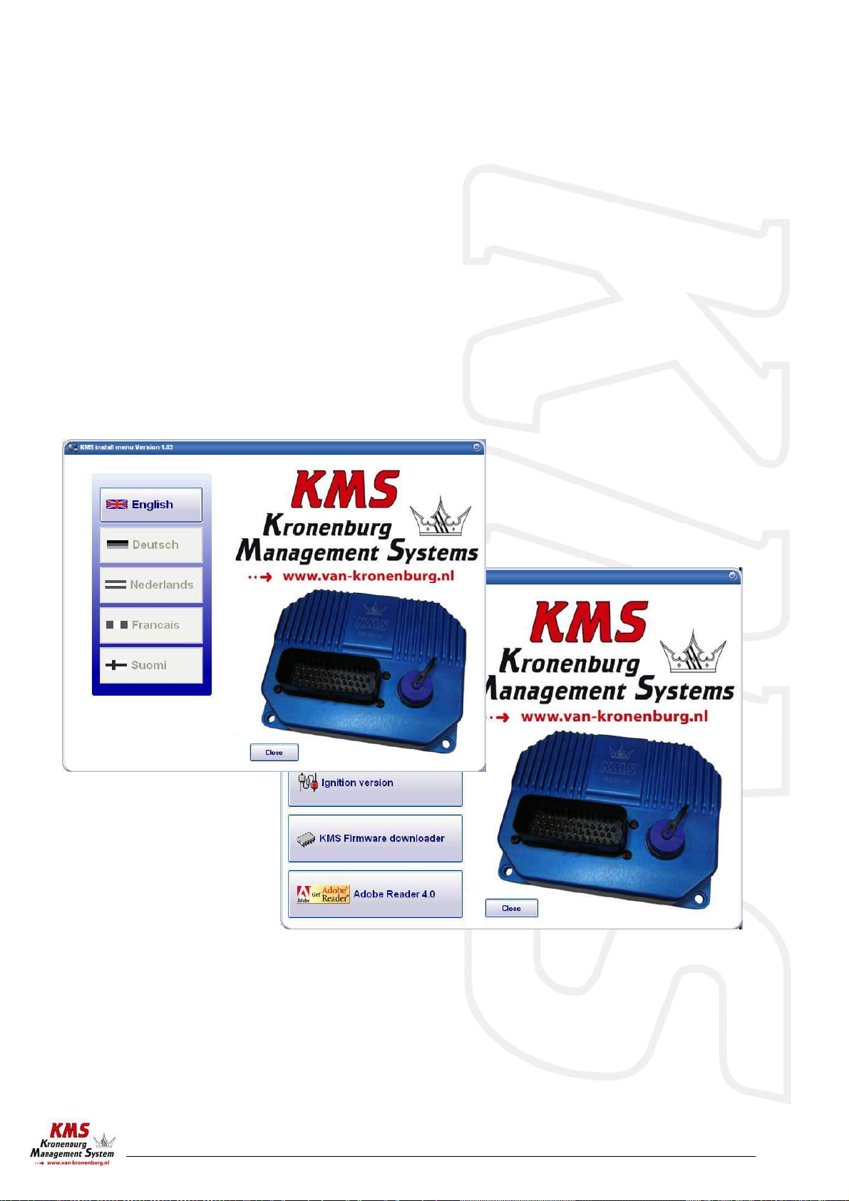
2Software installation....................................................................................... 4
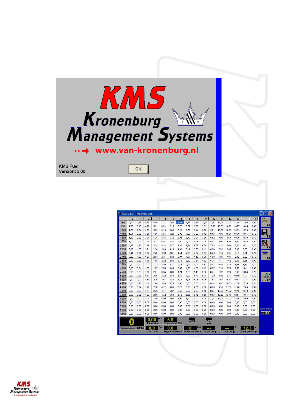
3KMS software................................................................................................. 5
3.1 The injection characteristic diagram ............................................................. 5
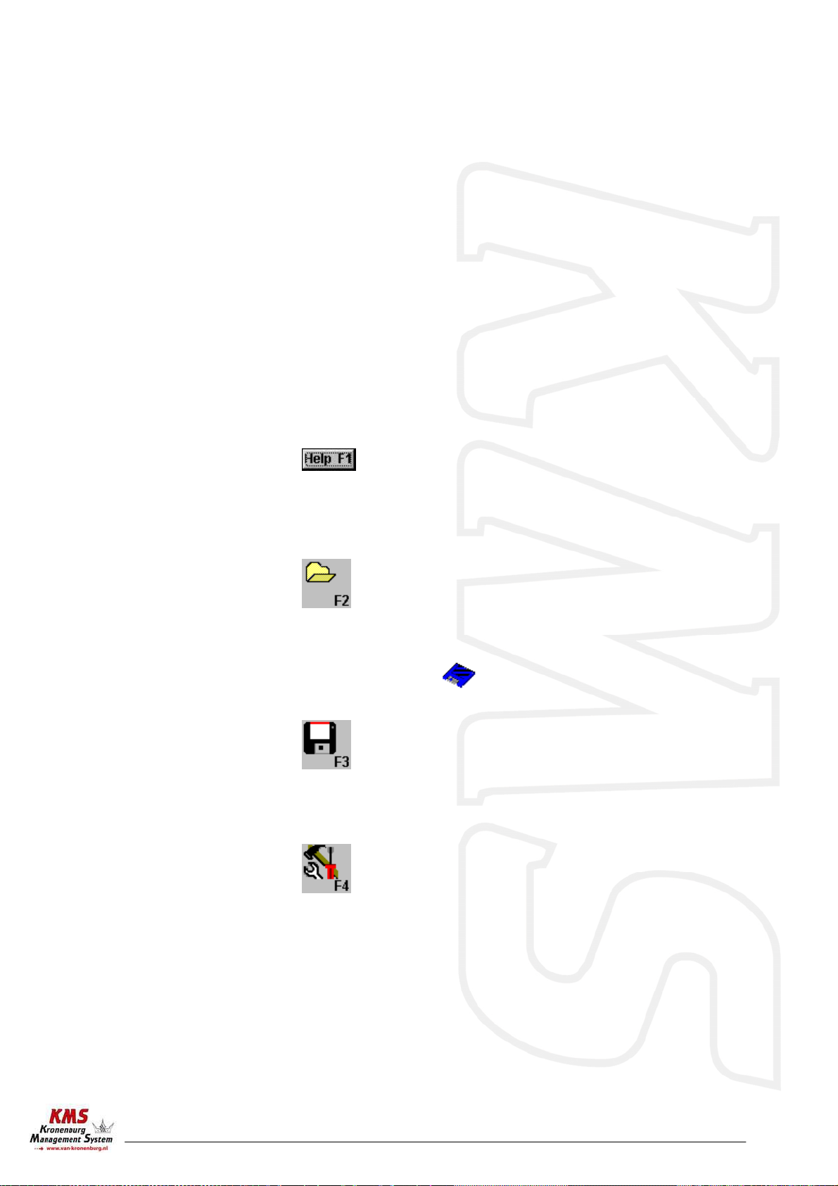
3.2 The function bar....................................................................................... 6
3.2.1 Function key F1 ..................................................................................... 6
3.2.2 Function key F2 ..................................................................................... 6
3.2.3 Function key F3 ..................................................................................... 6
3.2.4 Function key F4 ..................................................................................... 6
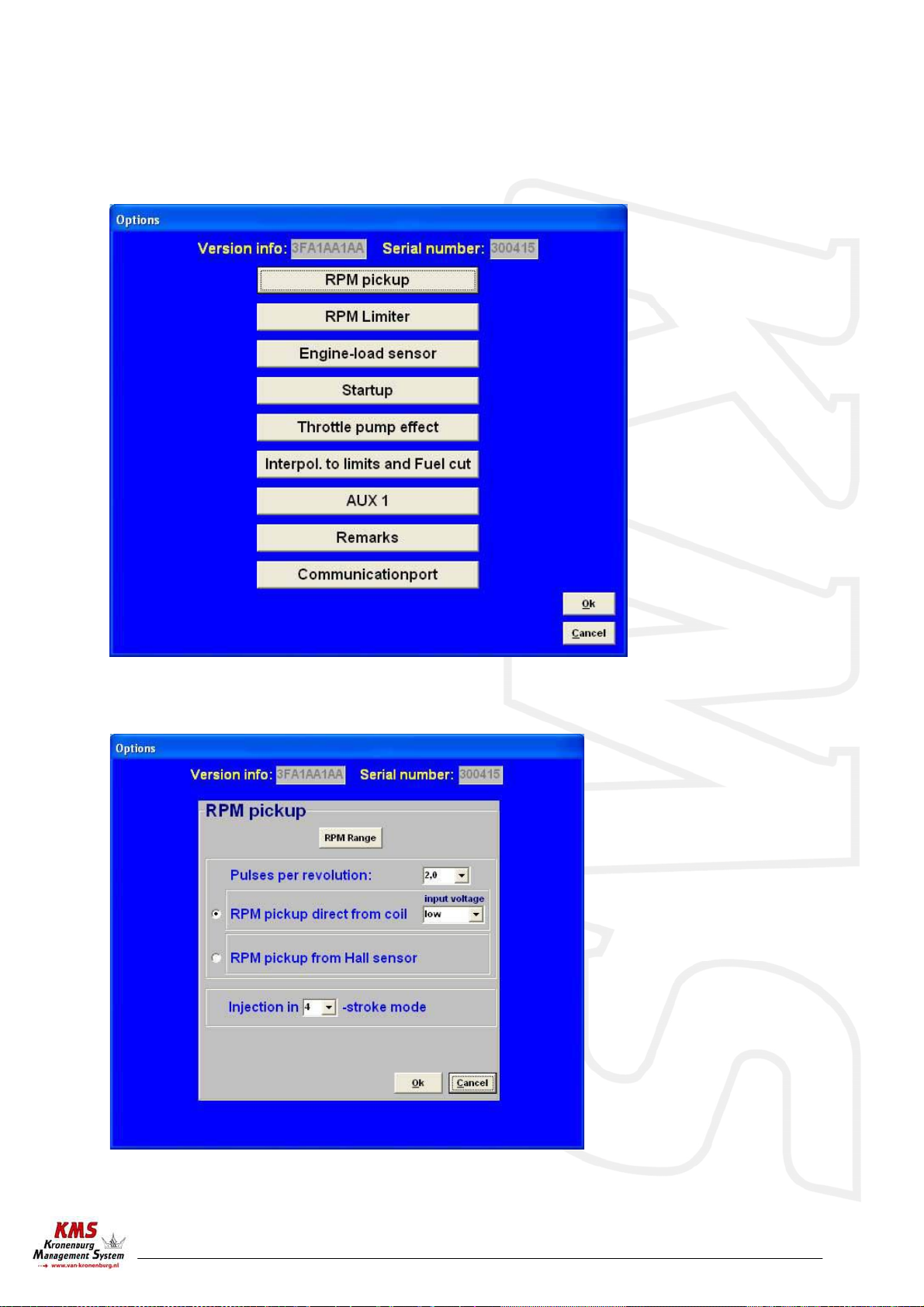
3.2.4.1 Options......................................................................................... 7
3.2.4.1.1 RPM pickup................................................................................ 7
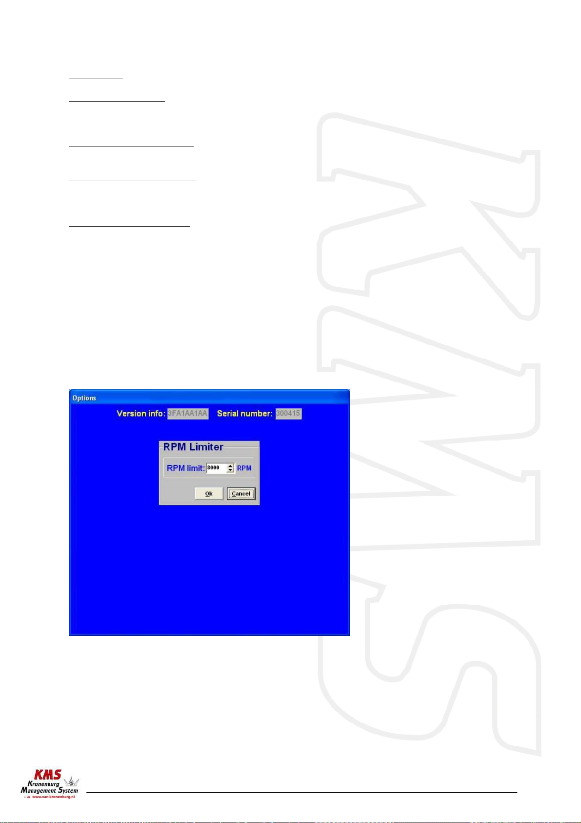
3.2.4.1.2 RPM limiter (not available at older Fuel systems).................................. 8
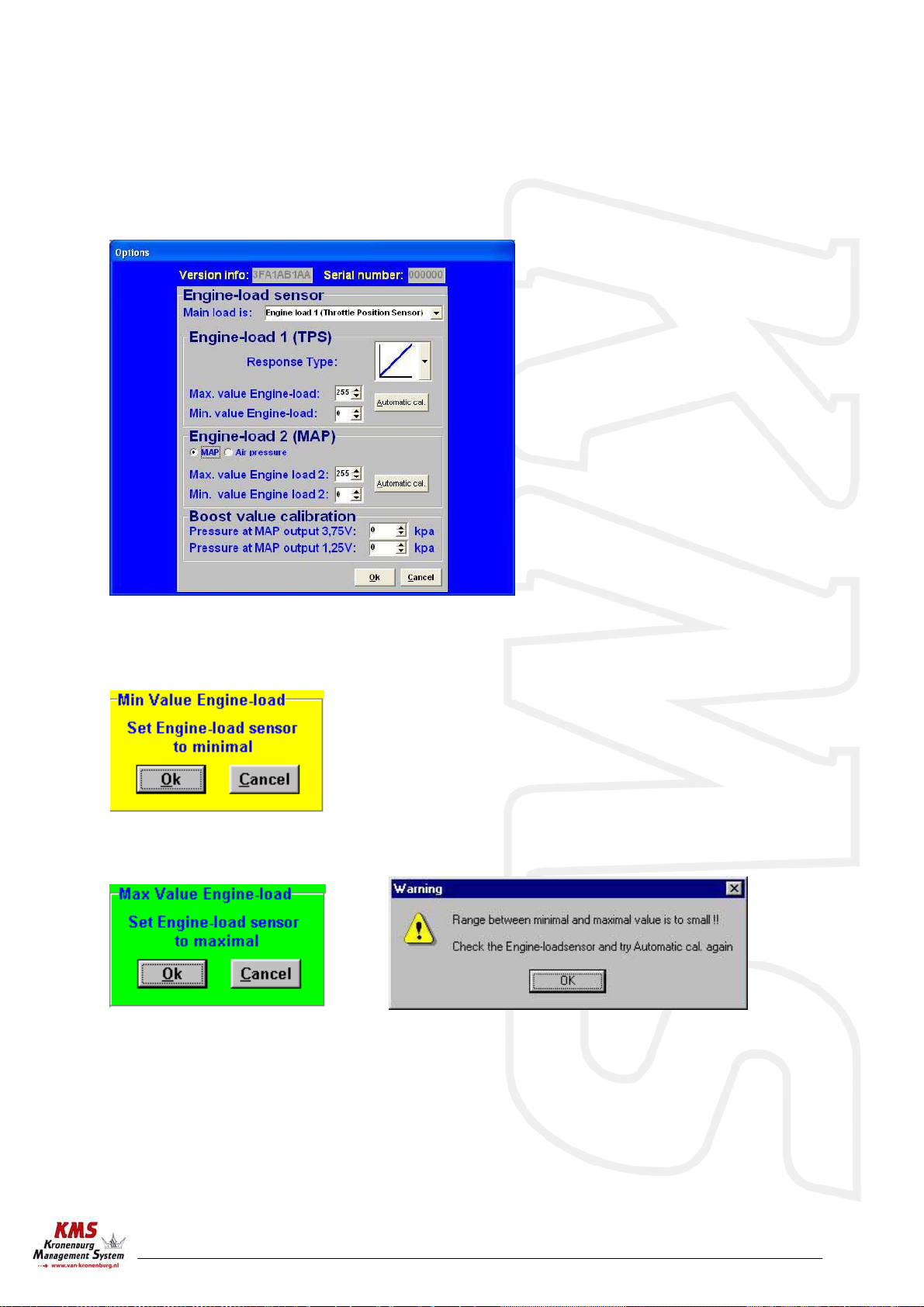
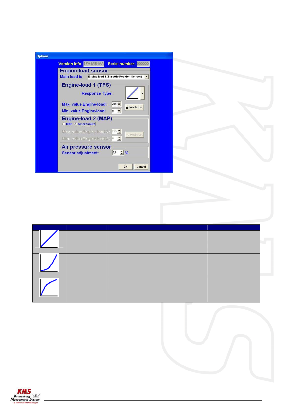
3.2.4.1.3 Engine load sensor....................................................................... 9
3.2.4.1.4 Start-up...................................................................................11
3.2.4.1.5 Throttle pump effect...................................................................12
3.2.4.1.6 Interpolations to limit and fuel cut..................................................12
3.2.4.1.7 AUX 1 (Second stage on older Fuel system) ........................................13
3.2.4.1.8 Correction-table (only for older Fuel systems) ....................................14
3.2.4.1.9 Remarks .................................................................................14
3.2.4.1.10 Communication port .................................................................15
3.2.5 Function key F5 ....................................................................................15
3.2.6 Function key F7 ....................................................................................17
3.2.7 Function key F10...................................................................................18
3.3 The communication bar............................................................................ 19
4Programming ............................................................................................... 21
4.1 Manual changing..................................................................................... 21
4.2 Bar charts ............................................................................................. 21
5Hardware installation.................................................................................... 22
5.1 Fitting the ECU....................................................................................... 22
5.2 Connecting the communication cable........................................................... 22
6Fault tracing................................................................................................ 23
7Specifications .............................................................................................. 24
8Wiring diagram FA23 ..................................................................................... 25
9Wiring examples KMS FA23.............................................................................. 26
10 Wiring example (older) KMS Fuel ...................................................................... 29

KMS Fuel/FA23 manual
Version 3.01 3
1KMS (Kronenburg Management Systems)
This management system can be used as an independent injection system for virtually all types of
Otto engine (engines in which the fuel mix is ignited via a spark plug).
It can also be used in combination with a standard engine management system, to take over the
standard injection at any desired engine speed, boost pressure or throttle valve position. For this
purpose it is mainly applied in compressor or turbo sets.
The set-up of the system software is kept as clear and simple as possible, so that even people with
little computer experience will be able to use this system. Working with the software is simple, but
if the settings are incorrectly configured, there is a serious risk of engine damage. We recommend
you leave the programming to specialists.

KMS Fuel/FA23 manual
Version 3.01 4
2Software installation
The software is supplied together with the system, on a CD-ROM. Installing the software is very
easy. The CD-ROM carries the KMS installation program, which launches automatically when the CD
is inserted.
The program KMS FIRMWARE DOWNLOADER can be used to update the ECU. When there are new
options available, they can be downloaded as a file from our website. With the firmware
downloader this file can be sent to the ECU. (It’s only possible to use this firmware downloader if
you have an KMS ECU with serial nr. higher then 300000)
Once installed, the program is set to work via communication port COM1. If this port is already
being used or not available, another communication port can be used. For the procedure to change
the communication port, see 3.4.1.10.
(USB connections have the most various numbers of communication ports, so make sure you’ve got
the communication port right. For settings and finding the right communication port check
paragraph 3.2.4.1.10)

KMS Fuel/FA23 manual
Version 3.01 5
3KMS software
When the program is started, the main screen will appear, which is composed of three parts:
- The injection characteristic diagram
- The function bar
- The communication bar
The following sections describe the possibilities and functions of the system.
3.1 The injection characteristic diagram
The spreadsheets are two-
dimensional diagrams showing
engine speed against engine load.
The engine speed range can be set
from 500 rpm to 20,000 rpm.
The engine load range is sub-
divided into 16 boxes dividing the
range that has been set for the
engine load sensor.
The rows and columns are shown in
graphs (in the form of bar charts),
when the left mouse button is
clicked on an engine speed or a
load value. For further information,
see section 4.3.
Three types of load-sensors can be used.

KMS Fuel/FA23 manual
Version 3.01 6
1) Throttle position sensor
2) MAP-sensor (Manifold absolute pressure)
3) Air mass/flow meter
In the injection characteristic diagram, figures can be entered that indicate the injector opening
time per injection in milliseconds. This means that at any engine speed and any engine load, the
desired quantity of fuel can be injected.
When the program is started, the main screen will appear, which is composed of three parts:
- The main screen
- The function bar
- The communication bar
The following sections describe the possibilities and functions of the system.
3.2 The function bar
The vertical bar on the right-hand side of the screen shows several function keys, which can be
activated using the mouse arrow or the relevant function keys on the keyboard. An explanation on
the different function keys is given in the following sections.
3.2.1 Function key F1
This function key gives access to the manual in Acrobat reader. Acrobat reader 3.0 or higher is
required. Acrobat reader 4.0 can be found on the installation CD-ROM.
3.2.2 Function key F2
This function key enables a previously saved file to be retrieved from the hard disk, floppy, CD-ROM
etc. The files can be recognised by a blue floppy icon and by the extension .F03
3.2.3 Function key F3
This function key is used to save modified files.
The names of these files automatically receive the extension .F03
3.2.4 Function key F4
When this function key is activated, a menu will appear on the screen, which gives the option of
several settings and tests.
The options will be explained in the following sections.

KMS Fuel/FA23 manual
Version 3.01 7
3.2.4.1 Options
If 'Options' is selected, a menu appears which lists several possible settings. These settings are
described below.
3.2.4.1.1 RPM pickup

KMS Fuel/FA23 manual
Version 3.01 8
In this menu, the settings for the pickup signal and the injection frequency can be entered.
RPM Range: By clicking on the function you can set the rpm range for the main parameter maps.
Pulses per revolution: This is the number of pulses from the hall sensor/coil to determine the
enginespeed. The number of pulses depend on the kind of engine, type of
coil or distributor.
RPM pickup direct from coil: To get a pickup signal from the coil, connect the right wire to the
(-) pole of the coil.
RPM pickup from Hall sensor: To get a pickup signal from the hall sensor, make sure that you
connect the signal wire of the KMS ECU to the right signal pin on the
Hall sensor.
Injection in .. stroke mode: With this option you can set the frequency of injection. 1,2 or 4.
This means for 1 stroke ; injection every half revolution of the
crankshaft.
This means for 2 stroke ; injection every revolution of the
crankshaft.
This means for 4 stroke ; injection every 2 revolutions of the
crankshaft. (recommended)
3.2.4.1.2 RPM limiter (not available at older Fuel systems)
In this screen you can set the RPM limiter to the right maximum RPM of the engine.

KMS Fuel/FA23 manual
Version 3.01 9
3.2.4.1.3 Engine load sensor
Two engine load sensors called "Engine load 1" (for TPS = throttle position sensor) and "Engine load
2" (for MAP = manifold pressure sensors and barometric pressure sensors) can be connected. A MAF
sensor (air mass flow meter) can also be connected. (note : on the older KMS Fuel systems, only a
TPS can be connected).
The engine load sensor connected to the
system will have to be calibrated.
The range within which the sensor
operates can be set here. A load
sensor’s output is a certain voltage
between 0 and 5 Volts. The range is
divided into 8 bits (256 steps). In
practice a load sensor does not run
through its full range. For this reason,
the upper and lower limits must be set,
so that the 16 columns in the
spreadsheets can be best utilised.
There are two ways of calibrating the
load sensor:
1) Automatic calibration
2) Manual calibration
When a throttle valve potentiometer is used, it is easy to opt for automatic calibration. Select
'Automatic cal.' and then keep the throttle valve in rest position, pressing OK.
Then turn the throttle valve to full load and press OK again.
The minimum and maximum values of the throttle positions will now be shown.
A warning will appear if automatic calibration cannot be finished correctly. For possible causes, see
'Fault tracing'.
When a map sensor or an air mass sensor is used, automatic calibration is not easy, because the
minimum and maximum output signals of the sensor are not known before the engine has run. We
recommend filling in the figures by hand, making sure that the output signal of the sensor under any
engine operating condition is between the two figures set. Tip: make the minimum value 15 and the
maximum value 250.

KMS Fuel/FA23 manual
Version 3.01 10
The configuration is different for the air pressure sensor. The KMS 75-120 kpa pressure sensor is pre-
calibrated in the system and just needs to be connected. If the output of the sensor is not the
actual value what it has to be, you can adjust the sensor output for a certain percentage.
Not all load sensors have output signals that are linear with the engine load. For this reason the
system offers the possibility to choose between three load characteristics. This enables the
upper/lower areas to be more sensitive or less sensitive.
Image Definition Function Application
Lineair The load steps are divided in proportion to
the signal. MAP-sensor
Logarithmic At lower loads the load signal is divided
over a smaller number of steps and at
higher loads it is divided over a larger
number of steps.
Air mass sensor
e-log The action is opposite to that of the
logarithmic parabola. Throttle valve
casings

KMS Fuel/FA23 manual
Version 3.01 11
3.2.4.1.4 Start-up
When the engine is started, a certain
quantity of extra fuel (in most cases
dependent on the coolant temperature)
will have to be injected to ensure proper
firing of the engine. There is a possibility of
giving a start-up injection impulse and
start-up enrichment. The start-up injection
impulse is given once, at the moment the
second crankshaft signal is registered.
After the start-up injection impulse, the
injection periods shown in the injection
graph will be adhered to. As long as the
engine speed is lower than 500 rpm, the
quantity of injected fuel shown in the first
row applies. Proper firing of the engine
often requires more fuel (depending on
coolant temperature) than the quantity
needed when the engine is already running
at the same engine speed. This extra
enrichment can be entered in the table for the duration of a number of crankshaft rotations. There
are four coolant temperature ranges for which an enrichment table can be completed. The
additional enrichment (%) in the table can be set during the input of the rpm range. An enrichment
map and a startup-pulse can be filled in for four coolant temperature ranges. Above the highest
temperature the normal startup pulse will be used.

KMS Fuel/FA23 manual
Version 3.01 12
3.2.4.1.5 Throttle pump effect
When the throttle valve is opened, the
engine will draw in more air and therefore
need more fuel to keep the mix ratio at a
constant level. As air is a gaseous substance,
it will reach the inlet valve earlier than the
liquid fuel, which because of its higher
inertia needs more time to accelerate. As a
result, there will briefly be a weak mix,
causing the engine to 'hesitate'. The faster
the throttle valve is opened, the greater this
effect will be. To neutralise the effect of fuel
having a higher inertia than air, acceleration
enrichment can be applied. This means that,
depending on the throttle valve opening
speed, extra fuel is injected. This prevents
the formation of a poor mix.
There are two type’s of acceleration
enrichment (these can be set on/off
separately)
Type 1:
The quantity of extra fuel to be injected can be set for the three engine speed ranges indicated.
The duration of enrichment can be set by entering the number of crankshaft rotations. The
acceleration enrichment will automatically decrease at lower throttle valve opening speeds.
Acceleration enrichment type 1 is always linked to "Engine load 1".
Type 2:
With some engines it is difficult to get optimum result with acceleration enrichment type1.
For these engines acceleration type2 can be used. Type2 can be combined with type1.
Acceleration enrichment type 2 is always linked to main engine load.
3.2.4.1.6 Interpolations to limit and fuel cut
This function enables the interpolation within the outer
limits of the graphs to be switched on or off. This
enables a safe engine speed limiter to be set or to stop
injection entirely when the accelerator is released. In
the case of the speed limiter, the engine can be
prevented from running on an increasingly poor fuel air
mix, which might cause engine damage.
Overrun fuel cut: Here a deceleration fuel cut can be
set above x RPM and below x TPS.

KMS Fuel/FA23 manual
Version 3.01 13
3.2.4.1.7 AUX 1 (Second stage on older Fuel system)
The system features one extra output. This
extra output can be separately activated via
direct ground (up to 15 W) or via relay. It can
be used for shift indicators, water injection,
cooling fan, H2O switching, etc. There is a
choice of several combinations of input
quantity to activate the AUX output. The AUX
output is activated when both the values set
are exceeded. If 'none' is selected, this
channel will be ignored.
A hysteresis can be set for the AUX output.
This means that the switching ON value can
be set higher than the switching OFF value.
The advantage of this is that the output does
not need to be switched on and off
unnecessarily. An example is a cooling fan
that activates at 90 degrees and deactivates
at 85 degrees. You can name this AUX output
freely with a maximum of 2 x 8 characters.
Second stage on older Fuel systems :
This menu enables a second stage to be
activated at a certain engine speed or engine
load. So an extra output can be activated,
providing an ground-switching output directly
(up to 15 watts) or via a relay. This can be
used for a shift light or water injection, for
example.

KMS Fuel/FA23 manual
Version 3.01 14
3.2.4.1.8 Correction-table (only for older Fuel systems)
This menu offers the possibility to calibrate a sensor
to which corrections can be made. Normally, a water
temperature sensor is used for this purpose, to
enable cold start enrichment to be set. Cold start
enrichment is required at low engine temperatures,
because the fuel then condenses against the cold
cylinder walls and is forced out of the exhaust
without having been burned. As a result, the mix
becomes too poor, so that the engine will hesitate.
To compensate for the loss of fuel at low engine
temperatures, more fuel will have to be injected.
When a 2-pole Bosch water temperature sensor is
used, the only thing to do is click the box next to the
text 'NTC-temp. sensor'. As this sensor is pre-
programmed in the software it does not have to be
calibrated. When another sensor is used, the range
can be set manually.
This menu also offers the possibility to make a
correction to the air temperature and/or the battery
voltage. The air temperature correction is a fixed table and cannot be changed with the PC software.
This air temperature correction can only be made if an NTC temperature sensor is used. For the
correct type of sensor, see 6.5 (sensor connections).
The battery voltage correction is used to make corrections for the opening loss time of an injector.
This opening loss time is dependent on the battery voltage and may vary from 1.8 milliseconds at 8
volts to 0.4 milliseconds at 16 volts. For instance, 0.68 milliseconds will be added to the duration of
injection when the battery voltage is 12.6 volts. The table can be used for injectors with a resistance of
12 to 15 ohms.
If the air temperature and battery voltage correction functions are not activated, this will be shown in
the communication bar. The two relevant readings will then turn grey.
3.2.4.1.9 Remarks
This is free space for making notes, for instance; engine
specifications.

KMS Fuel/FA23 manual
Version 3.01 15
3.2.4.1.10 Communication port
Select the required communication port and save using the 'Save'
button.
The FA23 system is based on Serial port
communication.
Depending on your laptop/desktop system
your communication port will be selected
for you. You can see this on your computer
in the hardware profile. For
desktops/laptops with a serial port it is
mostly COM1.
In this example on the left (startÆcontrol panelÆsystemÆdevice
manager) you can see that the USB-to-serial connection has set to COM 7.
When the desktop/laptop has no serial port, a usb-to-serial converter is
necessary.
(make sure that USB serial convertor will be dedicated to a COM
connection between 1 and 8. If this number exceeds 8, sometimes the
convertor will not function properly. At the advanced settings of the COM
port you can change the port number of your convertor to a number
between 1 and 8).
3.2.5 Function key F5
When opening this function, correction tables are displayed that allow you to compensate injection
at certain sensor values.

KMS Fuel/FA23 manual
Version 3.01 16
Coolant temp. correction: These tables are used to enter figures to indicate the extra amount
of fuel what has to be injected at certain coolant temperatures
(over the entire injection diagram, %/ms).
This enables cold start enrichment to be achieved and it can also be
used as a safeguard against overheating, by providing enrichment at
(too) high coolant temperatures.
There is also an option to completely cut off the injection so no fuel
will be injected. If you insert exactly -100% in the water temp.
correction fields, fuel will cut off.
Cold start enrichment is essential at low engine temperatures,
because the fuel condenses against the cold cylinder walls and is
forced out of the exhaust without actually igniting. As a result, the
A/F mixture becomes too lean, so that the engine will hesitate. To
compensate the lean mixturel at low engine temperatures, more
fuel has to be injected.
Air temperature correction: Air density is dependant on temperature, the quantities of fuel to be
injected will, at low temperatures, be larger then at high
temperatures. This table can also be used to offer protection, when
the inlet temperature is too high, by providing extra enrichment.
Battery voltage correction: The battery voltage correction is used to compensate for the
opening loss time of an injector. The opening loss time is dependent
on the battery voltage and may vary from 1.8 milliseconds at 8 volts
to 0.4 milliseconds at 16 volts. When battery voltage correction is
not applied, the mix will weaken when the battery voltage
decreases, with the risk of engine damage. In this table this effect
can be compensated for by matching the injector opening time to
the battery voltage. The correction values are indicated in
milliseconds per injection. For instance, 0.68 milliseconds will be
added to the duration of injection when the battery voltage is 12.6
volts. The table is suitable for injectors with a resistance of 12 to 15
ohms.
Air pressure correction: Air density is also dependant on air pressure. There is more oxygen is
the amount of air what normally will reach the cylinder when the air
pressure is higher. More oxygen means that more fuel can be
injected, what eventually means more power with the same volume
of air. In this table you can compensate the different amounts of
pressure and adjust the amount of fuel what has to be injected.

KMS Fuel/FA23 manual
Version 3.01 17
3.2.6 Function key F7
When data is changed or downloaded to the system, the screen will show the text 'DATA IS NOT
LOCKED !!!'. At the same time, the silver-colour bar of the diagram will change into yellow. This is
to indicate that the changes have not been saved yet. Save the changes by pressing the F7 function
key.
When the box is clicked, the changes will be saved. If saving is successful, the box will
automatically change to . Once again, if UNLOCKED is not clicked after the program has
been changed, the changes in the system will be lost when the power supply to the system is
broken.

KMS Fuel/FA23 manual
Version 3.01 18
3.2.7 Function key F10
Function key F10 offers the choice of working off-line or on-line. It switches communication with
the system on or off. Communication will also be stopped when the power supply to the system is
broken. If there is no communication, a red bar will appear at the bottom of the screen. To resume
the communication with the system, function key F10 should be pressed. A menu will appear
offering a choice between loading the file on the PC to the system and loading the file in the system
to the PC. There will still be the possibility of breaking the communication again.
Make sure that the battery of the vehicle supplies more then 10 Volts. If the battery doesn’t exceed
10 Volts the changes you made to the ECU will not be saved.
Tip: On vehicles with an ignition lock switched in such a way
that the power supply to the system is cut off when the engine
is started, always download the data from the PC to the system
(as in the PC the modified data will not get lost when the
power supply to the system is broken). This is of course only
necessary if the data has not been saved to the system.

KMS Fuel/FA23 manual
Version 3.01 19
3.3 The communication bar
The horizontal bar at the bottom of the screen is the communication bar. If the system is connected
to the COM port of the PC and the power supply to the system is on, function key F10 can be used to
activate the communication.
There are six check lights in the communication bar, which indicate the status of the relevant
outputs.
The following readings will be shown (for the FA23 system, for older Fuel system look at the next
page):
(Boost pressure will change into air pressure, depending on the hardware configuration)
These readings can be used to check whether the right sensors are being used and all settings are
correct.

KMS Fuel/FA23 manual
Version 3.01 20
For the older Fuel systems the dashboard shows other values. See the picture below.
Table of contents
Other KMS Accessories manuals
Popular Accessories manuals by other brands

Zenith
Zenith SL-6153-C - Heath - Basic Series Wireless Door... user guide

Orno
Orno OR-GB-438 quick start guide

Hydac
Hydac VibrationSensor VS 3000 Operation and installation guide

Dolby Laboratories
Dolby Laboratories UEX/650 installation instructions

TDK
TDK Ceramic Capacitors FD Series Specifications

Somogyi Elektronic
Somogyi Elektronic Home DBP 01 user manual