KMS IB/IA23 User manual


KMS IB/IA23 manual
Version 3.01 2
Contents
1KMS (Kronenburg Management System) .............................................3
2Software installation ....................................................................4
3KMS software ..............................................................................5
3.1 The ignition characteristic diagram .............................................5
3.2 The function bar.....................................................................6
3.2.1 Function key F1 .................................................................6
3.2.2 Function key F2 .................................................................6
3.2.3 Function key F3 .................................................................6
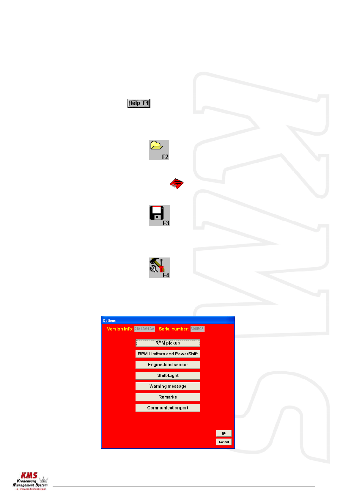
3.2.4 Function key F4 .................................................................6
3.2.4.1 RPM pickup .................................................................7
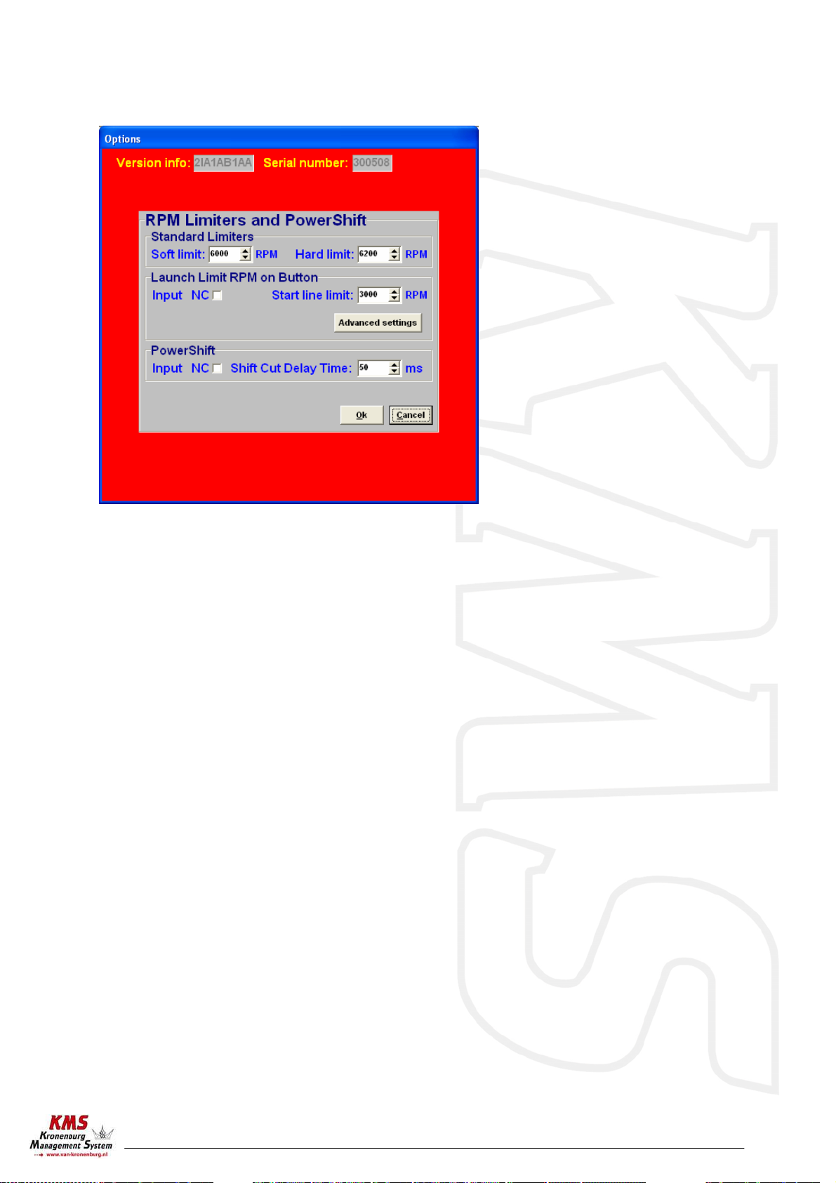
3.2.4.2 RPM Limiters and Powershift ............................................8
3.2.4.3 Engine-load sensor ........................................................9
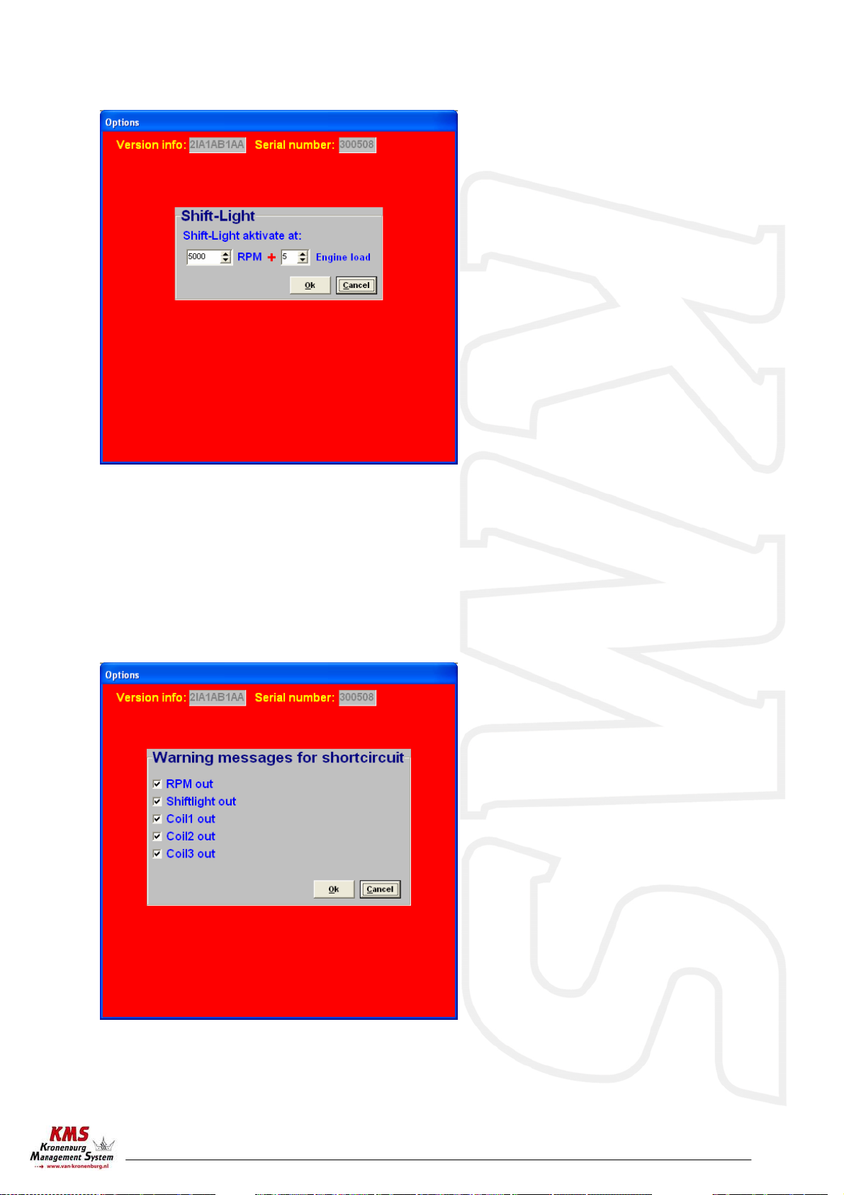
3.2.4.4 Shift-Light................................................................. 10
3.2.4.5 Warning message ........................................................ 10
3.2.4.6 Remarks................................................................... 11
3.2.4.7 Communicationport ..................................................... 11
3.2.5 Function key F6 ............................................................... 12
3.2.6 Function key F7 ............................................................... 12
3.2.7 Function key F10.............................................................. 13
3.3 The communication bar..........................................................14
4Programming.............................................................................15
4.1 Manual changing ...................................................................15
4.2 Bar charts ...........................................................................15
5Hardware installation .................................................................16
5.1 Fitting the ECU.....................................................................16
5.2 Connecting the communication cable.........................................16
6Fault tracing.............................................................................17
7Specifications............................................................................18
8Wiring Diagrams ........................................................................19
9Wiring examples ........................................................................21

KMS IB/IA23 manual
Version 3.01 3
1KMS (Kronenburg Management System)
This management system can be used as an independent ignition system for virtually all types of
Otto engine (engines in which the fuel mix is ignited via a spark plug).
This system provides the opportunity to give the desired spark timing at any running condition, in
order to achieve maximum torque and fuel efficiency at any rpm and load. This system also contains
options as; shift-light, RPM-limiters, launch control and powershift.
The set-up of the system software is kept as clear and simple as possible, so that even people with
little computer experience will be able to use this system. Working with the software is simple, but
if the settings are incorrectly configured, there is a serious risk of engine damage. We recommend
you leave the programming to specialists.

KMS IB/IA23 manual
Version 3.01 4
2Software installation
The software is supplied together with the system, on a CD-ROM. Installing the software is very
simple. The CD-ROM carries the KMS installation program, which launches automatically when the
CD is inserted.
Once installed, the program is set to work via communication port COM1. If this port is already
being used or not available, another communication port can be used. For the procedure to change
the communication port, see 3.2.4.6.

KMS IB/IA23 manual
Version 3.01 5
3KMS software
When the program is started, the main screen will appear, which is composed of three parts:
- The ignition characteristic diagram
- The function bar
- The communication bar
The following sections describe the possibilities and functions of the system.
3.1 The ignition characteristic diagram
The spreadsheet is a two-dimensional
diagram showing engine speed against
engine load.
The engine speed range stretches from
500 rpm to 20,000 rpm.
The engine load range is sub-divided into
16 boxes dividing the range that has been
set for the engine load sensor.
The rows and columns are shown in
graphs (in the form of bar charts), when
the left mouse button is clicked on an
engine speed or a load value. For further
information, see section 4.2.
In the ignition spreadsheet, figures can
be entered that indicate the ignition
advance angle in degrees of crankshaft
rotation. This means that for any engine
speed and engine load, the desired
ignition moment can be entered.

KMS IB/IA23 manual
Version 3.01 6
3.2 The function bar
The vertical bar on the right-hand side of the screen shows several function keys, which can be
activated using the mouse arrow or the relevant function keys on the keyboard. An explanation on
the different function keys is given in the following sections.
3.2.1 Function key F1
This function key gives access to the manual in Acrobat reader. Acrobat reader 3.0 or higher is
required. Acrobat reader 5.0 can be found on the installation CD-ROM.
3.2.2 Function key F2
This function key enables a previously saved file to be retrieved from the hard disk, floppy, CD-ROM
etc. The files can be recognised by a red floppy icon and by the extension .i0*
3.2.3 Function key F3
This function key is used to save modified files.
The names of these files automatically receive the extension .i03
3.2.4 Function key F4
When this function key is activated, a menu will appear on the screen, which gives the option of
several settings.
The options will be explained in the following sections.

KMS IB/IA23 manual
Version 3.01 7
3.2.4.1 RPM pickup
In this menu, the settings for the crankshaft signal, the type of ignition and the injection frequency
can be entered.
RPM Range: By clicking on the function you can set the rpm range for the main parameter maps.
Crank type: The engine speed signal should be obtained from an inductive sensor in combination
with a cog that matches one of the types shown in the 'Crank type' drop-down.
Reference point: The reference point (the position of the piston at the moment the first tooth
after the missing tooth/teeth passes the sensor) of the cog is between 0 and
180 degrees before TDC. The 6+1 cog (delphi system) is an exception to this
rule. The correct place for it is explained in the diagram shown in Appendix
1.
Number of cylinders: The number of cylinders of the engine can be filled in here. If the engine has
six cylinders, the 60-2, 36-2 or 36-1 cogs are the only ones that can be used.
Firing tooth under 500 rpm: This is for setting the number of teeth before TDC at which an
ignition impulse is given (under 500 rpm). Keep this number as low
as possible to prevent backfiring when the engine is started. For
engines with a high compression ratio do not set this to a number
higher than 1.
Coil on time: A coil should be charged before every discharge (plug spark). The coil charging time
is indicated in milliseconds. It should normally be 3.0 to 3.5 milliseconds. Longer
coil charging leads to unnecessarily high power consumption and heat development,
shortening the service life of the coil.
Dis coil: The choice is between dis coil and single coil control (rotor and distributor cap).
Ticking the box selects dis coil mode.

KMS IB/IA23 manual
Version 3.01 8
3.2.4.2 RPM Limiters and Powershift
This menu can be used to set various speed limiters and PowerShift.
The standard limiters include a soft and a hard limiter. The soft limiter stops ignition partially so
that power is lost. The hard limiter switches off ignition completely.
Under Launch limit an extra limiter can be set, which is activated, for instance, by a button.
Depending on the type of button, NC (normally closed) or NO (normally open), 'Input NC' will have to
be ticked or not. If the NO type is used, do not tick the box. 'Advanced settings' gives the possibility
of setting the ignition moment for several engine speeds at a maximum of 54 degrees after TDC
(retarded ignition is indicated by a negative number). This enables a high boost pressure to be built
up in turbocharged engines without further increasing the engine speed. Should the engine speed
increase in spite of ‘retarded ignition’, the extra limiter will intervene by stopping ignition and
injection.
Warning: When ignition-advance is applied, the temperature of the exhaust gasses may rise so
high that the exhaust valves, exhaust manifold and turbocharger are damaged. We recommend
you do not activate this function for longer than a few seconds!
PowerShift is a function that can be used for changing gear in sequential gearboxes. A switch on
the gearbox enables the engine output to be briefly interrupted, so that a gear change can be made
with the throttle valve fully open. This minimises the duration of gear-changing. The duration of the
interruption can be set to a maximum of 200 milliseconds.
Depending on the type of switch, the 'NC' box should be ticked.

KMS IB/IA23 manual
Version 3.01 9
3.2.4.3 Engine-load sensor
The engine load sensor connected to the system will have to be calibrated.
The range within which the sensor operates can be set here. A load sensor issues a voltage of 0 to
5V. The range is divided into 8 bits (256 steps). In practice a load sensor does not run through its
full range. For this reason, the upper and lower limits must be set, so that the 16 columns in the
spreadsheets can be best utilised.
There are two ways of calibrating the load sensor:
1) Automatic calibration
2) Manual calibration
When a throttle valve potentiometer is used, it is easy to opt for automatic calibration. Select
'Automatic cal.' and then keep the throttle valve in rest position, pressing OK.
Then turn the throttle valve to full load and press OK again.
The minimum and maximum values of the throttle
positions will now be shown.
A warning will appear if automatic calibration
cannot be finished correctly. For possible causes,
see 'Fault tracing'.
When a map sensor or an air mass sensor is used,
automatic calibration is not easy, because the
minimum and maximum output signals of the sensor are not known before the engine has run. We
recommend filling in the figures by hand, making sure that the output signal of the sensor under any
engine operating condition is between the two figures set. Tip: make the minimum value 15 and the
maximum value 250.

KMS IB/IA23 manual
Version 3.01 10
3.2.4.4 Shift-Light
This menu enables a shift light to be activated at a certain engine speed or engine load. So an extra
output can be activated, providing an ground-switching output directly (up to 15 watts) or via a
relay.
3.2.4.5 Warning message
In this option menu you can select the warning messages the ECU software must give when the
connections are short-circuit.

KMS IB/IA23 manual
Version 3.01 11
3.2.4.6 Remarks
Available space for making notes, for instance engine specifications.
3.2.4.7 Communicationport
Select the required communication port and save using the
'Save' button.
Select the required communication
port and save using the 'Save' button.
The FA23 system is based on Serial
port communication.
Depending on your laptop/desktop
system your communication port will
be selected for you. You can see this
on your computer in the hardware
profile. For desktops/laptops with a
serial port it is mostly COM1.
In this example on the left (startÆcontrol panelÆsystemÆdevice
manager) you can see that the USB-to-serial connection has set to COM 7.
When the desktop/laptop has no serial port, a usb-to-serial converter is
necessary.
(make sure that USB serial convertor will be dedicated to a COM
connection between 1 and 8. If this number exceeds 8, sometimes the
convertor will not function properly. At the advanced settings of the COM
port you can change the port number of your convertor to a number
between 1 and 8).

KMS IB/IA23 manual
Version 3.01 12
3.2.5 Function key F6
After this function key has been clicked and one or more boxes in the diagram have been selected,
an edit menu will appear. In this edit menu the values of the selected boxes can be changed. The
choice is between a change in terms of percentage, a change to a fixed value, and horizontal or
vertical interpolation. Horizontal or vertical interpolation is only possible if three or more boxes
have been selected in the diagram. With these functions, the values (horizontal or vertical)
between the outermost selected boxes will be interpolated.
3.2.6 Function key F7
When data is changed or downloaded to the system, the screen will show
the text 'DATA IS NOT LOCKED !!!'. At the same time, the silver-colour bar
of the diagram will change to a yellow colour. This is to indicate that the
changes have not yet been saved. Save the changes by pressing the F7
function key
When the box is clicked, the changes will be saved. If saving is
successful, the box will automatically change to . Once again, if
UNLOCKED is not clicked after the program has been changed, the changes
in the system will be lost when the power supply to the system is broken

KMS IB/IA23 manual
Version 3.01 13
3.2.7 Function key F10
Function key F10 offers the choice of working off-line or on-line. It switches communication with
the system on or off. Communication will also be stopped when the power supply to the system is
broken. If there is no communication, a red bar will appear at the bottom of the screen. To resume
the communication with the system, function key F10 should be pressed. A menu will appear
offering a choice between loading the file on the PC to the system and loading the file in the system
to the PC. There will still be the possibility of breaking the communication again.
Make sure that the battery of the vehicle supplies more then 10 Volts. If the battery doesn’t exceed
10 Volts the changes you made to the ECU will not be saved.
Tip: On vehicles with an ignition lock switched in such a way
that the power supply to the system is shortly cut off when
the engine is started, always download the data from the PC
to the system (as in the PC the modified data will not get lost
when the power supply to the system is broken). This is of
course only necessary if the data has not been saved to the
system.

KMS IB/IA23 manual
Version 3.01 14
3.3 The communication bar
The horizontal bar at the bottom of the screen is the communication bar. If the system is connected
to the COM port of the PC and the power supply to the system is on, function key F10 can be used to
activate the communication.
There are three check lights in the communication bar, which indicate the status of the relevant
outputs.
The following readings will be shown:
- Engine speed
- Advanced ignition angle
- Engine load
These readings can be used to check whether the right sensors are being used and all settings are
correct.

KMS IB/IA23 manual
Version 3.01 15
4Programming
Before programming is started, all connections and sensors must be checked. Look at the
communication bar to check the sensors for correct functioning and setting.
If everything is in good working order, the programming of the diagrams can be started.
There are three ways of changing the values shown in the diagrams:
1) Filling in the data manually, using the F6 edit menu
2) Changing bar charts using arrow keys
4.1 Manual changing
The value of a selected box can be changed manually. If the F6 button is on, an edit menu will
appear which offers several ways to change the selected values (see 3.2.5.).
4.2 Bar charts
The columns or rows of the diagrams can also be shown in the form of bar charts. The bar charts
will appear when an engine speed or engine load value is clicked. If an engine speed is clicked, a
bar chart will appear showing all the values related to that engine speed.
If an engine load value is clicked, a bar chart will appear showing all the values related to that
engine load value. Access to the bar charts can also be obtained by pressing the ALT + C keys or the
ALT + R keys simultaneously. The thin yellow line in the graphs of the injection diagram indicates
the maximum duration of injection for the engine speed concerned.
It is also possible to modify the diagram values in the bar charts by using the arrow keys, or the
arrow keys in combination with the Ctrl or Alt key. The left/right arrow keys can be used to move
through a column or row. When the upward or downward arrow key is used, the value will go up or
down 0.10 with each touch of the key. If the Alt key is pressed simultaneously, the value will
change 0.01 per touch and if instead of the Alt key the Ctrl key is pressed, the value will change
1.00 per touch.
When the engine is running, the space bar can be touched to go automatically to the relevant value
in the bar chart (matching the current situation of the engine), even when this value is at another
engine speed or engine load.
To go to another engine speed or engine load, use the Page Up / Page Down keys.

KMS IB/IA23 manual
Version 3.01 16
5Hardware installation
To guarantee that the system functions properly, it is of utmost importance to adhere to the
instructions given below.
5.1 Fitting the ECU
It is important that the ECU should be fitted in a dry and not too hot place.
5.2 Connecting the communication cable
Attached to the included wiring loom of your KMS IB/IA23 system is a serial port. You can use this
communication for you desktop/laptop and make a connection with the KMS Ignition software.
Warning: Be sure what kind of ignition coil you have. Is this a coil without
amplifier, use the thicker wires of the ECU. If you have a coil with
amplifier it’s important to use the thinner connector wires.

KMS IB/IA23 manual
Version 3.01 17
6Fault tracing
Fault Possible cause Solution
No communication between ECU
and PC - No power supply to the system
- Cable connected to wrong COM
port (standard is COM1)
- Switch the contact on or check the
fuse
- Connect cable to COM1 or select
another COM port
Engine does not start - No engine speed signal
- Crank Type set is not correct
- Check the sensor and wiring
- See section 3.2.4.1.
Auto calibration gives message
'warning range too small'
Auto calibration gives message
'warning signal reversed'
Auto calibration gives message
'engine load sensor not
connected'
- Sensor range too small or
potentiometer connected
incorrectly
- Throttle valve potentiometer
turns in the wrong direction
- The engine load sensor signal
does not change
- Interruption in potentiometer
signal wiring
or potentiometer does not turn
when the throttle valve is opened
- Check the wiring
- Fill in the values of the engine
load sensor manually
- Interchange the earth and 5V
wiring of the potentiometer
Only coils 1-4 give ignition - Dis coil box not ticked - See paragraph 3.2.4.1.

KMS IB/IA23 manual
Version 3.01 18
7Specifications
Minimum system requirements:
Windows 95,98,2000,NT,ME or XP
Internal memory 32Mb
Screen resolution 800x600
Standard RS232C port
CD-ROM station (software is also available on diskette)
Acrobat reader 3.0 or higher (Acrobat reader 5.0 is included on the CD-ROM supplied)
ECU specifications:
Supply voltage 8.5 - 16 volts
Power consumption 250mA at 12 volts
5 volt supply to sensors can have maximum 100mA
Inputs:
Inputs are protected up to 50 volts
Input for engine load is suitable for potentiometers, air mass meters and map sensors with an
output between 0 and 5 volts.
Outputs:
Shift-lamp output max. 1 amp at 12 volts per output
Dimensions:
KMS IA23
LxWxH: 85 x 85 x 40 mm
Weight: 280 gram
KMS IB
LxWxH: 111 x 67 x 22 mm
Weight: 200 gram

KMS IB/IA23 manual
Version 3.01 19
8Wiring Diagrams
standard colors KMS IA23 wiring-loom
PIN nr. color 0,5mm² 0,75mm² function details
1 purple * Coil 3 (amplified) For use directly on -coil
2 purple * Coil 3 Only used to trigger an coil driver
3 red/black * Tacho output Low voltage RPM signal
4 blue * Shiftlight Activates when connected to ground
5 white/red * Analog aux input Not yet available
6 black * ECU ground Make permanent connection!
7 red * ECU +12V supply Use 5-10 Amp. Fuse on ignition key
8 green * communication
9 green * Coil 2 (amplified) For use directly on -coil
10 green * Coil 2 Only used to trigger an coil driver
11 orange/black * Crank sensor signal (hall sensor)
12 red * Crank sensor signal Twisted with blue (inductive sensor)
13 grey * Load signal For example TPS/MAP/MAF
14 black * Load signal ground (TPS/MAP) For example TPS/MAP/MAF
15 red * communication
16 orange * Coil 1 (amplified) For use directly on -coil
17 brown * Ground ignition drivers Connect permanent when using amplified outputs
18 orange * Coil 1 Only used to trigger an coil driver
19 blue * Crank sensor ground Twisted with red
20 yellow * Load-sensor +5V supply For example TPS/MAP/MAF
21 green/red * Powershift Activates when connected to ground
22 yelow/black * Launch control Activates when connected to ground
23 black * communication

KMS IB/IA23 manual
Version 3.01 20
standard colors KMS IB breakout-loom
colo
r
0,5mm² 0,75mm² function details
white/red * Analog aux input Not yet available
red/black * Tacho output Low voltage RPM signal
purple * Coil 3 Only used to trigger an coil driver
green * Coil 2 Only used to trigger an coil driver
orange * Coil 1 Only used to trigger an coil driver
purple * Coil 3 (amplified) For use directly on -coil
green * Coil 2 (amplified) For use directly on -coil
orange * Coil 1 (amplified) For use directly on -coil
brown * Ground amplified internal outputs Connect permanent when using amplified outputs
red * ECU +12V supply Use 5-10 Amp. Fuse on ignition key
yellow * Load-sensor +5V supply For example TPS/MAP/MAF
grey * Load signal For example TPS/MAP/MAF
black * Load signal ground (TPS/MAP) For example TPS/MAP/MAF
black * Extra ground For connecting powershift/launch control
blue * Crank sensor ground Twisted with red
red * Crank sensor signal Twisted with blue (inductive sensor)
orange/black * Crank sensor signal (hall sensor)
yelow/black * Launch control Activates when connected to ground
green/red * Powershift Activates when connected to ground
blue * Shiftlight Activates when connected to ground
black * ECU ground Make permanent connection!
Table of contents
Other KMS Automobile Accessories manuals