KMS MA5 User manual

MA5 Manual V5.1

KMS MA-5 manual
Version 5.1 2
Contents
1KMS (Kronenburg Management Systems).................................................................................................................... 3
2Software installation....................................................................................................................................................... 5
3KMS software.................................................................................................................................................................. 6
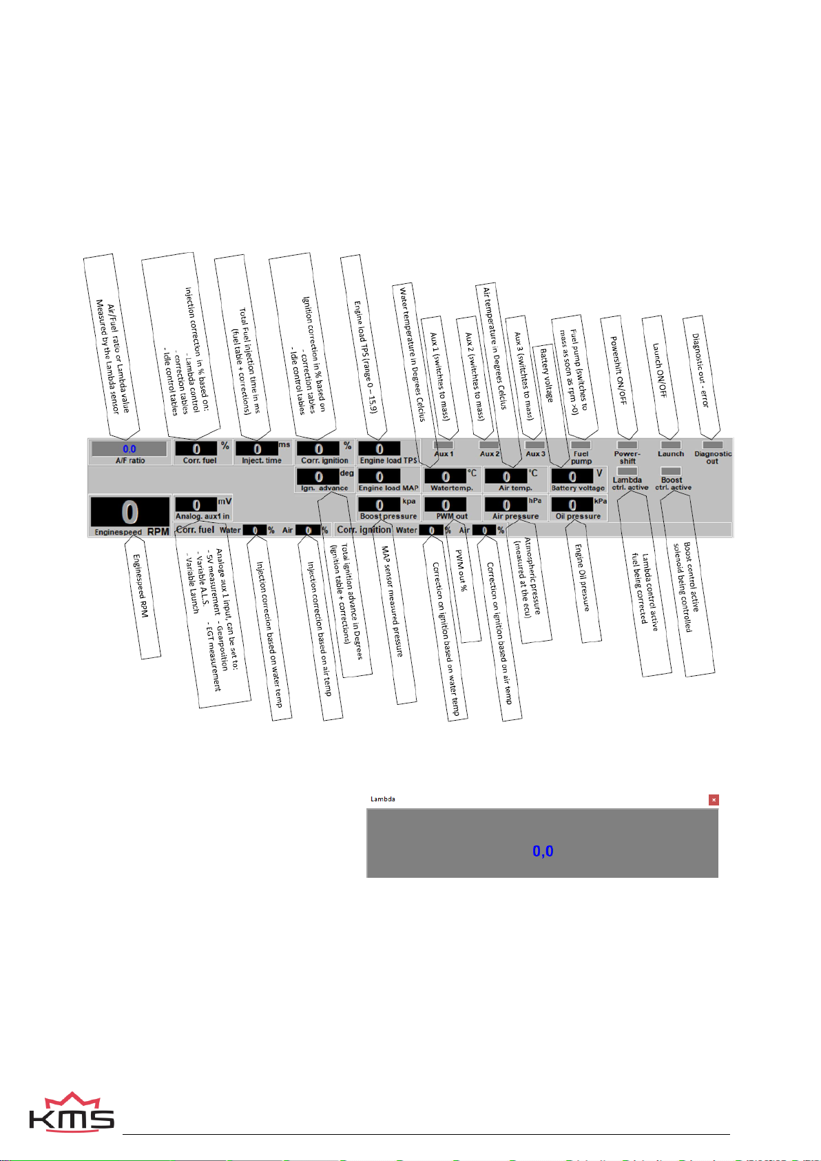
3.1 Main Screen.......................................................................................................................................................... 6
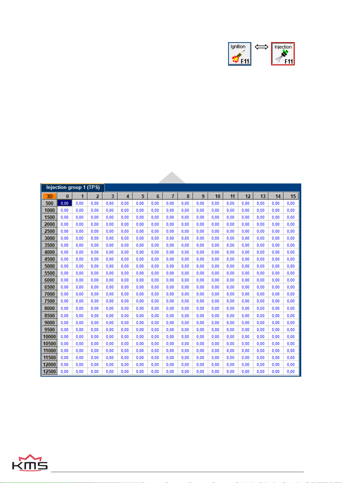
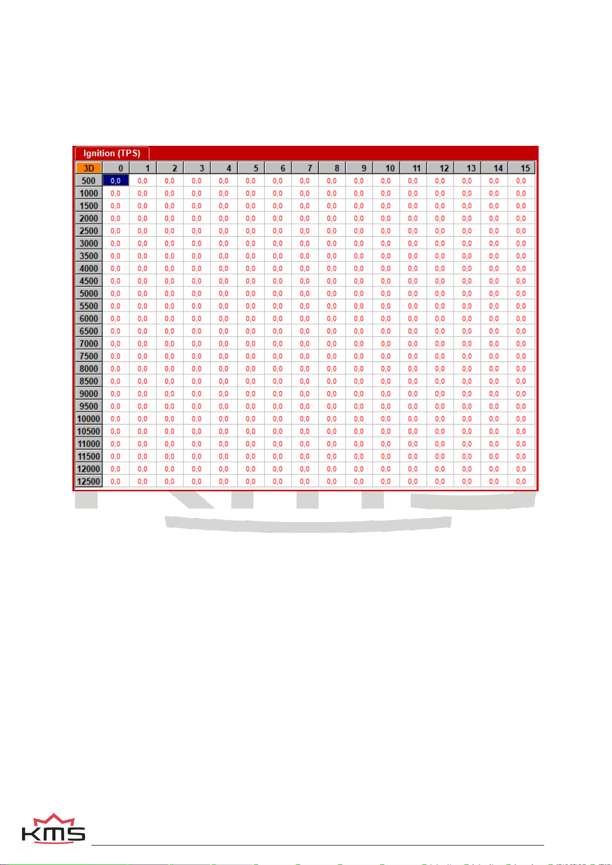
3.1.1 The Injection or Ignition table............................................................................................................................ 7
3.1.1.1 The injection characteristic diagram ....................................................................................................... 7
3.1.1.2 The ignition characteristic diagram......................................................................................................... 8
3.1.2 The communication bar .................................................................................................................................... 9
3.1.3 The function bar................................................................................................................................................ 9
3.2 Open file ............................................................................................................................................................. 10
3.3Save file.............................................................................................................................................................. 10
3.4 Options............................................................................................................................................................... 10
3.4.1 Options........................................................................................................................................................... 11
3.4.1.1 RPM pickup.......................................................................................................................................... 12
3.4.1.2 RPM limiters and PowerShift................................................................................................................ 16
3.4.1.3 Engine load sensor............................................................................................................................... 18
3.4.1.4 Start-up................................................................................................................................................ 22
3.4.1.5 Throttle pump effect ............................................................................................................................. 22
3.4.1.6 Interpol. to limits and Fuel cut............................................................................................................... 23
3.4.1.7 Hardware configuration ........................................................................................................................ 24
3.4.1.8 Lambda-control.................................................................................................................................... 25
3.4.1.9 Boost control........................................................................................................................................ 32
3.4.1.10 A.L.S.................................................................................................................................................... 37
3.4.1.11 AUX 1 .................................................................................................................................................. 38
3.4.1.12 AUX 2 .................................................................................................................................................. 38
3.4.1.13 AUX 3 ................................................................................................................................................. 38
3.4.1.14 External Dashboard............................................................................................................................. 39
3.4.1.15 Remarks.............................................................................................................................................. 40
3.4.1.16 Communication port............................................................................................................................. 40
3.4.2 Output test...................................................................................................................................................... 41
3.4.3 Crankshaft sensor test.................................................................................................................................... 41
3.4.4 Motor + system diagnostics ............................................................................................................................ 42
3.4.5 Change user access level............................................................................................................................... 45
3.5 Correction tables................................................................................................................................................ 46
3.6 Idle control ......................................................................................................................................................... 48
3.7 Up / down load function..................................................................................................................................... 49
3.8 Lambda function................................................................................................................................................ 49
3.9 Interpolation function ........................................................................................................................................ 49
3.10 Online / Offline ................................................................................................................................................... 50
3.11 Switch Injection/Ignition.................................................................................................................................... 51
3.12 Help..................................................................................................................................................................... 51
3.13 Communicationport........................................................................................................................................... 51
3.14 Shortcuts............................................................................................................................................................ 51
4Programming................................................................................................................................................................ 52
4.1 Manual changing boxes..................................................................................................................................... 52
4.2 Bar charts adjustment ....................................................................................................................................... 52
4.3 3D graph changing............................................................................................................................................. 53
4.4 Loading correction maps .................................................................................................................................. 53
5Hardware installation ................................................................................................................................................... 54
5.1 ECU specifications............................................................................................................................................. 55
6Troubleshooting ........................................................................................................................................................... 56
7Specifications............................................................................................................................................................... 59
8Appendix 1: Trigger pattern drawings......................................................................................................................... 60

KMS MA-5 manual
Version 5.1 3
1 KMS (Kronenburg Management Systems)
Kronenburg Management Systems (KMS) is a complete line of programmable engine control units
(ECU), that offers you an extremely reliable and user-friendly system at a very competitive price. It
gives you the possibility to manage all turbo and naturally aspirated Otto engines (engines in which
the fuel mix is ignited via a spark plug) up to 12 cylinders.
An engine control unit is a type of electronic control unit that determines the amount of fuel, ignition
timing and their parameters which is needed to keep an internal combustion engine running. It does
this by reading values from multidimensional maps which contain values calculated by sensor devices
monitoring the engine.
The programmable KMS ECU doesn’t not have a fixed behaviour, but can be (re)programmed by the
user. Programmable ECU’s are required when a significant modification has been made to a vehicle's
engine. For example, adding a turbocharger, changing the camshaft profile or a conversion to an
alternative fuel. In these situations, a programmable KMS ECU can be wired in. The KMS ECU’s can
be programmed/mapped with a laptop connected using a USB cable, while the engine is running.
The programmable ECU controls the amount of fuel to be injected into and ignition moment for each
cylinder. This varies depending on the engine's RPM and the position of the gas pedal and/or the
Manifold Absolute Pressure (MAP). This can be adjusted by bringing up a spreadsheet page on the
laptop where each cell represents an intersection between a specific RPM value and a throttle
position. In this cell a value corresponding to the amount of fuel injected can be entered. This
spreadsheet is referred to as a fuel table or fuel map. The same way the ignition spreadsheet can be
setup.
By modifying these values while monitoring the exhaust gas composition (best way is using a wide
band lambda sensor) you can see if the engine runs rich or lean. This way you can find the optimal
amount of fuel and optimal ignition moment needed for all possible combinations of RPM and throttle
position/manifold absolute pressure. This process can be best carried out at a dynamometer, giving a
controlled environment (without influence from outside) to work in. An engine or chassis dynamometer
gives a more precise calibration for your (racing) applications.
The KMS MA5 ECU offers a complete self learning air fuel ratio control (lambda control) for most
common types of oxygen sensors (Wideband/narrow band).
In addition to lambda control, this management system also provides the following functions: load-
dependent boost pressure control, water injection control, (variable) launch control, power-shifting,
(variable) A.L.S, idle control, rpm limiters, engine diagnostics, canbus etc.
This management system can be used as an independent injection/ignition system for virtually all
types of Otto engine, but can also be used in combination with a standard engine management
system. It can take over the standard injection/ignition at any desired engine speed, boost pressure or
throttle valve position. Precise ignition and air/fuel mixture control leads to excellent drive- ability and
low fuel consumption.
We advise to read the manual completely before starting. The set-up of the system software is kept as
clear and simple as possible, so that even people with little computer experience will be able to use
this system. Working with the software is simple, but if the settings are incorrectly configured, there is
a serious risk of engine damage. In this manual there are warning signs and notes that need your
extra attention to bring this setup to a good end. We recommend you leave the programming to
specialists.

KMS MA-5 manual
Version 5.1 4
WARNING:
Disconnect the battery cables when you’re doing electrical work.
Disconnect the KMS ECU from the wiring harness connector when welding on the vehicle.
Make sure there are no fluid leaks and all connections are secured and/or tightened.
Wiring and fuel system components must be mounted away from heat sources or shielded if
necessary.
Do not use a batterybooster or a 24V charger. Do not reverse the polarity of the battery or the
charging unit. Do not change the battery with the engine running. The peak power supply could
severely damage the KMS ECU and other electrical devices.
Avoid open sparks and flames near flammable substances.
Do not use unsuppressed spark plugs and leads. They can cause electromagnetic interference.

KMS MA-5 manual
Version 5.1 5
2 Software installation
The KMS Motor management software can be found at the download section on our website:
kms.vankronenburg.nl/downloads
In case there is a firmware update for the MA5 available then you will need the KMS firmware
downloader, this can also be found on our download section:
kms.vankronenburg.nl/downloads
Once installed, the program is set to work via communication port COM1. If this port is already being
used or not available, another communication port can be used. For the procedure to change the
communication port, see Communicationport.
(USB connections have the most various numbers of communication ports, so make sure you’ve got
the communication port right. For settings and finding the right communication port see
Communicationport)

KMS MA-5 manual
Version 5.1 6
3 KMS software
3.1 Main Screen
When the program is started, the main screen will appear, which is composed of three parts:
The Injection table (can be switched to the Ignition table)
The function bar
The communication bar
These sections describe the possibilities and functions of the system.

KMS MA-5 manual
Version 5.1 7
3.1.1 The Injection or Ignition table
The part of the main screen consists of two spreadsheets (ignition and
injection) of which only one is visible at a time. To toggle between the
tables, use function key F11 or by pressing the Injection / Ignition key.
The spreadsheets are two-dimensional tables showing engine speed against engine load.
The engine speed range can stretch from 500 rpm to 20.000 rpm. Standard the screen stretches from
500 rpm to 12.500 rpm. This however can be changed (see RPM pickup). The RPM range is divided
over 25 boxes. The engine load range is sub-divided into 16 boxes dividing the range that has been
set for the engine load sensor. The rows and columns are shown in graphs (in the form of bar charts),
when the left mouse button is clicked on an engine speed or a load value. For further information, see
section Programming.
3.1.1.1 The injection characteristic diagram
In the injection characteristic diagram, figures can be entered that indicate the injector opening time
per injection in ms. This means that at any engine speed and any engine load, the desired quantity of
fuel can be injected.

KMS MA-5 manual
Version 5.1 8
3.1.1.2 The ignition characteristic diagram
In the ignition spreadsheet, figures can be entered that indicate the ignition advance (in crankshaft
degrees before TDC). This means that for any engine speed and any engine load, the desired ignition
moment can be entered.

KMS MA-5 manual
Version 5.1 9
3.1.2 The communication bar
The horizontal bar at the bottom of the screen is the communication bar. If the system is connected to
the COM or USB port of the PC and the power supply to the system is on, function key F10 can be
used to activate the communication.
There are nine check lights in the communication bar, which indicate the status of the relevant
outputs.
The following readings will show:
These readings can be used to check whether the right sensors are being used and all settings are
correct.
There is an option to get an enlarged
picture of the lambda sensor reading by
clicking on the display bar. An extra
reading window will appear at the top of
the screen.
3.1.3 The function bar
The vertical bar on the right-hand side of the screen shows several function keys, which can be
activated using the mouse arrow or the relevant function keys on the keyboard. An explanation on the
different function keys is given in the following sections.

KMS MA-5 manual
Version 5.1 10
3.2 Open file
This function key enables a previously saved file to be retrieved from the hard disk,
external hard drive, USB memory key, etc. The files can be recognized by a crown icon
MA5 files have the extension *.m06.
3.3 Save file
This function key is used to save modified files.
The names of these files automatically receive the extension.
MA5 files have the extension *.m06.
3.4 Options
When this function key is activated, a menu
will appear on the screen, which gives the option of several settings and tests.
The options will be explained in the following sections.

KMS MA-5 manual
Version 5.1 11
3.4.1 Options
If 'Options' is selected, a menu appears
which lists several possible settings. These
settings are described below.

KMS MA-5 manual
Version 5.1 12
3.4.1.1 RPM pickup
In this menu, the settings for the crankshaft
signal, the type of ignition and the injection
frequency can be entered.
RPM Range:
By clicking on the function you can set the rpm range for the main parameter maps (minimum rpm is
500 and maximum is 20.000).
Standard the 25 rows are divided over a rpm range 12.500 rpm (example see left figure below). If your
engine doesn’t make more than 6.500 rpm, you can devide the 25 rows over this 6.500 rpm (example
see right figure below). So the mapping will be more fine tuned for this engine rpm range.

KMS MA-5 manual
Version 5.1 13
Crank pickup: You can enable the crank pickup and set the references.
Here you can select if your connected sensor is hall or inductive.
Hall sensor: a current runs through a thin Hall-plate. When this plate is undergoing a magnetic field a
voltage arises between the two sides of the plate. When a tooth passes the plate the magnetic field
changes.
Inductive sensor: consists of coil around constantly magnet. The change in magnetic field generates a
current in the coil. When a tooth passes the coil with magnetic core the magnetic field changes. When
a tooth is approaching the signal gets stronger. When a tooth is passed the signal gets weaker.
Difference is the Hall sensor generates a Voltage and the inductive sensor generates a current.
TIP: Measure the resistance between two pins by using a multimeter. When sensor is inductive the
resistance should be between 0.5 kΩand 2 kΩ. When the sensor uses a 3 pole connecter there
should also be the resistance of 0.5 kΩ – 2 kΩ between two pins. The remaining pin is the shield of
the sensor cable. If resistance is not measurable the sensor will be likely a Hall effect sensor.
Warning:
Do not use unsuppressed spark plugs and leads. They can cause
electromagnetic interference.
Crank-type:
The rpm signal has to be delivered by an hall/inductive sensor using a rotating trigger pattern. The
individual pattern types are listed under the pulldown menu. Not all trigger patterns are compatible
with all engine types. Possible combinations are listed in this table. Some trigger patterns are shown in
Appendix 1: Trigger pattern drawings.
When using a 60-2 trigger pattern the maximum engine speed is limited to 12.500 rpm.
We have for example a 150mm 60-2 trigger wheel available on our webshop, KMS partnumber
KMI.01.602
When using a Hall-sensor, it is nescessary to use a convertor that will change the Hall-signal into an
inductive signal (exception below). The convertor has KAC.17.001.
Ref. point:
The reference point (the position of the piston at the moment the first tooth after the missing
tooth/teeth passes the sensor) of the crank pickup sensor can be set between 0 and 180 degrees
before TDC (for most engines recommended between 70-120degree). The position of the reference
point in the software must be checked. Mark the TDC on the crankshaft pulley or flywheel. Check with
a timing light the degrees when igniting on cylinder 1 in TDC with a static engine speed. If the ignition
advance set in the software deviates from the measurement with the timing light, than you have to
correct the reference point in the software.
TIP: set for the complete rpm-range the ignition advance map to 10 degrees. The ignition advance
read out on the software screen will be stable and doesn’t change when your engine speed varies a
bit.
For example your reference point set in the software is 90 degrees. The ignition advance 10 degrees
at 1000 rpm. Checking with the timing light on cylinder 1 gives you 5 degrees ignition advance. That’s
a deviation of 5 degrees which must be corrected on the reference point. The correct reference point
is 90 –5 = 85 degrees.

KMS MA-5 manual
Version 5.1 14
Warning:
When using wasted spark the read out on the timing light must be divided by
2. A timing light displaying 20 degrees advance with wasted spark is in reality
10 degrees ignition advance.
Coil on time:
A coil should be charged before every discharge (plug spark). The coil charging time is indicated in
ms. It should normally be 1.4 to 3.5 ms depending on the type of coil. Longer coil charging leads to
unnecessarily high power consumption and heat development, shortening the service life of the coil.
Warning:
The coils can only be operated via a driver circuit. If the computer is
connected to the coil directly, the ECU can get damaged beyond repair. Many
modern coils feature a built-in driver stage. However, if a coil without an
integrated driver stage is used, the separate KMS ignition driver module with
part number KAC.05.002 will be needed.
Dis-coil:
The choice is between dis-coil (wasted spark) and single coil control (rotor and distributor cap). If you
have a dis-coil (and also when using coil per plug wasted spark) the box has to be ticked.
If you use a rotor with distributor cap you need to deselect the Dis-coil tick box.
Tacho output:
Select the amount of cylinders of the vehicle. You can choose between 4, 5, 6, 8 and 10 cylinders.
For a 1, 2 choose 4 cylinders. For a 3 cylinder choose 6 cylinder.
Warning:
For adaptation to a 5, 8 or 10 cylinder configuration, ensure that the ‘No. of
cylinders’has been specified correctly before connecting the coils. If the coils
are connected with the numbers of cylinders incorrectly set, the coils (via
output 4 and 5) can get seriously damaged.

KMS MA-5 manual
Version 5.1 15
Firing tooth under 500 rpm:
This is for setting the number of teeth before TDC at which an ignition impulse is given (under 500
rpm). Keep this number as low as possible to prevent backfiring when the engine is started. For
engines with a high compression ratio it is recommended not to set this to a number higher than 1.
Injection in ‘x’stroke mode:
The injection frequency (x) can be set to:
2 times per crankshaft revolution (x = 1)
1 time per crankshaft revolution (x = 2)
1 time per two crankshaft revolutions (x = 4)
Normally, it is recommended to select the 4-stroke setting.

KMS MA-5 manual
Version 5.1 16
3.4.1.2 RPM limiters and PowerShift
Standard Limiters
This menu can be used to set various speed
limiters and Power Shift.
The standard limiters include a soft and a
hard limiter. The soft limiter stops ignition
partially so that power is lost. The hard limiter
switches off ignition completely.
For the KMS MA5 management system the
maximum rpm limiter is 20.000 rpm *
*: with a 60-2 crank trigger pattern the
maximum engine speed is limited to 12.500
rpm.
Launch Limit RPM on button
At launch limit an extra limiter (start line) can
be set which is activated, for instance, by a
button that connects pin 19 to the ground.
Depending on the type of button, NC
(normally closed) or NO (normally open),
'Input NC' will have to be ticked or not. If the
NO type is used (recommended) do not tick
the box. There is also the possibility to set an
extra launch limiter which makes it possible
to make the launch limiter variable between
these two rpm’s by connecting a
potentiometer signal to the analog aux input,
which can be configured for this function, see
Hardware configuration. The potentiometer
must have a range between 1 kΩ and 47 kΩ.
The 5V and ground for the potentiometer are
available from the
5V/ground sensor supply. The signal of the
potentiometer must be connected to the Analog Aux 1.
Advanced settings:
This can be used to build up boost pressure before start. 'Advanced settings' gives the possibility of
setting a fixed ignition moment (between 54 degrees before and 54 degrees after TDC. After TDC is
indicated by a negative number), fixed fuel enrichment and fixed PWM boost for several ascending
engine speeds. This enables a high boost pressure to be built up in turbocharged engines without
further increasing the engine speed. Additional fuel enrichment can be set when launch control is
activated, this is needed to cool the engine. During activation lambda-control is switched off. Should
the engine speed increase in spite of ‘ignition retard’, the startline limiter will intervene by stopping
ignition and injection. The boost pressure can also be limited during launch by setting the duty-cycle
(PWM-value) of the boost control-solenoid.

KMS MA-5 manual
Version 5.1 17
Warning:
When ignition retard is applied, the temperature of the exhaust gasses may
rise so high that the exhaust valves, exhaust manifold and turbocharger will
be damaged. We recommend you to activate this function for no longer than a
few seconds!
Powershift
Powershift is a function that can be used for changing gear in sequential gearboxes.
A switch on the gearbox shifter enables the engine output to be briefly interrupted, so that a gear
change can be made with the throttle valve fully open. This minimizes the duration of gear-change.
The duration of the interruption can be set to a maximum of 200 ms. Depending on the type of switch,
NO (recommended) or NC, the 'NC' box should be ticked. If the ‘use advance settings’control box is
selected, the ‘advanced settings’menu must be set.
Advanced settings:
In this menu you can adjust the shift time for
each gear. However, a position sensor must
be present on the transmission housing for
this purpose. In this menu, you can then
specify the ascending output voltages
corresponding to the various gears. This can
be set manually or automatically. The voltage
range is 0 to 5V.
Cut time: Here you can set the desired
injection cut time for each gear(change)
position. The injection will be interrupted for
the time set here.
Delay time: At the moment the Power-shift
switch is activated, it is often desirable to
have a short delay before the switch takes
effect. This is because some resistance is
required to build sufficient power for
sequential shifting (charasteristic of
sequential gearbox).

KMS MA-5 manual
Version 5.1 18
3.4.1.3 Engine load sensor
Two engine load sensors called ‘Engine load
1’(for TPS = throttle position sensor) and
‘Engine load 2’(for MAP = manifold absolute
pressure sensor) can be connected. Even a
MAF sensor (mass air flow meter) can be
connected (not recommended). Please note
that certain combinations will result in the
exclusion of some options.
The use of two load sensors for most N/A
and all turbo-charged engines is higly
recommended.
Some settings in the software are always
related to TPS and some to the MAP-sensor.
However there is the possibility to select on
which sensor (TPS, MAP, combination
TPS/MAP) the main load tables are linked to.
In the picture on the side you can see all the possible combinations.
The possible combinations are explained below.
Engine load 1 (Throttle Position Sensor)
All the load tables included lambda target are linked to TPS value.
This is normally used for N/A engines with throttle bodies.
Engine load 2 (MAP or MAF)
All the load tables included lambda target are linked to MAP or MAF value.
This is normally used for turbo/supercharged engines .
Engine load 1 (TPS) + Engine load 2 as Boost correction table
this function is not available for the MA5.
Engine load 1 (TPS) + Engine load 2 as Boost correction factor
The ignition load table and lambda target are linked to MAP value (the ignition table for a turbocharged
and supercharged engine should always be linked to MAP). The injection table however is linked to
TPS and works in combination with the boost correction factor to determine the main fuel injection
time.

KMS MA-5 manual
Version 5.1 19
TPS + MAP as boost correction factor
-150
-100
-50
0
50
100
150
200
250
300
350
0100 200 300
Manifold Absolute Pressure [kPa]
Enrichment [%]
Boost correction factor = 1.00
Boost correction factor = 1.25
Boost correction factor = 1.50
In the figure above, you can see an example of how different boost correction factors influence the
enrichment percentage and injection time. So if the injection time in the complete injection table is set
at 10 ms and correction factor set on 1.00 the injection time increases with 10ms/100kPa what results
in a injection time of 20 ms at 200 kPa (1 bar boost) and 30 ms at 300 kPa (2 bar boost). With the
correction factor set on 1.25 this is 1.25 x 10 ms = 12.5ms/100kPa and thus giving an injection time of
22,5 ms at 200 kPa (1 bar boost) and 35 ms at 300 kPa (2 bar boost). Unregarded the correction
factor the negative fuel enrichment (under 100 kPa) will always be at a 1:1 ratio.
So if engine runs on 50 kPa (0,5 bar vacuum) the injection value will be 50% of 10 ms = 5 ms.
TIP: Try to start the engine with the complete fuel map at the same injection time (4 - 12 ms
depending on the injector size) and the boost correction factor set on 1.25. Try to get the engine
running smooth with changing the complete fuel map (all cells at once) with positive or negative
percentage (using the edit menu). If lambda control is active and the engine is at normal operating
temperature you can start programming (the separated cells in) the fuel map with the boost pressure
(set) as low as possible. After the injection table is mapped at low boost, the next step is to raise the
boost level in steps to the desired boost pressure. Check your fuel correction again. Now don’t correct
the injection table with this percentage but correct your boost correction factor with this percentage.
Engine load 1 (TPS) + Engine load 2 as pressure compensation NA engines
All the load tables included lambda target and correction tables are linked to TPS value. The injection
tables are compensated for the manifold absolute pressure. Engines with standard manifolds often
have bypasses and/or solenoids for situations when extra air is needed. This extra air isn’t
compensated with fuel when only linking to TPS.
The injection table (TPS v RPM) gets corrected with 1% per 1 kPa of MAP pressure offset from 100
kPa. So if the injection time in the complete injection table is set at 10 ms, the injection time decreases
with 1ms/10kPa. What results in a injection time of 7.5 ms at 75 kPa. If the engine runs on 50 kPa (0.5
bar vacuum) the injection value will be 50% of 10 ms = 5 ms.
This is used for N/A engines.

KMS MA-5 manual
Version 5.1 20
Engine load sensor calibration:
The engine load sensor connected to the system will have to be calibrated.
The range within which the sensor operates can be set here. A load sensor issues a voltage of 0 to
5V. The range is divided into 8 bits (256 steps). In practice a load sensor does not run through its full
range. For this reason, the upper and lower limits must be set, so that the 16 columns in the
spreadsheets can be best utilized.
There are two ways of calibrating the load sensor:
Automatic calibration
Manual calibration
Automatic calibration. When a throttle valve potentiometer is used, it is easy to opt for automatic
calibration. Select 'Automatic cal.' and then keep the throttle valve in rest position, pressing OK.
Then turn the throttle valve to full load and press OK again.
The minimum and maximum values of the throttle positions will now be shown.
A warning will appear if automatic calibration cannot be finished correctly. For possible causes, see
'Troubleshooting'.
Manual calibration. When a map sensor or an air mass sensor is used, automatic calibration is not
easy, because the minimum and maximum output signals of the sensor are not known before the
engine has run. We recommend filling in the figures by hand, making sure that the output signal of the
sensor under any engine operating condition is between the two figures set.
Tip: first set the minimum value 15 and the maximum value 250. If you use a KMS 400 kpa Map
sensor there are recommended settings for the calibration on the datasheet of the sensor.
Not all load sensors emit signals that are linear with the engine load. For this reason the system offers
the possibility to choose between three load characteristics. This enables the upper/lower areas to be
made more sensitive or less sensitive.
The three load characteristics are linear, logarithmic and e-log and are explained in an overview on
below.
This manual suits for next models
1
Table of contents
Other KMS Automobile Accessories manuals
Popular Automobile Accessories manuals by other brands

Brodit
Brodit ProClip 804692 installation instructions

Atera
Atera Signo 045 012 User information

Toyota
Toyota handsfree communication user manual

Safe Fleet
Safe Fleet PRIME DESIGN VBR3-FT31B manual

IBASE Technology
IBASE Technology MPT-7000VSM user manual

FISCHER
FISCHER CrossLine L Original operating instructions