manuals.online logo
Brands
  1. Home
  2. •
  3. Brands
  4. •
  5. curt
  6. •
  7. Automobile Accessories
  8. •
  9. curt 52040 User manual

curt 52040 User manual

Other curt Automobile Accessories manuals

curt 16315 User manual

curt

curt 16315 User manual

curt 17510 User manual

curt

curt 17510 User manual

curt 13119 User manual

curt

curt 13119 User manual

curt 70130 User manual

curt

curt 70130 User manual

curt 16028 User manual

curt

curt 16028 User manual

curt R16 5TH User manual

curt

curt R16 5TH User manual

curt 70141 User manual

curt

curt 70141 User manual

curt 18112 User manual

curt

curt 18112 User manual

curt SWAY CONTROL User manual

curt

curt SWAY CONTROL User manual

curt 70118 User manual

curt

curt 70118 User manual

curt TruTrack 17601 User manual

curt

curt TruTrack 17601 User manual

curt 16994 User manual

curt

curt 16994 User manual

curt 57009 User manual

curt

curt 57009 User manual

curt CM 18031 User manual

curt

curt CM 18031 User manual

curt 13490 User manual

curt

curt 13490 User manual

curt 25470 User manual

curt

curt 25470 User manual

curt 18410 User manual

curt

curt 18410 User manual

curt 18087 User manual

curt

curt 18087 User manual

curt 13532 User manual

curt

curt 13532 User manual

curt 16993 User manual

curt

curt 16993 User manual

curt 58902 User manual

curt

curt 58902 User manual

curt 16055 User manual

curt

curt 16055 User manual

curt 11454 User manual

curt

curt 11454 User manual

curt 60607 User manual

curt

curt 60607 User manual

Popular Automobile Accessories manuals by other brands

Magneti Marelli AC161 Installation instruction

Magneti Marelli

Magneti Marelli AC161 Installation instruction

FDI uEZ GUI Start here

FDI

FDI uEZ GUI Start here

JCROffroad JT Install instructions

JCROffroad

JCROffroad JT Install instructions

Rostra VOXXElectronics 250-1930 owner's guide

Rostra

Rostra VOXXElectronics 250-1930 owner's guide

TOP VEHICLE TECH GR3FORD5 installation manual

TOP VEHICLE TECH

TOP VEHICLE TECH GR3FORD5 installation manual

Safe Fleet PRIME DESIGN AR-2000-BLK manual

Safe Fleet

Safe Fleet PRIME DESIGN AR-2000-BLK manual

Skoda Fabia Combi 5J Fitting instructions

Skoda

Skoda Fabia Combi 5J Fitting instructions

Camcar 40077 Al Mounting instructions

Camcar

Camcar 40077 Al Mounting instructions

Camcar 40089 AL Mounting instructions

Camcar

Camcar 40089 AL Mounting instructions

Impac Tradesman 2000 installation manual

Impac

Impac Tradesman 2000 installation manual

DVB OFFROAD BRSB-01 installation manual

DVB

DVB OFFROAD BRSB-01 installation manual

Safari Snorkel SS385HF installation guide

Safari Snorkel

Safari Snorkel SS385HF installation guide

ULTIMATE SPEED 279746 Assembly and Safety Advice

ULTIMATE SPEED

ULTIMATE SPEED 279746 Assembly and Safety Advice

SSV Works DF-F65 manual

SSV Works

SSV Works DF-F65 manual

ULTIMATE SPEED CARBON Assembly and Safety Advice

ULTIMATE SPEED

ULTIMATE SPEED CARBON Assembly and Safety Advice

Witter F174 Fitting instructions

Witter

Witter F174 Fitting instructions

WeatherTech No-Drill installation instructions

WeatherTech

WeatherTech No-Drill installation instructions

TAUBENREUTHER 1-336050 Installation instruction

TAUBENREUTHER

TAUBENREUTHER 1-336050 Installation instruction

manuals.online logo
manuals.online logoBrands
  • About & Mission
  • Contact us
  • Privacy Policy
  • Terms and Conditions

Copyright 2025 Manuals.Online. All Rights Reserved.

CURTMFG.COM •NEED ASSISTANCE? •8 7 7. 2 8 7. 8 6 3 4 •52040-INS-RB •PAGE 1
INSTALLATION MANUAL 52040
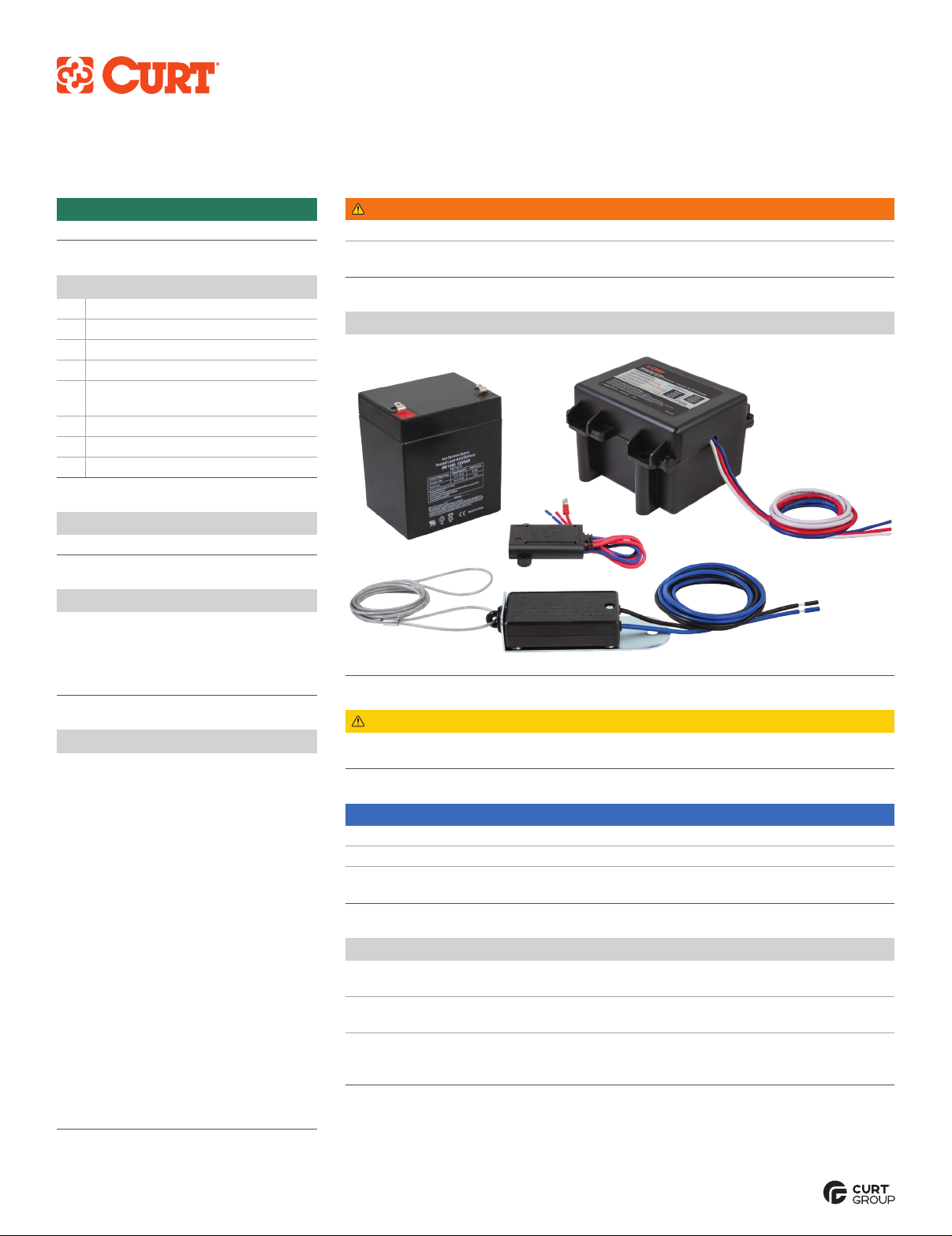
Product Photo
Level of Difficulty
Easy
WARNING
Never exceed the vehicle manufacturer's recommended towing capacity.
In order to avoid severe damage to the tow vehicle's electric brake controller, disconnect
the trailer connector from the tow vehicle prior to testing the breakaway system.
CAUTION
Do not attach the breakaway switch cable to
mounting hooks, trailer safety chains or the trailer ball.
Maintenance
Prior to each use, check the system's battery for operating voltage. Check that the breakaway
switch cables are not damaged from dragging on the ground and that they can move freely.
Check the breakaway system periodically to ensure proper and secure connections.
Open and / or short circuits may result in a no-brake situation.
Test the breakaway by pulling firmly on the cable of the breakaway switch.
The battery will activate the brakes. Note: Do not use this kit as a parking brake.
Ensure battery is charged prior to each use.
NOTICE
Before you begin installation, read all instructions thoroughly.
Proper tools will improve the quality of installation and reduce the time required.
To help prevent damage to the product or vehicle, refer to the specified
torque specifications when securing hardware during the installation process.
Parts List
1Breakaway switch
1Battery case
1Battery charger
1Battery, 12V 5Ah gel cell
4Self-tapping screw with
hex head washer, 1/4"-14 x 3"
4Flat washer, 5/16"
4Nylock nut, 5/16"
2U-bolt, 5/16"
Tools Required
None
Product Registration
CURT Group stands behind our products
with industry-leading warranties. Provide
feedback and help us to improve our
products by registering your purchase at:
warranty.curtgroup.com/surveys
Battery Charging
If the system measures voltage less
than 14V, the charging circuit will provide
maximum charging current to a 12V 5Ah
gel cell battery until the battery is fully
charged to 14V. During the operation,
the system provides a trickle charge
to maintain battery voltage.
When battery voltage is under 6V, relay
K1 will not activate when switch S1 is
activated and the whole tester circuit
will have no power and will not activate
either the green or red LED. This will
indicate a dead battery.
This breakaway kit is designed to activate
the trailer's electric brakes if the trailer
should disconnect while towing, bringing
the trailer to a safe stop. Breakaway kits
are required when towing trailers of
3,000 lbs. GTW or greater.
Note: Your trailer must be equipped with
electrical brakes in order to use this kit.
CURTMFG.COM •NEED ASSISTANCE? •8 7 7. 2 8 7. 8 6 3 4 •52040-INS-RB •PAGE 2
WIRING DIAGRAM
Breakaway
Switch
12V (+) - Black
12V (+) - Red
12V (-) - Black
12V (+) - Yellow
Trailer Brakes
Black
Brake Control
Output - Blue
Trailer Chassis
Ground
Trailer Chassis
Ground
Trailer
Connector
Push-to-Test
Panel
12V Trailer
Breakaway
Battery
Pos (+) (-) Neg
12V (-) - White
Step 2 - Wiring
Connect one of the black wires to the
breakaway battery's positive (+) terminal.
Splice the other black wire to the
blue wire leading to the trailer brakes.
Note: The blue wire should show 12V positive
when the vehicle brakes are applied.
Step 1 - Mounting
Position the breakaway switch on the tongue of the trailer so that it
allows the cable to reach the tow vehicle's trailer hitch safety chain
eyelets. This is critical for proper engagement of switch.
Identify a suitable mounting location and drill a 9/32" hole in the
trailer frame to mount the breakaway switch. Use the provided
hardware to mount the switch to the trailer Note: Use caution when
drilling the hole, making sure there are no wires or other objects
behind the drilling surface. Do not to over-tighten the bolt so the
breakaway switch can pivot.
Find a suitable location on the trailer frame to mount the battery case.
Mount in a location that it does not interfere with the switch's lanyard.
Step 3 - Wiring
Splice yellow wire on breakaway
box to trailer 12V auxiliary power lead.
Splice white wire of the breakaway box to the white
ground wire coming from the trailer side connector.
Prior to Towing
Prior to each use, check the system's battery for operating voltage.
Check that the breakaway switch cables are not damaged from
dragging on the ground and that they can move freely.
Check the breakaway system periodically to ensure proper and secure
connections. Open and / or short circuits may result in a no-brake situation.
Test the breakaway by pulling firmly on the cable of the breakaway
switch. The battery will activate the brakes. Note: Do not use this kit
as a parking brake. Ensure battery is charged prior to each use.
CAUTION
Do not attach the breakaway switch cable to
mounting hooks, trailer safety chains or the trailer ball.
WARNING
In order to avoid severe damage to the tow vehicle's electric brake
controller, disconnect the trailer connector from the tow vehicle prior
to testing the breakaway system.