manuals.online logo
Brands
  1. Home
  2. •
  3. Brands
  4. •
  5. Fortin
  6. •
  7. Automobile Accessories
  8. •
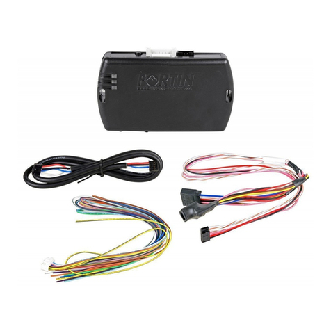
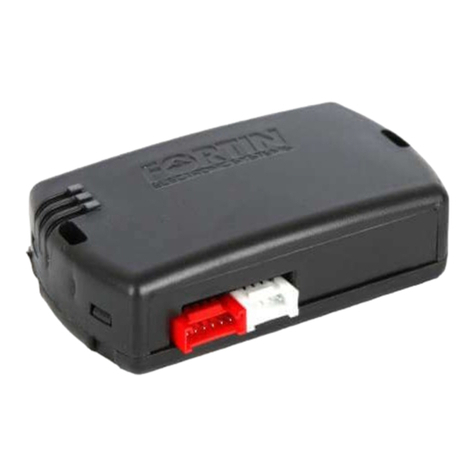
  9. Fortin EVO ONE THAR-ONE-HON6 User manual

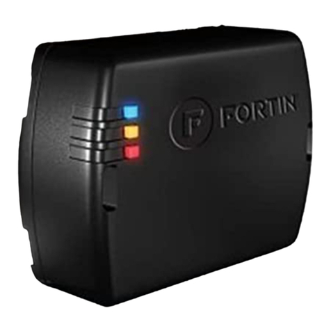
Fortin EVO ONE THAR-ONE-HON6 User manual

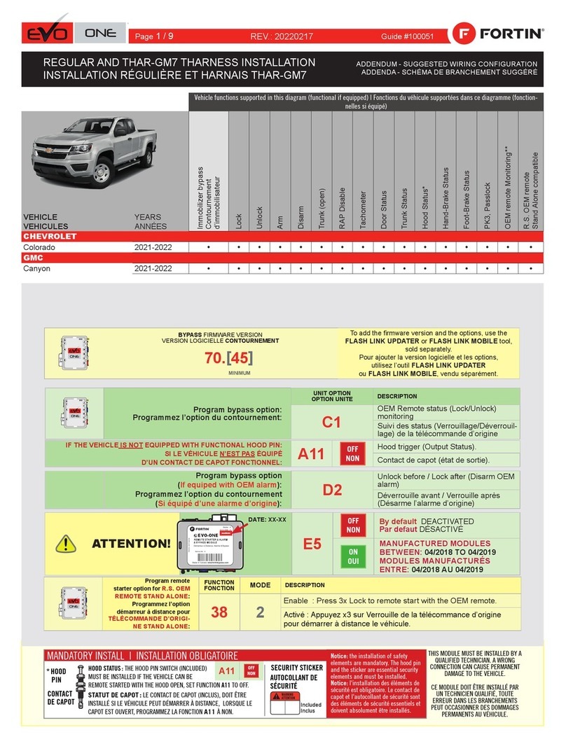
WARNING
ATTENTION
A11 OFF
NON
*
HOOD
PIN
HOOD STATUS : THE HOOD PIN SWITCH (INCLUDED)
MUST BE INSTALLED IF THE VEHICLE CAN BE
REMOTE STARTED WITH THE HOOD OPEN, SET FUNCTION A11 TO OFF.
CONTACT
DE CAPOT
SECURITY STICKER
AUTOCOLLANT DE
SÉCURITÉ
MANDATORY INSTALL | INSTALLATION OBLIGATOIRE Notice: the installation of safety
elements are mandatory. The hood pin
and the sticker are essential security
elements and must be installed.
Notice: l'installation des éléments de
sécurité est obligatoire. Le contact de
capot et l'autocollant de sécurité sont
des éléments de sécurité essentiels et
doivent absolument être installés.
THIS MODULE MUST BE INSTALLED BY A
QUALIFIED TECHNICIAN. A WRONG
CONNECTION CAN CAUSE PERMANENT
DAMAGE TO THE VEHICLE.
CE MODULE DOIT ÊTRE INSTALLÉ PAR
UN TECHNICIEN QUALIFIÉ, TOUTE
ERREUR DANS LES BRANCHEMENTS
PEUT OCCASIONNER DES DOMMAGES
PERMANENTS AU VÉHICULE.
STATUT DE CAPOT : LE CONTACT DE CAPOT (INCLUS), DOIT ÊTRE
INSTALLÉ SI LE VÉHICULE PEUT DÉMARRER À DISTANCE, LORSQUE LE
CAPOT EST OUVERT, PROGRAMMEZ LA FONCTION A11 À NON.
Included
Inclus
ONE REV.: 20220615
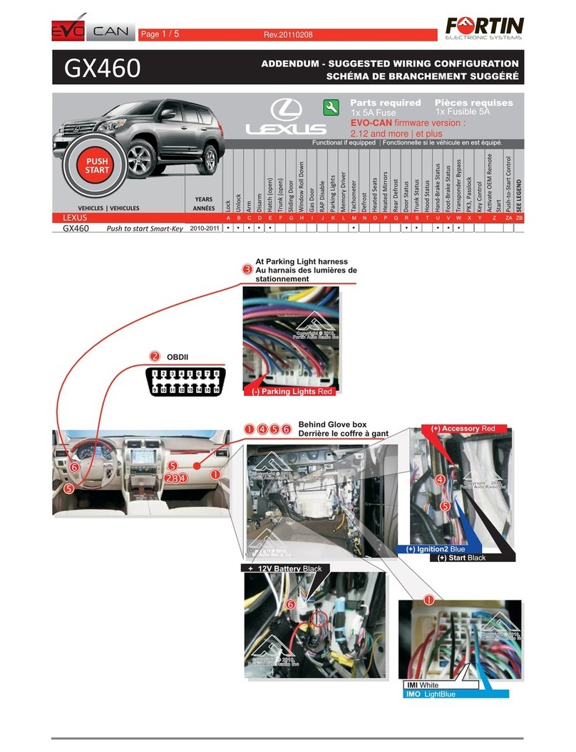
ADDENDUM - SUGGESTED WIRING CONFIGURATION
ADDENDA - SCHÉMA DE BRANCHEMENT SUGGÉRÉ
Vehicle functions supported in this diagram (functional if equipped) | Fonctions du véhicule
supportées dans ce diagramme (fonctionnelles si équipé)
VEHICLE
VEHICULES
YEARS
ANNÉES
Immobilizer Bypass
T-Harness available (sold
separately)
Harnais en T disponible
(vendu séparément)
Lock
Unlock
Arm
Disarm
Parking Lights
Trunk (open)
Aux.1 Heated seats
Tachometer
Door Status
Trunk Status
Hood Status*
Hand-Brake Status
Foot-Brake Status
Push-to-Start Control
OEM Remote Monitoring
R.S. OEM remote
Stand Alone compatible
ACURA
RDX
Push-to-Start
2019-2022
•
•
•
•
•
•
•
•
•
•
•
•
•
•
•
•
•
•
Guide # 81671
THAR-ONE-HON6 INSTALLATION WITHOUT TAKE OVER
INSTALLATION THAR-ONE-HON6 SANS PRISE EN CHARGE
Program bypass option:
Programmez l’option du contournement:
UNIT OPTION
OPTION UNITE DESCRIPTION
C1
OEM Remote status (Lock/Unlock)
monitoring
Suivi des status (Verrouillage/Déverrouil-
lage) de la télécommande d’origine
Program remote
starter option for R.S.
OEM REMOTE STAND
ALONE:
Programmez l’option
démarreur à distance
pour TÉLÉCOMMANDE
D’ORIGINE STAND
ALONE:
FUNCTION
FONCTION MODE DESCRIPTION
38 2
Enable
Press 3x Lock to remote start with the OEM remote.
Activé
Appuyez x3 sur Verrouille de la télécommance d’origine
pour démarrer à distance le véhicule.
D6 Push-to-Start
Push-to-Start
BYPASS FIRMWARE VERSION
VERSION LOGICIELLE CONTOURNEMENT
To add the rmware version and the options, use the
FLASH LINK UPDATER or FLASH LINK MOBILE tool,
sold separately.
Pour ajouter la version logicielle et les options,
utilisez l’outil FLASH LINK UPDATER
ou FLASH LINK MOBILE, vendu séparément.
73.[38]
HONDA/ACURA MINIMUM
Program bypass option
(If equiped with OEM alarm):
Programmez l’option du contournement
(Si équipé d’une alarme d’origine):
D2
Unlock before / Lock after (Disarm OEM
alarm)
Déverrouille avant / Verrouille après
(Désarme l’alarme d’origine)
Program bypass option
(If equipped with OEM alarm):
Programmez l’option du contournement
(Si équippé d’une alarme d’origine):
D3 Shutdown engine on door opening
Arrêt du moteur lors de l’ouverture d’une
porte
Program remote starter option for
HEATED SEATS:
Programmez l’option démarreur à
distance pour L’ACTIVATION SIÈGES
CHAUFFANTS:
39 2
Temperature option : AUX.1 activated at 5oC, 5 seconds after
remote started
Option de température: AUX.1 s’active à 5oC, 5 secondes après le
démarrage à distance
IF THE VEHICLE IS NOT EQUIPPED
WITH FUNCTIONAL HOOD PIN:
SI LE VÉHICULE N’EST PAS ÉQUIPÉ
D’UN CONTACT DE CAPOT FONCTIONNEL: A11 OFF
NON
Hood trigger (Output Status).
Contact de capot (état de sortie).
Page 1 / 8
This guide may change without notice. See www.fortin.ca for latest version.
Ce guide peut faire l’objet de changement sans préavis. Voir www.fortin.ca pour la récente version.
DESCRIPTION |DESCRIPTION
ATTENTION Avant de débrancher un module, un ordinateur ou une unité de contrôle d'un
véhicule: il faut toujours débrancher la borne négative de la batterie du
véhicule et après avoir rebrancher tous les connecteurs du module, de
l’ordinateur ou de l’unité de contrôle, rebranchez le pôle négatif de la batterie.
Before disconnecting a module, a computer or a control unit from a vehicle:
Always disconnect the negative terminal from the vehicle's battery and after
reconnecting all the connectors on the module, computer, or control unit,
reconnect the negative pole of the battery.
Vehicle battery
Batterie du véhicule
BCM
BCM Grey 40-PINS connector.
BCM Connecteur gris de 40-PINS.
BCM Tan 28-PINS connector.
BCM Connecteur Beige de 28-PINS.
BCM Black 32-PINS connector.
BCM Connecteur Noir de 32-PINS.
BCM Blue 36-PINS connector.
BCM Connecteur Bleu de 36-PINS.
BCM Blue 36-PINS connector.
BCM Connecteur Bleu de 36-PINS.
Page 2 / 8
Yellow In A1
Purple Out A2
Purple/White Out A3
Green Out A4
White Out A5
Orange Out A6
Orange/Black Out A7
Dk.Blue Out A8
Red/Blue In A9
Lt.Blue/Black In/Out A10
Black In A11
Pink Out A12
Yellow/Black Out A13
Brown/White In A14
Pink/Black In A15
Purple/Yellow In/Out A16
Green/White In/Out A17
Green/Red In/Out A18
White/Black Out A19
Lt.Blue In/Out A20
C5 Brown
C4 Gray/Black
C3 Gray
C2 Orange/Brown
C1 Orange/Green
D6 White/Red
D5 White/Blue
D4 White/Green
D3 Yellow/Red
D2 Yellow/Blue
D1 Yellow/Green
White Out E1
Orange Out E2
Red In E3
Black In E4
Pink In/Out E5
Yellow Out E6
This guide may change without notice. See www.fortin.ca for latest version.
Ce guide peut faire l’objet de changement sans préavis. Voir www.fortin.ca pour la récente version.
WIRING CONNECTION | GUIDE DE BRANCHEMENTS
(-) Hood pin
HOOD PIN
CONTACT CAPOT
CUT LOOP FOR AUTOMATIC
TRANSMISSION MODE.
COUPEZ LA BOUCLE POUR LE
MODE TRANSMISSION
AUTOMATIQUE.
A2
A3
A4
A5
A6
A7
A8
A9
A10
A11
A12
A13
A14
A15
A16
A17
A18
A19
A20
E1
E2
E3
E4
E5
E6
C5
C4
C3
C2
C1
D6
D5
D4
D3
D2
D1
A1
D4
D5
D6
C1
C2
C5
A20
A19
A18
A17
A14
A13
A11
A9
A8
A6
A4
A3
A2
A1
FEMALE T-HARNESS PLUG
CONNECTEUR FEMELLE
DU T-HARNAIS
28 PIN
MALE T-HARNESS PLUG
CONNECTEUR MÂLE
DU T-HARNAIS
36 PIN
MALE T-HARNESS PLUG
CONNECTEUR MÂLE
DU T-HARNAIS
32 PIN
MALE T-HARNESS PLUG
CONNECTEUR MÂLE
DU T-HARNAIS
MALE VEHICLE LT.GREY PLUG
CONNECTEUR MÂLE
DU VÉHICULE GRIS PÂLE
FEMALE T-HARNESS PLUG
CONNECTEUR FEMELLE
DU T-HARNAIS
MALE VEHICLE BLUE PLUG
CONNECTEUR BLEU MÂLE
DU VÉHICULE
FEMALE T-HARNESS PLUG
CONNECTEUR FEMELLE
DU T-HARNAIS
MALE VEHICLE BLACK PLUG
CONNECTEUR NOIR MÂLE
DU VÉHICULE
40 PIN
MALE T-HARNESS PLUG
CONNECTEUR MÂLE
DU T-HARNAIS
FEMALE T-HARNESS PLUG
CONNECTEUR FEMELLE
DU T-HARNAIS
MALE VEHICLE GREY PLUG
CONNECTEUR GRIS MÂLE
DU VÉHICULE
36 PIN
MALE T-HARNESS PLUG
CONNECTEUR MÂLE
DU T-HARNAIS
FEMALE T-HARNESS PLUG
CONNECTEUR FEMELLE
DU T-HARNAIS
MALE VEHICLE GREY PLUG
CONNECTEUR GRIS MÂLE
DU VÉHICULE
6 PIN CONN.
28 PIN GREY CONN.
36 PIN BLUE CONN.
32 PIN BLACK CONN.
36 PIN GREY CONN.
40 PIN GREY CONN.
5 PIN CONN.
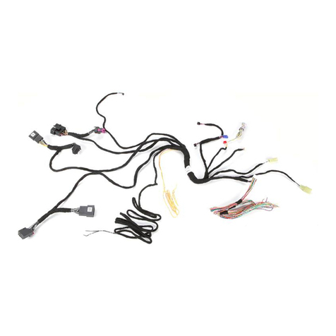
T-HARNESS - HARNAIS EN T THAR-ONE-HON6
NOT CONNECTED NON BRANCHÉ
ISOLATE
NOT CONNECTED
---------------------
ISOLER
NON BRANCHÉ
Page 3 / 8
ATTENTION
Fuse box.
Boîte à fusibles.
WITH THE EVO-ONE MODULE CONNECTED
TO THE T-HARNESS
Make sure that the vehicle starts normally
(start and stop) before proceeding with
programming:
AVEC LE MODULE EVO-ONE BRANCHÉ
AU HARNAIS EN T:
Assurez-vous que le véhicule démarre
normalement (démarrez et éteignez)
avant de procéder à la programmation:
1
2
3
Press the brake pedal. Appuyez sur la pédale de
frein.
Press the START/STOP
button with the key
inside the vehicle.
Appuyez 1 fois sur le
bouton démarrage avec la
clé à l’intérieur du
véhicule.
If the BCM or the battery
was unplugged and the
vehicle show the
message “START FAIL”,
Remove and put back
the fuse as shown
If the BCM or the
battery has been
disconnected, several
error messages will be
displayed until the
vehicle is driven.
Si le BCM ou la batterie a été
débraché et le véhicule indique
le message “DÉMARRAGE
NON AUTORISÉ”,
Retirer et remettre la fusible
comme indiqué.
Si le BCM ou la batterie ont
été débranchés, plusieurs
messages d'erreurs
s'afficheront tant que le
véhicule ne sera pas conduit.
5-Warning_HONDA_Fuse
This guide may change without notice. See www.fortin.ca for latest version.
Ce guide peut faire l’objet de changement sans préavis. Voir www.fortin.ca pour la récente version.
NOTES
Page 4 / 8
4
5
Press and release the
programming button three
times (3x).
Appuyez et relâchez 3 fois le
bouton de programmation.
 The Red and Yellow LEDs
will start flashing alternatively.
 Les DELs Rouge et Jaune
clignoteront alternativement.
1
2
3
6
Connect the required
remaining harnesses.
Branchez les harnais requis
restants.
 The Red and Blue LEDs
will alternate between 2
flashes and a pause.
 Les DELs Bleue et Rouge
alterneront entre 2
clignotements et 1 pause.
Wait for the Yellow Led to
flash rapidly.
Attendez que la DEL Jaune
clignote rapidement.
Wait for the Blue LED to
flash rapidly.
Attendez que la DEL Bleue
clignote rapidement.
 The Blue, Red, Yellow and
Blue & Red LEDs will
alternatively illuminate.
 Les DELs Bleue, Rouge,
Jaune et Bleue & Rouge
s'illumineront alternativement.
Release the programming
button when the Blue & Red
LEDs are ON.
Relâchez le bouton de
programmation quand les
DELs Bleue & Rouge sont
allumées.
IGN ON
x2
PRESS
Ne pas appuyer sur la pédale de frein.
Appuyez 2 fois sur le bouton
démarrage pour allumer l'ignition.
Do not press the brake pedal.
Press the START/STOP button
twice to turn ON the ignition.
Press the Push-to-Start
button once to turn off the
ignition.
Appuyez 1 fois sur le bouton
démarrage (Push-to-Start) pour
éteindre l'ignition.
OFF
x1
PRESS
A
E
F
G
J
I
H
B
C
D
x3
PRESS
OFF
FLASH
ON

FLASH
OFF
FLASH
RAPIDLY
A
E
F
GJ
I
H
B
C
D
PRESS X3
RELEASE
A
E
F
GJ
I
H
B
C
D
ON BLUE
BLEU
ON RED
ROUGE
A
E
F
G
J
I
H
B
C
D
A
E
F
GJ
I
H
B
C
D
A
E
F
GJ
I
H
B
C
D
A
E
F
G
J
I
H
B
C
D
A
E
F
G
J
I
H
B
C
D
ON
...
...
2XFLASHPAUSE PAUSE ...
A
E
F
G
J
I
H
B
C
D
ALTERNATE | ALTERNE
Si les DELs Bleue & Rouge ne sont
pas allumées, débranchez le
harnais Data-Link à 6-Broches et
retournez au début de l'étape 1.
If the Blue & Red LEDs are
not ON solid disconnect the
6-PIN Data-Link and go back
to step 1.
x1
HOLD
A
E
F
GJ
I
H
B
C
D
LED may differ depending on the module casing.
L’apparence des DELS peut différer selon le boîtier du module.
Press and hold the
programming button:
Connect the 6-PIN Main
harness (White connector).
Appuyez et maintenir le bouton
de programmation enfoncé:
Branchez le harnais Principal à
6-Pins (connecteur Blanc)
This guide may change without notice. See www.fortin.ca for latest version.
Ce guide peut faire l’objet de changement sans préavis. Voir www.fortin.ca pour la récente version.
DCRYPTOR PROGRAMMING PROCEDURE |PROCÉDURE DE PROGRAMMATION AVEC DCRYPTOR
Parts required (not included) Pièces requises (non incluses)
1x FLASH LINK UPDATER,
1x FLASH LINK MANAGER
1x FLASH LINK MOBILE
1x FLASH LINK MOBILE APP
SOFTWARE | PROGRAMME
Smartphone Android or iOS with Internet connection
(Internet provider charges may apply)
Téléphone Intelligent Android ou iOS avec connection
Internet (des frais du fournisseur Internet peuvent s’appliquer)
OR
OU
Microsoft Windows Computer with Internet connection
Ordinateur Microsoft Windows avec connection Internet
1x1x
BEFORE PROGRAMMING SET THE UNIT OPTIONS AND SAVE. | AVANT LA PROGRAMMATION CONFIGURER LES OPTIONS DE L'UNITÉ ET SAUVEGARDER.
Page 5 / 8

Other Fortin Automobile Accessories manuals

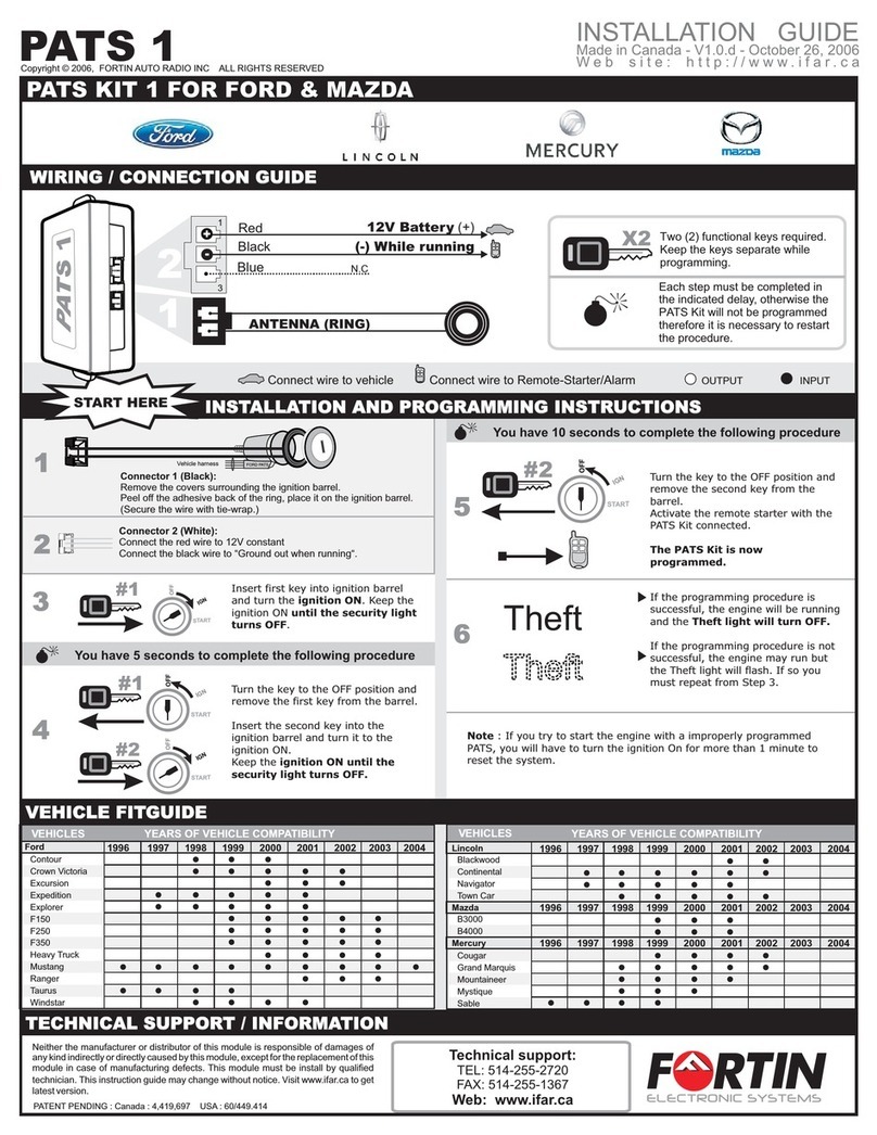
Fortin PATS 1 User manual

Fortin

Fortin PATS 1 User manual

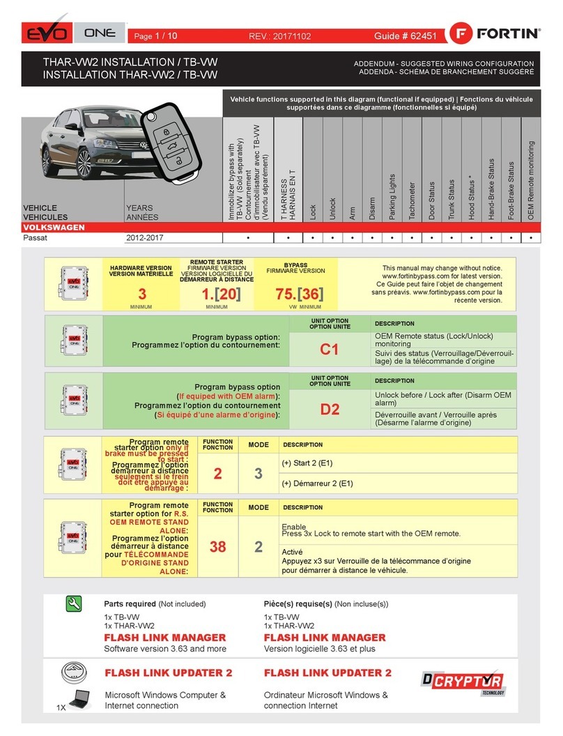
Fortin EVO ONE User manual

Fortin

Fortin EVO ONE User manual

Fortin EVO ONE User manual

Fortin

Fortin EVO ONE User manual

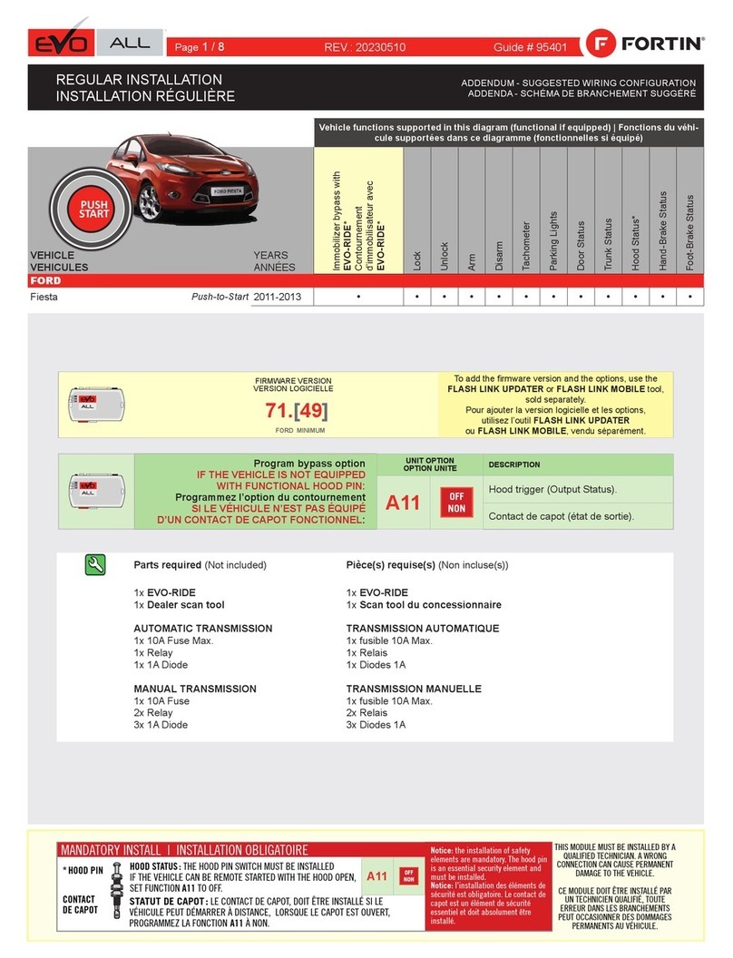
Fortin EVO-ALL User manual

Fortin

Fortin EVO-ALL User manual

Fortin EVO ALL Installation and operating instructions

Fortin

Fortin EVO ALL Installation and operating instructions

Fortin EVO ONE User manual

Fortin

Fortin EVO ONE User manual

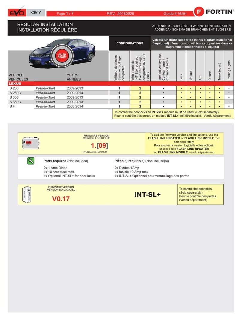
Fortin EVO-KEY User manual

Fortin

Fortin EVO-KEY User manual

Fortin EVO ONE User manual

Fortin

Fortin EVO ONE User manual

Fortin EVO-CHR T1 User manual

Fortin

Fortin EVO-CHR T1 User manual

Fortin EVO-CAN User manual

Fortin

Fortin EVO-CAN User manual

Fortin EVO-ALL User manual

Fortin

Fortin EVO-ALL User manual

Fortin EVO-ALL-CHRT6 User manual

Fortin

Fortin EVO-ALL-CHRT6 User manual

Fortin EVO-GMT1 User manual

Fortin

Fortin EVO-GMT1 User manual

Fortin EVO-ALL User manual

Fortin

Fortin EVO-ALL User manual

Fortin EVO ONE User manual

Fortin

Fortin EVO ONE User manual

Fortin Evo One THAR-VW6 User manual

Fortin

Fortin Evo One THAR-VW6 User manual

Fortin EVO ONE User manual

Fortin

Fortin EVO ONE User manual

Fortin EVO ALL User manual

Fortin

Fortin EVO ALL User manual

Fortin EVO ONE User manual

Fortin

Fortin EVO ONE User manual

Fortin EVO ONE THAR-GM7 User manual

Fortin

Fortin EVO ONE THAR-GM7 User manual

Fortin THAR-AUD1 User manual

Fortin

Fortin THAR-AUD1 User manual

Fortin INT-SL User manual

Fortin

Fortin INT-SL User manual

Fortin EVO ALL User manual

Fortin

Fortin EVO ALL User manual

Fortin EVO ONE User manual

Fortin

Fortin EVO ONE User manual

Popular Automobile Accessories manuals by other brands

Magneti Marelli AC161 Installation instruction

Magneti Marelli

Magneti Marelli AC161 Installation instruction

FDI uEZ GUI Start here

FDI

FDI uEZ GUI Start here

JCROffroad JT Install instructions

JCROffroad

JCROffroad JT Install instructions

Rostra VOXXElectronics 250-1930 owner's guide

Rostra

Rostra VOXXElectronics 250-1930 owner's guide

TOP VEHICLE TECH GR3FORD5 installation manual

TOP VEHICLE TECH

TOP VEHICLE TECH GR3FORD5 installation manual

Safe Fleet PRIME DESIGN AR-2000-BLK manual

Safe Fleet

Safe Fleet PRIME DESIGN AR-2000-BLK manual

Skoda Fabia Combi 5J Fitting instructions

Skoda

Skoda Fabia Combi 5J Fitting instructions

Camcar 40077 Al Mounting instructions

Camcar

Camcar 40077 Al Mounting instructions

Camcar 40089 AL Mounting instructions

Camcar

Camcar 40089 AL Mounting instructions

Impac Tradesman 2000 installation manual

Impac

Impac Tradesman 2000 installation manual

DVB OFFROAD BRSB-01 installation manual

DVB

DVB OFFROAD BRSB-01 installation manual

Safari Snorkel SS385HF installation guide

Safari Snorkel

Safari Snorkel SS385HF installation guide

ULTIMATE SPEED 279746 Assembly and Safety Advice

ULTIMATE SPEED

ULTIMATE SPEED 279746 Assembly and Safety Advice

SSV Works DF-F65 manual

SSV Works

SSV Works DF-F65 manual

ULTIMATE SPEED CARBON Assembly and Safety Advice

ULTIMATE SPEED

ULTIMATE SPEED CARBON Assembly and Safety Advice

Witter F174 Fitting instructions

Witter

Witter F174 Fitting instructions

WeatherTech No-Drill installation instructions

WeatherTech

WeatherTech No-Drill installation instructions

TAUBENREUTHER 1-336050 Installation instruction

TAUBENREUTHER

TAUBENREUTHER 1-336050 Installation instruction

manuals.online logo
manuals.online logoBrands
  • About & Mission
  • Contact us
  • Privacy Policy
  • Terms and Conditions

Copyright 2025 Manuals.Online. All Rights Reserved.