KNOVA KN RO-1313 User manual

KN RO-1313
Rebajadora de base fija
1300W
Fixed based
router

SAFETY SYMBOLS
Some of these following symbols may be used on this tool. Please
study them and learn their meaning. Proper interpretation of
these symbols will allow you to operate the tool better and
more safely.
Symbol Name Designation / Explanation
Volts
Amperes
Hertz
Watts
Alternating
current
No-load speed
Pounds
Class II
construction
Per minute
Eear safety
goggles
Voltage
Current
Frequency (cycles per second)
Power
Type of current
Type or characteristic
of current
Rotational speed at no load
Direct current
Weight
Double insulate construction
Revolutions, strokes, suface
speed orbits, etc., per minute
WARNING
The operation of any
power tool can result in foreign
objects being thrown into your
eyes, which can result in
severe eye damage. Before
beginning power tool operation,
always wear safety goggles or
safety glasses with side shields
and a full-face shield when
needed. We recommend a
Wide Vision Safety Mask for
use over eyeglasses or
standard safety glasses with
side shields. Always use eye
protection which is marked to
comply with ANSI Z87.1.
V
A
Hz
W
nº
.../min
WARNING
To ensure safety and reliability, all repairs
should be performed by a qualied service technician.
SAFETY INSTRUCTIONS
The purpose of safety symbols is to attract your attention to
possible dangers. The safety symbols, and the explanations with
them, deserve your careful attention and understanding. The
symbol warnings do not, by themselves, eliminate any danger.
The instructions and warnings they give are no substitutes for
proper accident prevention measures.
WARNING
Be sure to read and understand all safety
instructions in this manual, including all safety alert
symbols such as “DANGER,” “WARNING” and
“CAUTION” before using this tool. Failure to following
all instructions listed below may result in electric shock,
re, and/or serious personal injury.
SYMBOL MEANING
lbs
SAFETY ALERT SYMBOL: Indicates DANGER,
WARNING, OR CAUTION. May be used in conjunction
with other symbols or pictographs.
DANGER
Indicates an imminently hazardous situation,
which, if not avoided, will result in death or serious injury.
WARNING
Indicates a potentially hazardous situation,
which, if not avoided, could result in death or serious
injury.
CAUTION
Indicates a potentially hazardous situation,
which, if not avoided, could result in minor or moderate
injury.
NOTICE: (Without Safety Alert Symbol) Indicates a situation
that may result in property damage.
SAVE THESE INSTRUCTIONS!
GENERAL POWER TOOL SAFETY WARNINGS
WARNING
Read all safety warnings and all instructions.
Failure to follow the warnings and instructions may
result in electric shock, re and/or serious injury.
Save all warnings and instructions for future reference.
The term “power tool” in the warnings refers to your
mains-operated (corded) power tool or battery-operated
(cordless) power tool.
1. Keep work area clean and well lit. Cluttered and dark
areas invite accidents.
2. Do not operate power tools in explosive atmospheres,
such as in the presence of ammable liquids, gases or
dust. Power tools create sparks which may ignite the
dust or fumes.
3. Keep children and bystanders away while operating a
power tool. Distractions can cause you to lose control
WORK AREA SAFETY
1. Power tool plugs must match the outlet. Never modify the
plug in any way. Do not use any adapter plugs with earthed
(grounded) power tools. Unmodied plugs and matching
outlets will reduce risk of electric shock.
2. Avoid body contact with earthed or grounded surfaces,
such as pipes, radiators, ranges and refrigerators. There
is an increased risk of electric shock if your body is
earthed or grounded.
3. Do not expose power tools to rain or wet conditions. Water
entering a power tool will increase the risk of electric shock.
4. Do not abuse the cord. Never use the cord for carrying,
pulling or unplugging the power tool. Keep cord away from
heat, oil, sharp edges or moving parts. Damaged or
entangled cords increase the risk of electric shock.
5. When operating a power tool outdoors, use an extension
cord suitable for outdoor use. Use of a cord suitable for
outdoor use reduces the risk of electric shock.
6. If operating a power tool in a damp location is unavoidable,
use a ground-fault circuit interrupter (GFCI) protected
supply. Use of a GFCI reduces the risk of electric shock.
ELECTRICAL SAFETY

SAFETY INSTRUCTIONS
1. Stay alert, watch what you are doing and use common
sense when operating a power tool. Do not use a power
tool while you are tired or under the inuence of drugs,
alcohol or medication. A moment of inattention while
operating power tools may result in serious personal injury.
2. Use personal protective equipment. Always wear eye
protection. Protective equipment such as dust mask,
non-skid safety shoes, hard hat, or hearing protection used
for appropriate conditions will reduce personal injuries.
3. Prevent unintentional starting. Ensure the switch is in the
off-position before connecting to power source and/or
battery pack, picking up or carrying the tool. Carrying
power tools with your nger on the switch or energising
power tools that have the switch on invites accidents.
4. Remove any adjusting key or wrench before turning the
power tool on. A wrench or a key left attached to a rotating
part of the power tool may result in personal injury.
5. Do not overreach. Keep proper footing and balance at all
times. This enables better control of the power tool in
unexpected situations.
6. Dress properly. Do not wear loose clothing or jewellery.
Keep your hair, clothing and gloves away from moving
parts. Loose clothes, jewellery or long hair can be caught in
moving parts.
7. If devices are provided for the connection of dust
extraction and collection facilities, ensure that these are
connected and properly used. Use of these devices can
reduce dust-related hazards.
PERSONAL SAFETY
1. Have your power tool serviced by a qualied repair person
using only identical replacement parts. This will ensure that
the safety of the power tool is maintained.
SERVICE
1. Hold the power tool by insulated gripping surfaces only,
because the cutter may contact its own cord. Cutting a
“live” wire may make exposed metal parts of the power
tool “live” and could give the operator an electric shock.
2. Use clamps or another practical way to secure and
support the workpiece to a stable platform. Holding
the work by your hand or against the body leaves it
unstable and may lead to loss of control.
SAFETY GUIDELINES FOR ROUTERS
1. Always make sure the work surface is free from nails and
other foreign objects. Cutting into a nail can cause the bit
and the tool to jump and damage the bit.
2. Never hold the workpiece in one hand and the tool in the
other hand when in use. Never place hands near or below
cutting surface. Clamping the material and guiding the tool
with both hands is safer.
3. Never lay workpiece on top of hard surfaces, like concrete,
stone, etc.. Protruding cutting bit may cause tool to jump.
4. Always wear safety goggles and dust mask. Use only in
well ventilated area. Using personal safety devices and
working in safe environment reduces risk of injury.
5. Keep handles dry, clean and free from oil and grease.
Slippery hands cannot safely control the power tool.
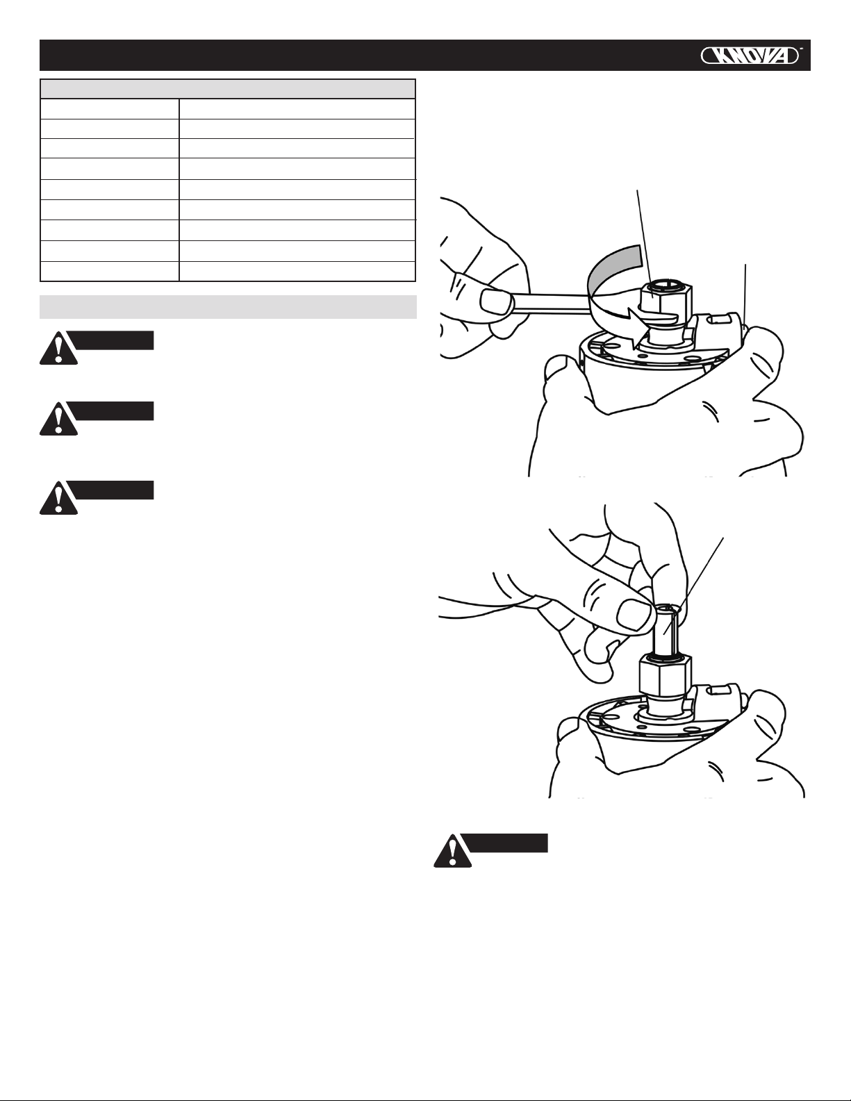
6. After changing the bits or making any adjustments, make
sure the collet nut and any other adjustment devices are
securely tightened. Loose adjustment device can
unexpectedly shift, causing loss of control, loose rotating
components will be violently thrown.
ADDITIONAL SAFETY GUIDELINES FOR ROUTERS
7. Never start the tool when the bit is engaged in
the material. The bit cutting edge may grab the material
causing loss of control of the cutter.
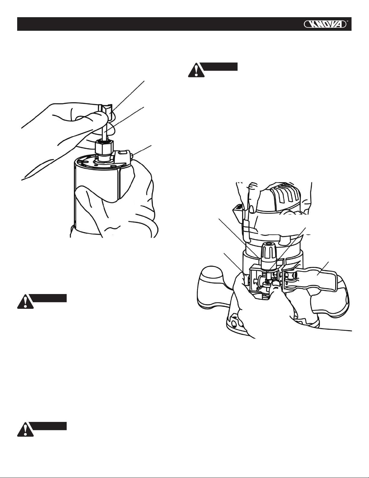
8. Always hold the tool with two hands during start-up. The
reaction torque of the motor can cause the tool to twist.
9. The direction of feeding the bit into the material is very
important and it relates to the direction of bit rotation.
When viewing the tool from the top, the bit rotates
clockwise. Feed direction of cutting must be
counter-clockwise. NOTE: inside and outside cuts will
require different feed direction, refer to section on feeding
the router. Feeding the tool in the wrong direction, causes
the cutting edge of the bit to climb out of the work and pull
the tool in the direction of this feed.
10. Never use dull or damaged bits. Sharp bits must be
handled with care. Damaged bits can snap during use.
Dull bits require more force to push the tool, possibly
causing the bit to break.
11. Never touch the bit during or immediately after the use.
After use the bit is too hot to be touched by bare hands.
12. Never lay the tool down until the motor has come to a
complete standstill. The spinning bit can grab the surface
and pull the tool out of your control.
13. Never use bits that have a cutting diameter greater than
the opening in the base.
WARNING
Some dust created by power sanding,
sawing, grinding, drilling and other construction
activities contains chemicals known to the state of
California to cause cancer, birth defects or other
reproductive harm. Some examples of these
chemicals are:
• Lead from lead-based paints
• Crystalline silica from bricks and cement and other
masonry products, and
• Arsenic and chromium from chemicallytreated lumber.
Your risk from these exposures varies, depending on how often
you do this type of work. To reduce your exposure to these
chemical: work in a well ventilated area, and work with
approved safety equipment, such as those dust masks that are
specially designed to lter out microscopic particles.

OVERVIEW
Variable-speed dial
ON/OFF switch
Handle
Collet
Base plate
Spindle-lock button
LED worklight
Handle
Live tool indicator
Fine-adjustment dial
Handle
Motor
clamp
Lock
nut
Dust-extraction
adaptor
Handle
Coarse-adjustment
button
Dust-extraction
adaptor
Collet
wrench
1/4”
Collet
Screws

SPECIFICATIONS
Model
Rated voltage:
Rated power input:
Max HP:
Speed:
Collet capacity:
Base dimension:
Inside base diameter:
Micro-fine depth:
Weight:
KN RO-1313
120 V ~ 60 Hz
11 A
2.0 HP
11,000 - 25,000 r/min
1/4” & 1/2” (6.35 mm & 12.7 mm)
Fixed base 6” (152.4 mm)
2” (50.8 mm)
Fixed base adjusts to 1/64” (0.4 mm)
8 lbs. (3.6 kg)
ASSEMBLY
WARNING
WARNING
WARNING
If any part is broken or missing, DO NOT
attempt to plug in the power cord or operate the tool
until the broken or missing part is replaced. Failure to
do so could result in possibly serious injury.
Do not attempt to modify this tool or
create accessories not recommended for use with this
tool. Any such alteration or modication is misuse
and could result in a hazardous condition leading to
possible serious injury.
Your tool should never be connected to
the power source when you are assembling parts,
making adjustments, installing or removing blades,
cleaning, or when it is not in use. Disconnecting the
tool will prevent accidental starting, which could cause
serious personal injury.
Router, xed base, collets, collet wrench, dust-extraction
adaptor and instruction manual.
CONTENTS
1. Carefully remove the tool and any accessories from the
carton. Make sure that all items listed in the packing list
are included.
2. Inspect the tool carefully to make sure that no breakage
or damage occurred during shipping.
3. Do not discard the packing material until you have carefully
inspected and satisfactorily operated the tool.
UNPACKING
This router comes with 1/2”collet and 1/4” collet sleeve that
accept cutter bits with 1/2” and 1/4” shanks, respectively.
The 1/2” collet is installed on the tool; the 1/4” collet sleeve
can be installed inside of the 1/2” collet.
1. Disconnect the plug from the power supply.
2. Remove the router motor from the base; refer to the section
“REMOVING MOTOR FROM BASE”.
3. Set the router motor upside down on its top cap, with
the collet pointing up.
4. Press the spindle-lock button to engage and lock the spindle
shaft and collet nut (FIG. 1).
5. Place the collet wrench on the collet nut and turn it
counterclockwise to loosen the collet nut slightly to accept
the cutter bit shank.
SELECTING THE COLLET
INSTALLING THE 1/4” COLLET SLEEVE (FIG. 1-2)
6. Insert the 1/4” collet sleeve into the 1/2” collet assembly
as far as it will go (FIG. 2).
7. With the 1/4” collet sleeve inserted and the spindle-lock
button pressed in to engage the shaft, place the collet
wrench on the collet nut and turn it clockwise until the 1/4”
collet sleeve is tightened on the 1/2” collet nut.
Collet nut
Spindle-lock
button
Fig. 1
Fig. 2
1/4” Collet
REPLACING THE CUTTER BIT
CAUTION:
Always ensure that the tool is switched
OFF and unplugged from the power supply before
installing or removing bits or accessories.
INSTALLING THE CUTTER BIT (FIG. 3)
1. Disconnect the plug from the power supply.
2. Remove the router motor from the base; refer to the section
“REMOVING MOTOR FROM BASE”.
3. Set the router motor upside down on its top cap, with
the collet pointing up.
4. Press the spindle-lock button to engage and lock the spindle
shaft and collet nut.

ASSEMBLY
5. Place the collet wrench on the collet nut and turn it
counterclockwise to loosen the collet nut slightly in order
to accept the cutter bit shank.
6. Insert the cutter bit shank into the collet assembly as far as
it will go, then back the shank out until the cutters are
approximately 1/8” to 1/4” away from the face of
the collet (FIG. 3).
Fig. 3
Cutters
Bit shank
Spindle-lock
button
7. With the cutter bit inserted and the spindle-lock button
pressed in to engage the shaft, place the collet wrench on
the collet nut and turn it clockwise until the cutter bit is
rmly tightened on the collet nut.
NOTICE: To ensure proper gripping of the cutter bi
shank and minimize run-out, the shank of the cutter
bit must be inserted into the collet nut at least 5/8”.
WARNING
Tighten the collet nut securely to prevent
the cutter bit from slipping. If the collet nut is not
securely tightened, the cutter bit may detach during
use, causing serious personal injury.
1. Disconnect the plug from the power supply.
2. Remove the router motor from the base; refer to the section
“REMOVING MOTOR FROM BASE”.
3. Set the motor upside down on its top cap, with the collet
pointing up.
4. Press the spindle-lock button to engage and lock the spindle
shaft and collet nut.
5. Place the wrench on the collet nut and turn it
counterclockwise to loosen the collet nut slightly.
6. Remove the cutter bit shank.
REMOVING THE CUTTER BIT
INSTALLING MOTOR IN FIXED BASE (FIG. 4)
WARNING
Never use the router motor without
installing it into an approved base. Failure to do so
could result in serious personal injury and damage to
motor.
NOTICE: Before installing the motor housing in the xed
base, have the collet nut and router cutter bit installed on
the motor housing; refer to the section “REPLACING
THE CUTTER BIT”.
CAUTION:
Always ensure that the tool is switched
OFF and unplugged from the power supply before
installing or removing bits or accessories.
1. Disconnect the plug from the power supply.
2. Place the xed base on a at surface.
3. With the back of xed base facing you, open the motor
clamp.
4. Press in the coarse-adjustment button while you align
the coarse-adjustment notches on the motor with the slot
in the xed base.
5. Slide the motor down into the xed base.
6. The router motor will now slide up or down to set
adjustments when the coarse-adjustment button is
pressed in.
7. After all adjustments are made, close the router clamp
securely.
1. Disconnect the plug from the power supply.
2. Place the router on a at surface.
3. With the back of the router facing you, open the router
motor clamp.
4. Push in the coarse-adjustment button while you lift router
motor out of the xed base.
5. Set the motor upside down on its top cap with the collet
pointing up and remove cutter bit.
REMOVING MOTOR FROM THE FIXED BASE (FIG. 4)
Coarse-adjustment
notches
Motor clamp
Slot
Coarsea-djustment
button
Fig. 4
To attach the dust-extraction adaptor onto the xed base,
position and secure it to the base with the screws (included)
as shown in FIG. 5.
INSTALLING THE DUST-EXTRACTION ADAPTOR (FIG. 5)

ASSEMBLY
Dust-extraction
adaptor
Fixed base
Fig. 5
ADJUSTING THE DEPTH OF CUT
WARNING
Your router should never be turned on or
be connected to the power source when you are
assembling parts, making adjustments, installing or
removing collets/nuts and cutter bits, cleaning or
when it is not in use. Disconnecting the router will
prevent accidental starting, which could cause serious
personal injury.
DEPTH ADJUSTMENT WITH FIXED BASE (FIG. 6)
NOTICE: All depth adjustments on the xed base must be
made with the motor clamp open.
NOTICE: For all xed base routers, the cutter bit depth equals
the amount of the cutter that is exposed below the surface
of the sub-base.
The xed base is designed with a neadjustment system. When
the bit is lowered to the approximate position desired (coarse
setting), the system can then be microadjusted to the precise
depth.
Fine-adjustment
dial
Depth-indicator
ring
Fig. 6
COARSE ADJUSTMENT:
Depressing the coarse-adjustment button allows you to quickly
lower or raise the cutter bit to an approximate depth setting.
FINE ADJUSTMENTS:
NOTICE: Be sure that the worm gear system is engaged
before making ne adjustments. Test it by rotating the
neadjustment dial to check that the bit lowers and raises.
If it does not, press in the coarse-adjustment button and turn
the ne-adjustment dial until the gears engage, then reset
zero “0” on the depthindicator ring.
The depth-indicator ring located on the ne-adjustment dial is
marked in 1/64” increments. Turning the ne-adjustment dial
clockwise 180º (1/2 turn), lowers the cutter bit 1/16”. One full
turn clockwise 360° (zero “0” to zero “0”) lowers the bit 1/8”.
The system allows a maximum of 17 full 360º revolutions
clockwise, to lower the cutter bit a total of 2 1/8 inch (54mm).
The depth-indicator ring may be reset to zero “0” without
moving the ne-adjustment dial. This allows the user to begin
adjustments from any reference point desired.
ADJUSTING DEPTH (FIG. 7)
1. Disconnect the plug from the power supply.
2. Place the router on a at surface with the back of the xed
base facing you. Open the motor clamp.
3. With the cutter bit already installed, press in
the coarse-adjustment button and lower the motor into
the base until the cutter bit is close to the at surface on
which the base is sitting. Turn the ne-adjustment dial
until the cutter bit “just” touches the at surface on which
the base is sitting. Then lock the motor clamp.
4. Place the router on two level pieces of wood, positioned
so that the cutter bit can be lowered below the sub-base
(FIG. 7).
5. Turn the ne-adjustment dial clockwise to lower the bit
to the desired depth of cut. Turn the dial counterclockwise
to raise the cutter bit.
6. Once the depth of cut is set, close the motor clamp securely.
Fig. 7
DEEP CUTS
The proper cutting depth for each pass, is always determined
by the material, the cutter bit size and type, and the power of
the motor.

OPERATION
Always make several progressively deeper cuts by starting
at one depth and then making several passes, each time
increasing the cutting depth until your desired depth is reached.
Making a cut that is too deep will stress the motor and
the cutter bit, and it may burn the workpiece and dull the cutter
bit. It could also “grab” too much of the workpiece and cause
you to lose control of the router, causing a serious accident.
To be certain that your depth settings are correct, always make
test cuts in scrap material similar to your workpiece before
beginning your nal cutting.
Remember, knowing the right depth for each cut comes with
routing experience.
TOGGLE “ON/OFF” SWITCH (FIG. 8)
Your router motor is turned “ON” and “OFF” with the toggle
switch located on the top cap of the motor housing.
The left side of the toggle switch hood (as you face it) is marked
“I” and “ON” and the right side (as you face it) is marked “O”
and “OFF.”
• To turn the motor “ON”, push the toggle switch to the left
side marked “I” and “ON.”
• To turn the motor “OFF” push the toggle switch to
the right side marked “O” and “OFF.”
When using the xed base for edge routing, always hold
the router and the cutter bit away from the workpiece when
turning the toggle switch “On.” Only contact the workpiece
with the router and cutter bit after the router has reached
the full selected speed; read and follow the instructions for
EDGE ROUTING and INTERNAL ROUTING with the base you
are using. Only remove the router and cutter bit from
the workpiece after turning the router motor “OFF” and after
the cutter bit comes to a complete stop.
Fig. 8
SOFT START FEATURE
The soft start control minimizes torque twist, customary in
larger router motors, by limiting the speed at which the motor
starts. This increases the motor’s life.
LED WORKLIGHTS (FIG. 9)
Your router motor has 3 built-in worklights located around
the collet/nut to provide high visibility of the workpiece when
cutting. These lights are always “On” when the toggle switch
is in the “ON” position.
Fig. 9
“LIVE TOOL INDICATOR” LIGHT (FIG. 10)
Your router also has a “live tool indicator” green light, located
on the motor housing top cap where the power cord enters
the motor housing. This green light is always on when the router
motor is plugged into a power source.
Fig. 10
Live tool
indicator
ELECTRONIC VARIABLE SPEED CONTROL (FIG. 11)
The electronic speed control feature allows the motor speed to
be matched to the cutter size and material for an improved
nish and extended bit life.
Speed changes are made starting at “1” and rotating
the speed control dial clockwise increase the speed, and
counter-clockwise to decrease the speed as indicated on
the Dial, numbered 1 through 6.

OPERATION
Fig. 11
Variable-speed dial
NOTICE: The speed may be changed while the router is “ON”,
but do not change the speed if the cutter bit is in the workpiece.
NOTICE: Choose the applicable cutting speed according
the bit diameter and the material being cut.
WARNING
Before operating your router, follow all
safety instructions in this manual. Failure to do so
could result in serious personal injury.
EDGE ROUTING OR INTERNAL ROUTING (FIG. 12)
For ease of operation and to maintain proper control, your
router has two handles, one on each side of the router base.
When operating the router, always hold it rmly with both hands
(FIG. 12).
Fig. 12
EDGE ROUTING (FIG. 13)
1. With the depth-of-cut set, place the router on the edge
of workpiece, making sure that the cutter does not contact
the workpiece.
2. Turn the router “ON,” and allow the router motor to reach
the selected speed.
3. To begin the cut, gradually feed the cutter bit into
the edge of the workpiece.
4. When the cut is complete, turn the router motor “OFF”
and allow the cutter bit come to a complete stop before
removing it from the workpiece.
5. Unplug the
router from
the power
source, and
inspect the
nished cut.
Fig. 13
WARNING
Always securely clamp your workpiece
and keep a rm grip on the router base with both
hands at all times. Failure to do so could result in
loss of control causing possible serious personal
injury.
WARNING
Removing the cutter bit from
the workpiece while it is still rotating could damage
the workpiece and result in loss of control, causing
serious personal injury.
INTERNAL ROUTING WITH FIXED BASE (FIG. 14)
1. With the depth-of-cut set, tilt the router and place it on
the workpiece with the leading edge of the sub-base
contacting the workpiece rst (FIG. 14).
2. Turn the router motor “ON” and allow the router motor
to reach the selected speed, being careful not to allow
the cutter bit to contact the workpiece.
3. To begin your cut, gradually lower the cutter bit into
the workpiece until the subbase is ush with the workpiece
(FIG. 14).
4. When the cut is complete, turn the router motor “OFF”
and allow the cutter bit come to a complete stop before
removing it from the workpiece.
5. Unplug the router from power source, place the router
upside down on the worktable, and inspect the nished
cut in the workpiece.

OPERATION
Fig. 14
WARNING
Always securely clamp your workpiece
and keep a rm grip on the router base with both
hands at all times. Failure to do so could result in
loss of control causing possible serious personal
injury. If using a router table, large cutter bits should
be used for edging only.
FREEHAND ROUTING WITH THE FIXED BASE (FIG. 15)
WARNING
Do not use large cutter bits for freehand
routing. Using large cutter bits when freehand routing
could cause loss of control or create other hazardous
conditions that could result in personal injury. If using
a router table, large bits should be used for edging
only.
When used freehand, the router becomes a exible and
versatile tool. This exibility makes it possible to easily
rout signs, relief sculptures, etc.
When freehand routing:
1. Draw or lay out the pattern on the workpiece.
2. Choose the appropriate bit.
3. Follow the instructions for INTERNAL ROUTING, and rout
the pattern in two or more passes. Do not exceed 1/8”
depth of cut in a single pass. This will help provide better
control, as well as serve as a guide on the next passes.
NOTICE: A core-box bit or V-groove bit is often used for
routing letters and engraving objects. Straight bits and ball
mills are often used to make relief carvings. Veining bits are
used to carve small, intricate details.
NOTICE: Making a single deep cut is never advisable.
Smaller-diameter bits are easily broken by too much side thrust
and torque. Larger bits will cause a rough cut and be difcult to
guide and control. For these reasons, do not exceed 1/8” depth
of cut in a single pass.
WARNING
Always securely clamp your workpiece
in place, and keep a rm grip on the router base with
both hands at all times. Failure to do so could result
in loss of control causing possible serious personal
injury.
EDGING WITH A PILOT BIT (FIG. 16-17)
Arbor-type bits with pilots are excellent for edge shaping of any
workpiece edge that is either straight or curved at a curvature
as great as or greater than the radius of the bit to be used.
The pilot prevents the bit from making an excessively deep cut;
and holding the pilot rmly in contact with the workpiece edge
throughout prevents the cut from becoming too shallow.
Fig. 15
Fig. 16
Motor housing
Fixed base
sub-base
Spindle lock
Cutter bit
Pilot Work piece
Work piece
Guide board
TOP EDGE SHAPING
Whole edge
of workpiece
WHOLE EDGE SHAPING
Fig. 17

OPERATION
TOP EDGE SHAPING (FIG. 16)
Whenever the workpiece thickness, together with the desired
depth of cut (as adjusted by the cutting-depth setting) are such
that only the top part of the edge is to be shaped (leaving at least
a 1/16”. thick uncut portion at the bottom), the pilot can ride
against the uncut portion, which serves to guide it (FIG. 16).
WHOLE EDGE SHAPING (FIG. 17)
If the workpiece is too thin or the bit is set so low that there will
be no uncut edge against which to ride the pilot, an extra board
must be placed under the workpiece to act as a guide (FIG. 17).
This “guide” board must have exactly the same contour - straight
or curved - as the workpiece edge. If it is positioned so that its
edge is ush with the workpiece edge, the bit will make a full cut
(in as far as the bit radius). On the other hand, if the guide is
positioned so that it extends beyond the edge of the workpiece),
the bit will make less than a full cut - which will alter the shape
of the nished edge.
NOTICE: The size (diameter) of the pilot that is used determines
the maximum cut width that can be made with the pilot against
the workpiece edge. (The small pilot exposes the entire bit; the
large one reduces this amount by 1/16”.) Any of the piloted
cutter bits can be used without a pilot for edge shaping with
guides.
WARNING
Always securely clamp your workpiece
and keep a rm grip on the router base with both
hands at all times. Failure to do so could result in loss
of control causing possible serious personal injury.
FEEDING THE ROUTER (FIG. 18)
The secrets to professional routing are a careful set-up for
the cut, selecting the proper depth of cut, knowing how
the cutter bit reacts in your workpiece, and the rate and
direction of feed of the router.
Router feed direction
Router feed
direction
Fig. 18
DIRECTION OF FEED - EXTERNAL CUTS (FIG. 18)
The cutter bit rotates clockwise. Feeding the bit from left to
right will cause the bit to pull the router towards the workpiece
(FIG. 18). If the router is fed in the opposite direction (right to
left), the rotating force of the cutter bit will tend to throw
the bit away from the workpiece.
This is called “Climb-Cutting”. “Climb-Cutting” may cause loss
of control, possibly resulting in personal injury. When
“Climb-Cutting” is required (e.g. backing around a corner),
exercise extreme caution to maintain control of the router.
The high speed of the cutter bit during a proper feeding
operation (left to right), results in very little kickback under
normal conditions. However, if the cutter bit strikes a knot,
an area of hard grain, or a foreign object, “Kickback” may
result. Kickback may damage your workpiece and could cause
you to lose control of the router, possibly causing personal
injury. Kickback is always in the opposite direction of
the clockwise cutter bit rotation, or counterclockwise.
To guard against and help prevent Kickback, plan your set-up
and direction of feed so that you’re always keeping the sharp
edges of the cutter bit biting straight into uncut wood. Always
inspect your workpiece for knots, hard grain, and foreign
objects.
KICKBACK
Because of the high speed of the cutting bit during a proper
feeding operation (left to right), there is very little kickback
under normal conditions. However, if the cutting bit strikes a
knot, an area of hard grain in the workpiece, or a foreign object,
the normal cutting action could be affected and cause “Kickback.”
This Kickback may cause damage to your workpiece, and could
cause you to lose control of the router, possibly causing serious
personal injury. Kickback is always counterclockwise:
the opposite direction of the clockwise cutting bit rotation.
To guard against and help prevent Kickback, Always inspect
the workpiece for knots, hard grain, and foreign objects that
could cause a kickback problem and plan the setup and direction
of feed so that the router is always moving, and keep the sharp
edges of the cutting bit continuously biting straight into new
(uncut) wood (workpiece).
WARNING
Kickback causes the power tool to jerk
back toward the user, causing possible loss of control
and serious injury. Always take precautions against
kickback as described in the operator’s manual.
DIRECTION OF FEED – INTERNAL CUTS (FIG. 19-20)
When making an internal cut, such as a groove, dado, or slot,
always try to have the guide you are using with the router (edge
guide, straight edge, board guide), on the right-hand side of
the router as you make the cut (FIG. 19).
When the guide is positioned on the right hand side of the
router, the router travel should be from left to right and
“counterclockwise” around curves (FIG. 19). This
counterclockwise action around the curve could cause “Climb
cutting”. Always be alert and exercise extreme caution to
maintain control of the router when making this type of cut
around curves.
When the guide is positioned as shown in FIG. 20, the router
travel should be from left to right and clockwise around curves.
If there is a choice, the set-up in FIG. 20 is easier to use, but
there is the possibility of “Climb Cutting” around curves. In
either case, FIG. 19 or FIG. 20, the sideways thrust of the router
cutting is always against the guide, as is proper.

OPERATION
ROUTER FEED DIRECTION
Fig. 19
Fig. 20
GUIDE
THRUST
BIT
ROTATION
BIT
ROTATION
GUIDE OUTSIDE
GUIDE INSIDE
BIT
ROTATION
BIT
ROTATION
THRUST
ROUTER FEED DIRECTION
GUIDE
WARNING
Always securely clamp the workpiece in
place, and keep a rm grip on the router base with
both hands at all times. Failure to do so could result in
loss of control causing possible serious personal injury.
RATE OF FEED (FIG. 21-22)
The proper rate of feed depends on several factors:
the hardness and moisture content of the workpiece, the depth
of cut, and the cutting diameter of the bit.
When cutting shallow grooves in soft woods, such as pine, you
may use a faster rate of feed. When making deep cuts in
hardwoods, such as oak, you should use a slower rate of feed.
Bit shank
TOO FAST
Cutter
Cut
Fig. 21
FEEDING TOO RAPIDLY (FIG. 21)
Clean and smooth nished cuts can only be achieved when
the cutting bit is rotating at a relatively high speed, taking very
small bites, and producing tiny, clean-cut chips.
Forcing the feed of the cutting bit forward too rapidly slows
the revolution of the cutting bit, and the bit takes larger bites
as it rotates. Larger bites mean larger chips and a rough nish.
This forcing action can also cause the router motor to overheat.
Under extreme force-feeding conditions, the revolutions can
become so slow and the bites become so large that chips are
only partially cut off, causing splintering and gouging of
the workpiece.
The router will make clean, smooth cuts if it is allowed to run
freely without the overload of forced feeding. You can detect
forced feeding by the sound of the motor. Its usual high-pitched
whine will sound lower and louder as it loses speed. Holding
the router against the workpiece will also be more difcult to do.
FEEDING TOO SLOWLY (FIG. 22)
When you feed the cutting bit too slowly, the rotating cutting
bit does not cut into new wood rapidly enough to take a bite.
Instead, it scrapes away sawdust-like particles. This scraping
produces heat, which can glaze, burn, and mar the cut in
the workpiece and, in extreme cases, overheat the cutting bit.
When the cutting bit is scraping instead of cutting, the router is
more difcult to control as you feed it.
With almost no load on the motor, the cutting bit has a tendency
to bounce off the sides of the cut in the workpiece, producing
a cut with a rippled nish instead of clean, straight sides.
Cutter
Bit shank
Cut
TOO SLOW
Fig. 22

MAINTENANCE
Before cleaning or performing any maintenance, verify that
the router has been disconnected from the power supply. Keep
all ventilation openings clean. Avoid using solvents when
cleaning plastic parts. Most plastics are susceptible to damage
from various types of commercial solvents. Use a clean cloth to
remove dirt, oil, and grease.
If the supply cord is damaged, it must be replaced by a specially
prepared cord available through the service organization.
WARNING
WARNING
Do not let brake uids, gasoline,
petroleum-based products, penetrating oil, etc. come
into contact with plastic parts. They contain chemicals
that can damage, weaken, or destroy plastic.
To ensure safety and reliability, all repairs
should be performed by a qualied service technician.
REPLACEMENT OF CARBON BRUSHES (FIG. 23)
1. Disconnect the plug from the power supply.
2. Replace both carbon brushes when either has less than
1/4-in. length of carbon remaining, or if the spring or wire
is damaged or burned.
3. Using a slotted screwdriver, remove the black, plastic cap
on each side of the router motor (FIG. 23) and carefully
withdraw the spring-loaded brush assemblies. Keep brushes
clean and sliding freely in their guide channels.
NOTICE: To reinstall the same brushes, make sure that the
brushes go back in the same way they came out. This will avoid
the need for a break-in period.
4. Insert new brush assemblies into the guide channels with
the carbon part going in rst, being certain to t the two
metal “ears” into their slots in the channel (FIG. 23).
5. Remember to replace both end caps after inspecting or
servicing brushes. Tighten the caps snugly, but do not
overtighten. The router should be allowed to “run in” (run
at no load without a cutter bit) for 5 minutes before use,
to seat the new brushes properly.
WARNING
For your safety, always turn off the switch
and unplug the router motor from the power source
before performing any maintenance or cleaning.
TROUBLESHOOTING
PROBLEM CAUSE SOLUTION
The router does
not work
Plug is not plugged into the
power source.
Switch is in “OFF” position.
The carbon brushes have
worn out completely.
The bit is dull.
Routing at an inappropriate
bit speed.
Bit size is inappropriate
for the collet/nut.
Plug the detachable cord into the power source.
Pull the switch to “ON” position.
Remove the brush caps, and replace the old brushes
with new ones.
Change to a sharp bit.
Select an appropriate bit speed.
Use only 1/4” diameter bits with the 1/4” collet; use
only 1/2” diameter bits with the 1/2” collet.
The surface of
the workpiece
is not smooth
after cutting
Bit cannot be
installed
Fig. 23
Cap
Brushes
Ears

21 Tapping screw 2
22 Fan bafe 1
Rotor 1
Ball bearing 1
Motor housing 1
203 LED holder ASSY 1
Ball bearing 1
Thread forming screw 3
Nut 1
23 Spindle lock 1
24 E Ring 1
25 Stop spring 1
26 Screw 2
27 Gear rack 1
28 Collet assembly 1
29 Chip shield 1
30 Hexagon socket screw 2
31 Handle 1
32 Lock bolt 2
33 Handle 1
Mounting 1
Located pin 1
Base plate 1
Hexagon nut 2
1 Thread forming screw 2
2 Transparent cap 1
3 Rear cover 1
4 Tapping screw 2
5 Power supply indicator 1
6 Speed adjustor assy 1
7 Hexagon socket screw 2
8 Thread forming screw 2
9 Brush holder cover 2
10 Carbon brush 2
11 Seal ring 1
12 Switch 1
13 Tapping screw 2
14 Cord anchorage 1
Middle housing 1
Brush holder 2
Power cord & plug 1
Cord guard 1
Receptacle 2
Sleeve 2
17 Bearing holder 1
18 Rubber spring 1
19 Washer 1
20 Stator 1
ELECTRIC DIAGRAM
No. Part name
Qty
201
202
No. Part name
Qty
204
34
No. Part name
Qty
35 Screw 3
36 Screw 1
37 Adjusting knob 1
38 Indicator 1
39 Screw 1
40 Worm 1
41 Wave washer 1
42 Shaft 1
205 Shaft assembly 1
43 Gear 1
44 Lock gear 1
45 Spring 1
46
Prevailing torque hexagon nut
1
47 Plate 1
48 E Ring 1
49 Lock pin 1
50 Clamping lever 1
51 Screw 1
52 Screw 2
53 Screw with nut 2
54 Parallel guide 1
55 Guiding rod 2
56 Vacuum adapter 1
57 Wrench 1
58 Collet assembly 1
PART LIST
Switch Stator
Stator
ROTOR
PCB
AC 120V, 60Hz

EXPLOSIVE DIAGRAM
Rebajadora de base fija
1300W
Fixed based
router
KN RO-1313

SÍMBOLOS DE SEGURIDAD
Algunos de los siguientes símbolos pueden utilizarse en esta
herramienta. Estúdialos y aprende su signicado.
La interpretación adecuada de estos símbolos le permitirá
operar la herramienta mejor y con mayor seguridad.
Símbolo Nombre Designación / Explicación
Voltios
Amperios
Hertz
Vatios
Alterno actual
Si velocidad
de carga
Libras
Clase II
construcción
Por minuto
Seguridad
auditiva
gafas de
protección
Voltaje
Actual
Frecuencia (ciclo por segundo)
Potencia
Tipo de corriente
Tipo o caracteriística
de corriente
Velocidad de rotación sin carga
Corriente
continua
Peso
Construcción de
doble aislamiento
Revolución, golpes, superficie
órbitas de velocidad, etc., por minuto
ADVERTENCIA
El funcionamiento
de cualquier La herramienta
eléctrica puede provocar que
se le arrojen objetos extraños
a los ojos, lo que puede provocar
daño ocular severo. Antes de
comenzar a utilizar la herramienta
eléctrica, siempre use gafas de
seguridad o anteojos de
seguridad con protectores
laterales y un protector facial
completo cuando sea necesario.
Recomendamos una máscara de
seguridad de visión amplia para
usar sobre anteojos o Gafas de
seguridad estándar con
protectores laterales. Utilice
siempre protección para los
ojos que esté marcada para
cumplir con ANSI Z87.1.
V
A
Hz
W
nº
.../min
Para garantizar la seguridad y
conabilidad, todas las reparaciones deben ser
realizadas por un técnico de servicio calicado.
LAS INSTRUCCIONES DE SEGURIDAD
El propósito de los símbolos de seguridad es llamar su atención
sobre posibles peligros. Los símbolos de seguridad y las
explicaciones que los acompañan merecen su cuidadosa
atención y comprensión. Los símbolos de advertencia no
eliminan por sí mismos ningún peligro. Las instrucciones y
advertencias que dan no sustituyen a las medidas adecuadas
de prevención de accidentes.
Asegúrese de leer y comprender
todas las instrucciones de seguridad de este manual,
incluidos todos los símbolos de alerta de seguridad
como “PELIGRO”, “ADVERTENCIA” y “PRECAUCIÓN”
antes de utilizar esta herramienta. El incumplimiento de
todas las instrucciones que se enumeran a continuación
puede provocar una descarga eléctrica, un incendio
y / o lesiones personales graves.
SÍMBOLO SIGNIFICADO
lbs
SÍMBOLO DE ALERTA DE SEGURIDAD: Indica
PELIGRO, ADVERTENCIA O PRECAUCIÓN. Puede
usarse junto con otros símbolos o pictografías.
PELIGRO
Indica una situación de peligro inminente que,
si no se evita, provocará la muerte o lesiones graves.
ADVERTENCIA
Indica una situación potencialmente
peligrosa que, si no se evita, podría provocar la muerte
o lesiones graves.
PRECAUCIÓN
Indica una situación potencialmente
peligrosa que, si no se evita, podría provocar lesiones
leves o moderadas.
NOTICA: (Sin símbolo de alerta de seguridad) Indica una
situación que puede resultar en daños a la propiedad.
¡GUARDA ESTAS INSTRUCCIONES!
ADVERTENCIAS GENERALES DE SEGURIDAD PARA
HERRAMIENTAS ELÉCTRICAS
Lea todas las advertencias de
seguridad y todas las instrucciones. El incumplimiento
de las advertencias e instrucciones puede provocar
descargas eléctricas, incendios y / o lesiones graves.
Guarde todas las advertencias e instrucciones para futuras
consultas.
El término “herramienta eléctrica” en las advertencias se
reere a su herramienta eléctrica operada por la red (con cable)
o herramienta eléctrica operada por batería (inalámbrica).
1. Mantenga el área de trabajo limpia y bien iluminada.
Desordenado y oscuro las áreas invitan a los accidentes.
2. No utilice herramientas eléctricas en atmósferas
explosivas, como en presencia de líquidos, gases o polvo
inamables. Las herramientas eléctricas generan chispas
que pueden encender el polvo o los vapores.
3. Mantenga alejados a los niños y transeúntes mientras
utiliza una herramienta eléctrica. Las distracciones
pueden hacer que pierda el control
SEGURIDAD EN EL ÁREA DE TRABAJO
1. Los enchufes de las herramientas eléctricas deben
coincidir con el tomacorriente. Nunca modique el enchufe
de ninguna manera. No utilice enchufes adaptadores con
herramientas eléctricas conectadas a tierra. Los enchufes
no modicados y los enchufes correspondientes reducirán
el riesgo de descarga eléctrica.
2. Evite el contacto corporal con supercies conectadas a
tierra, como tuberías, radiadores, cocinas y refrigeradores.
Existe un mayor riesgo de descarga eléctrica si su cuerpo
está conectado a tierra.
SEGURIDAD ELECTRICA
ADVERTENCIA
ADVERTENCIA
ADVERTENCIA

3. No exponga las herramientas eléctricas a la lluvia ni a
condiciones de humedad. Agua entrar en una herramienta
eléctrica aumentará el riesgo de descarga eléctrica.
4. No abuse del cable. Nunca utilice el cable para
transportar, tirar o desenchufar la herramienta eléctrica.
Mantenga el cable alejado del calor, aceite, bordes
alados o piezas móviles. Los cables dañados o enredados
aumentan el riesgo de descarga eléctrica.
5. Cuando opere una herramienta eléctrica al aire libre, use
un cable de extensión adecuado para uso en exteriores.
El uso de un cable adecuado para uso en exteriores
reduce el riesgo de descarga eléctrica.
6. Si es inevitable operar una herramienta eléctrica en un
lugar húmedo, use un suministro protegido con interruptor
de circuito por falla a tierra (GFCI). El uso de un GFCI
reduce el riesgo de descarga eléctrica.
LAS INSTRUCCIONES DE SEGURIDAD
1. Manténgase alerta, observe lo que está haciendo y use el
sentido común cuando opere una herramienta eléctrica.
No utilice una herramienta eléctrica si está cansado o bajo
la inuencia de drogas, alcohol o medicamentos. Un
momento de distracción mientras se utilizan herramientas
eléctricas puede provocar lesiones personales graves.
2. Utilice equipo de protección personal. Utilice siempre
protección para los ojos. El equipo de protección, como
mascarilla antipolvo, calzado de seguridad antideslizante,
casco o protección para los oídos que se utiliza en las
condiciones adecuadas, reducirá las lesiones personales.
3. Evite el arranque involuntario. Asegúrese de que el
interruptor esté en la posición de apagado antes de
conectarlo a la fuente de alimentación y / o al paquete
de baterías, levantar o transportar la herramienta. Llevar
herramientas eléctricas con el dedo en el interruptor o
energizar herramientas eléctricas que tienen el interruptor
encendido puede provocar accidentes.
4. Retire cualquier llave de ajuste o llave inglesa antes de
encender la herramienta eléctrica. Una llave inglesa o una
llave colocada en una parte giratoria de la herramienta
eléctrica pueden provocar lesiones personales.
5. No se exceda. Mantenga la postura y el equilibrio en todo
momento. Esto permite un mejor control de la herramienta
eléctrica en situaciones inesperadas.
6. Vístase apropiadamente. No use ropa holgada ni joyas.
Mantenga su cabello, ropa y guantes alejados de las
piezas móviles. La ropa holgada, las joyas o el cabello
largo pueden quedar atrapados en las piezas móviles.
7. Si se proporcionan dispositivos para la conexión de
instalaciones de extracción y recolección de polvo,
asegúrese de que estén conectados y se utilicen
correctamente. El uso de estos dispositivos puede
reducir los peligros relacionados con el polvo.
SEGURIDAD PERSONAL
1. Haga que su herramienta eléctrica sea reparada por un
técnico calicado que utilice únicamente piezas de
repuesto idénticas. Esto garantizará que se mantenga
la seguridad de la herramienta eléctrica.
SERVICIO
1. Sujete la herramienta eléctrica únicamente por las
supercies de agarre aisladas, ya que el cortador puede
entrar en contacto con su propio cable. Cortar un cable
“vivo” puede hacer que las partes metálicas expuestas de
la herramienta eléctrica estén “energizadas” y podría dar
al operador una descarga eléctrica.
DIRECTRICES DE SEGURIDAD PARA ROUTERS
2. Utilice abrazaderas u otra forma práctica de asegurar y
apoyar la pieza de trabajo en una plataforma estable.
Sostener el trabajo con la mano o contra el cuerpo lo deja
inestable y puede provocar la pérdida de control.
1. Asegúrese siempre de que la supercie de trabajo esté
libre de clavos y otros objetos extraños. Cortar un clavo
puede hacer que la broca y la herramienta salten y dañen
la broca.
2. Nunca sostenga la pieza de trabajo con una mano y
la herramienta con la otra cuando esté en uso. Nunca
coloque las manos cerca o debajo de la supercie de corte.
Es más seguro sujetar el material y guiar la herramienta
con ambas manos.
3. Nunca coloque la pieza de trabajo sobre supercies duras,
como hormigón, piedra, etc. La broca de corte que
sobresale puede hacer que la herramienta salte.
4. Utilice siempre gafas de seguridad y mascarilla antipolvo.
Usar sólo en áreas bien ventiladas. El uso de dispositivos
de seguridad personal y el trabajo en un entorno seguro
reduce el riesgo de lesiones.
5. Mantenga los mangos secos, limpios y libres de aceite y
grasa. Las manos resbaladizas no pueden controlar con
seguridad la herramienta eléctrica.
6. Después de cambiar las brocas o hacer cualquier ajuste,
asegúrese de que la tuerca de la boquilla y cualquier otro
dispositivo de ajuste estén bien apretados. El dispositivo
de ajuste ojo puede moverse inesperadamente, causando
la pérdida de control, los componentes giratorios sueltos
serán lanzados violentamente.
7. Nunca arranque la herramienta cuando la broca esté
enganchada al material. El lo de la broca puede agarrar
el material provocando la pérdida de control del cortador.
8. Sostenga siempre la herramienta con las dos manos
durante la puesta en marcha. La El par de reacción del
motor puede hacer que la herramienta se tuerza.
9. La dirección de alimentación de la broca en el material es
muy importante y se relaciona con la dirección de rotación
de la broca. Al mirar la herramienta desde arriba, la broca
gira en el sentido de las agujas del reloj. La dirección de
alimentación del corte debe ser en sentido anti-horario.
NOTA: los cortes interiores y exteriores requerirán una
dirección de alimentación diferente; consulte la sección
sobre alimentación de la tupí. Alimentar la herramienta en
la dirección incorrecta hace que el lo de la broca se salga
del trabajo y tire de la herramienta en la dirección de este
avance.
10. Nunca use brocas desaladas o dañadas. Las brocas
aladas deben manipularse con cuidado. Las brocas
dañadas pueden romperse durante el uso. Las brocas
desaladas requieren más fuerza para empujar la
herramienta, lo que posiblemente provoque la rotura de
la broca.
11. Nunca toque la broca durante o inmediatamente después
del uso. Después de su uso, la broca está demasiado
caliente para tocarla con las manos desnudas.
12. Nunca deje la herramienta en el suelo hasta que el motor
se haya detenido por completo. La broca giratoria puede
agarrar la supercie y sacar la herramienta de su control.
13. Nunca utilice brocas que tengan un diámetro de corte
superior a la abertura en la base.
DIRECTRICES DE SEGURIDAD ADICIONALES
PARA ROUTE
RS

LAS INSTRUCCIONES DE SEGURIDAD
Parte del polvo que se genera al lijar,
aserrar, esmerilar, perforar y otras actividades de
construcción contiene sustancias químicas que el estado
de California reconoce como causantes de cáncer,
defectos de nacimiento u otros daños reproductivos.
Algunos ejemplos de estos productos químicos son:
ADVERTENCIA
• Plomo de pinturas a base de plomo
• Sílice cristalina de ladrillos y cemento
y otros productos de mampostería, y
• Arsénico y cromo de madera tratada químicamente.
Su riesgo de estas exposiciones varía, dependiendo de la
frecuencia con la que realiza este tipo de trabajo. Para reducir
su exposición a estos químicos: trabaje en un área bien
ventilada y trabaje con equipo de seguridad aprobado, como
esas máscaras contra el polvo que están especialmente
diseñadas para ltrar partículas microscópicas.
INFORMACIÓN GENERAL
Plato
base
Botón de
bloqueo del eje
Luz de
trabajo LED
Mango
Dial de ajuste no
Mango
Abrazadera
de motor
Tuerca de
bloqueo
Extracción de
polvo adaptador
Mango
Extraccion de
polvo adaptador
Llave de
boquilla
Boquilla
de 1/4”
Tornillos
Dial de
velocidad
variable
Interruptor
encendido
/apagado
Mango
Boquilla
Indicador de
herramienta
en vivo
Ajuste
grueso botón

ESPECIFICACIONES
Modelo
Voltaje nominal:
Entrada de potencia nominal:
HP Máximo:
Velocidad:
Capacidad de la boquilla:
Dimensión de la base:
Diá. interior de la base:
Profundidad microfina:
Peso:
KN RO-1313
120 V ~ 60 Hz
11 A
2.0 HP
11,000 - 25,000 r/min
6.35 mm y 12.7 mm (1/4” y 1/2”)
Base fija 152.4 mm (6”)
50.8 mm (2”)
Base fija se ajusta a 0.4 mm (1/64”)
3.6 kg (8 lbs.)
MONTAJE
Si falta alguna pieza o está rota,
NO intente enchufar el cable de alimentación ni operar
la herramienta hasta que haya reemplazado la pieza
rota o faltante. El no hacerlo podría resultar en una
posible lesión grave.
ADVERTENCIA
No intente modicar esta herramienta
o crear accesorios no recomendados para su uso con
esta herramienta. Cualquier alteración o modicación
es un uso indebido y podría resultar en una condición
peligrosa que conduzca a posibles lesiones graves.
Su herramienta nunca debe estar
conectada a la fuente de alimentación cuando esté
ensamblando piezas, haciendo ajustes, instalando o
quitando hojas, limpiando o cuando no esté en uso.
La desconexión de la herramienta evitará un arranque
accidental, que podría causar lesiones personales
graves.
ADVERTENCIA
ADVERTENCIA
Enrutador, base ja, pinzas, llave de pinza, adaptador de
extracción de polvo y manual de instrucciones.
1. Retire con cuidado la herramienta y cualquier accesorio de
la caja. Asegúrese de que se incluyan todos los elementos
enumerados en la lista de empaque.
2. Inspeccione la herramienta cuidadosamente para
asegurarse de que no haya ocurrido ninguna rotura o daño
durante el envío.
3. No deseche el material de empaque hasta que haya
inspeccionado cuidadosamente y haya operado
satisfactoriamente la herramienta.
Este rebajador viene con boquilla de 1/2 ”y manga de boquilla
de 1/4” que aceptan brocas de corte con vástagos de 1/2 ”y
1/4”, respectivamente. La pinza de 1/2 ”está instalada en la
herramienta; la manga de la boquilla de 1/4 ”se puede instalar
dentro de la boquilla de 1/2”.
CONTENIDO
DESEMBALAJE
SELECCIÓN DE LA BOQUILLA
1. Desconecte el enchufe de la fuente de alimentación.
2. Retire el motor del tupí de la base; consulte la sección
“EXTRACCIÓN DEL MOTOR DE LA BASE”.
3. Coloque el motor del tupí boca abajo sobre su tapa
superior, con el collar apuntando hacia arriba.
INSTALACIÓN DEL MANGUITO DE
COLLET DE 1/4 ”(FIG. 1-2)
4. Presione el botón de bloqueo del eje para enganchar y
bloquear el eje del eje y la tuerca de la pinza (FIG. 1).
5. Coloque la llave de la boquilla en la tuerca de la boquilla y
gírela en sentido antihorario para aojar la tuerca de la
boquilla ligeramente para aceptar el vástago de la broca
del cortador.
6. Inserte el manguito de la boquilla de 1/4 ”en el conjunto de
la boquilla de 1/2” tanto como sea posible (FIG. 2).
7. Con la manga de la boquilla de 1/4 ”insertada y el botón
de bloqueo del eje presionado para enganchar el eje,
coloque la llave de la boquilla en la tuerca de la boquilla y
gírela en el sentido de las agujas del reloj hasta que
la manga de la boquilla de 1/4” se apriete en la Tuerca
de boquilla de 2 ”. Tuerca de boqulla
Botón de
bloqueo del eje
Fig. 1
Fig. 2
Boquila de 1/4”
REEMPLAZO DE LA BROCA CORTADORA
Asegúrese siempre de que la
herramienta esté apagada y desenchufada de la fuente
de alimentación antes de instalar o quitar brocas o
accesorios.
ADVERTENCIA

Muesca de ajuste
grueso
Abrazadera
del motor
Espaciador
Botón de ajuste
grueso
Fig. 4
Fig. 3
Cortadores
Vástago
Botón de
bloqueo
del eje
MONTAJE
1. Desconecte el enchufe de la fuente de alimentación.
2. Retire el motor del tupí de la base; consulte la sección
“EXTRACCIÓN DEL MOTOR DE LA BASE”.
3. Coloque el motor del tupí boca abajo sobre su tapa
superior, con el collar apuntando hacia arriba.
4. Presione el botón de bloqueo del eje para enganchar y
bloquear el eje del eje y la tuerca de la pinza.
5. Coloque la llave de la boquilla en la tuerca de la boquilla
y gírela en sentido contrario a las agujas del reloj para
aojar la tuerca de la boquilla ligeramente para aceptar el
vástago de la broca de corte.
6. Inserte el vástago de la broca del cortador en el conjunto
de la pinza hasta donde sea posible, luego retire el vástago
hasta que las cuchillas estén aproximadamente a 1/8 ”a
1/4” de la cara de la pinza (FIG. 3).
INSTALACIÓN DE LA BROCA CORTADORA (FIG.3)
7. Con la broca del cortador insertada y el botón de bloqueo
del eje presionado para enganchar el eje, coloque la llave
de la boquilla en la tuerca de la boquilla y gírela en el
sentido de las agujas del reloj hasta que la broca del
cortador esté rmemente apretada en la tuerca de
la boquilla.
AVISO: Para asegurar un agarre adecuado del vástago
doble de la cortadora y minimizar la excentricidad,
a espiga de la broca de la cortadora debe insertarse en
la tuerca de la boquilla al menos 5/8 ”.
Apriete rmemente la tuerca de
la boquilla para evitar que la broca del cortador se
resbale. Si la tuerca de la boquilla no está bien apretada,
la broca del cortador puede desprenderse durante el uso
y causar lesiones personales graves.
ADVERTENCIA
1. Desconecte el enchufe de la fuente de alimentación.
2. Retire el motor del tupí de la base; consulte la sección
“EXTRACCIÓN DEL MOTOR DE LA BASE”.
EXTRACCIÓN DE LA BROCA CORTADORA
3. Coloque el motor boca abajo sobre su tapa superior,
con el collar apuntando hacia arriba.
4. Presione el botón de bloqueo del eje para enganchar y
bloquear el eje del eje y la tuerca de la pinza.
5. Coloque la llave en la tuerca de la boquilla y gírela en
sentido antihorario para aojarla ligeramente.
6. Retire el vástago de la broca del cortador.
1. Desconecte el enchufe de la fuente de alimentación.
2. Coloque la base ja sobre una supercie plana.
3. Con la parte posterior de la base ja hacia usted, abra
la abrazadera del motor.
4. Presione el botón de ajuste grueso mientras alinea
las muescas de ajuste grueso en el motor con la ranura
en la base ja.
5. Deslice el motor hacia abajo en la base ja.
6. El motor de la rebajadora ahora se deslizará hacia arriba o
hacia abajo para establecer los ajustes cuando se presione
el botón de ajuste grueso.
7. Después de realizar todos los ajustes, cierre la abrazadera
de la rebajadora de forma segura.
AVISO: Antes de instalar la carcasa del motor en la base
ja, instale la tuerca de la boquilla y la broca del cortador
en la carcasa del motor; consulte la sección
“REEMPLAZO DE LA BROCA DEL CORTADOR”.
INSTALACIÓN DEL MOTOR EN BASE FIJA (FIG.4)
Nunca use el motor del tupí sin
instalarlo en una base aprobada. El no hacerlo podría
resultar en lesiones personales graves y daños al motor.
Asegúrese siempre de que
la herramienta esté apagada y desenchufada de
la fuente de alimentación antes de instalar o quitar
brocas o accesorios.
ADVERTENCIA
PRECAUCIÓN
Table of contents
Languages:
Other KNOVA Power Tools manuals

KNOVA
KNOVA KN DP-3000N User manual

KNOVA
KNOVA KN 5012 User manual

KNOVA
KNOVA KN HG-1500 User manual

KNOVA
KNOVA KN DP-2500N User manual

KNOVA
KNOVA KN RO-1321 User manual

KNOVA
KNOVA KN 7420-12 User manual

KNOVA
KNOVA KN 7420-20A User manual

KNOVA
KNOVA KN 7402-10PA User manual

KNOVA
KNOVA N RO-1200 User manual

KNOVA
KNOVA KN 5025 User manual