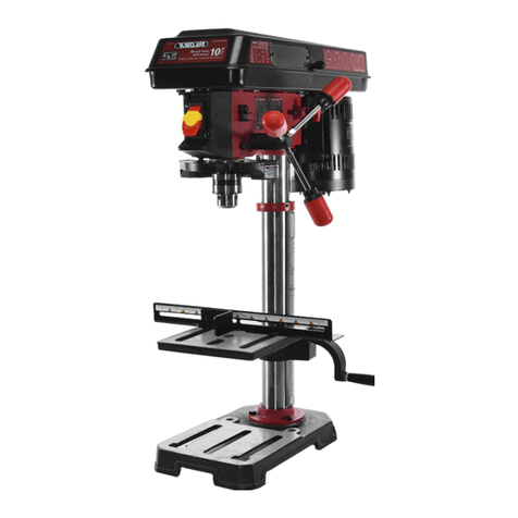
KNOVA KN DP-2000N User manual

KN DP-2000N
Bench drill press
8
”
Taladro de columna de banco
(203.2 mm)

Safety guidelines - denitions ............................................. 1
Product specications KN DP-2000N ................................. 1
General power tool safety rules .......................................... 1
Important safety instruction for drill press .......................... 2
Electrical requirements and safety ...................................... 4
Glossary of terms ................................................................ 5
Symbols ............................................................................... 6
Carton contents ................................................................... 6
Functional description ......................................................... 7
Tools needed for assembly ................................................ 8
Assembly and adjustments ................................................ 8
Operating instructions ....................................................... 12
Maintenance ...................................................................... 14
Troubleshooting ................................................................. 15
Parts list ............................................................................ 16
Exploded view .................................................................... 17
Notes ................................................................................. 36
PRODUCT SPECIFICATIONS KN DP-2000N
GENERAL POWER TOOL SAFETY RULES
TABLE OF CONTENTS
1
SAFETY GUIDELINES - DEFINITIONS
It is important for you to read and understand this manual. The information it contains relates to protecting YOUR SAFETY
and PREVENTING PROBLEMS. The symbols below are used to help you recognize this information.
DANGER
Indicates an imminently hazardous situation which, if not avoided, will result in death or serious injury.
WARNING
Indicates a potentially hazardous situation which, if not avoided, could result in death or serious injury.
CAUTION
Indicates a potentially hazardous situation which, if not avoided, may result in minor or moderate injury.
NOTICE: Used without the safety alert symbol indicates potentially hazardous situation which, if not avoided, may
result in property damage.
WARNING
• Read all safety warnings and all instructions. Failure
to follow the warnings and instructions may result in
electric shock, re and/or serious injury.
• People with electronic devices, such as
pacemakers, should consult their physician(s)
before using this product. Operation of electrical
equipment in close proximity to a heart pacemaker
could cause interference or failure of the pacemaker.
SAVE ALL WARNINGS AND INSTRUCTIONS FOR
FUTURE REFERENCE
The term “power tool” in the warnings refers to your
mains-operated (corded) power tool or battery-operated
(cordless) power tool.
Work area safety
• Keep work area clean and well lit. Cluttered or dark
areas invite accidents.
• Do not operate power tools in explosive atmospheres,
such as in the presence of ammable liquids, gases or
dust. Power tools create sparks which may ignite the
dust or fumes.
• Keep children and bystanders away while operating a
power tool. Distractions can cause you to lose control.
Electrical safety
• Power tool plugs must match the outlet. Never modify
the plug in any way. Do not use any adapter plugs with
earthed (grounded) power tools. Unmodied plugs and
matching outlets will reduce risk of electric shock.
• Avoid body contact with earthed or grounded surfaces,
such as pipes, radiators, ranges and refrigerators.
There is an increased risk of electric shock if your body is
earthed or grounded.
• Do not expose power tools to rain or wet conditions.
Water entering a power tool will increase the risk of
electric shock.
• Do not abuse the cord. Never use the cord for carrying,
pulling or unplugging the power tool. Keep cord away
from heat, oil, sharp edges or moving parts. Damaged
or entangled cords increase the risk of electric shock.
Motor: 1/3 HP, 120 V ~, 60 Hz
Speeds: 5 (750 - 3 200 RPM)
Morse cone: JT 33
Chuck size: 1/2” (13 mm)
Table tilt: 45º L & 45º R
Spindle travel: 2” (50.8 mm)
Distance from
spindle to column: 4” (101.6 mm)
Column diameter: 1-13/16” (46 mm)
Table size: 6-15/32” x 6-15/32”
Base size: 10-7/8” x 7”
Overall height: 23” (584.2 mm)
Weight: 31.75 / 34.4 lbs
Laser guide: Yes

2
GENERAL POWER TOOL SAFETY RULES
• When operating a power tool outdoors, use an
extension cord suitable for outdoor use. Use of a cord
suitable for outdoor use reduces the risk of electric shock.
• If operating a power tool in a damp location is
unavoidable, use a residual current device (RCD)
protected supply. Use of an RCD reduces the risk of
electric shock.
Personal safety
• Stay alert, watch what you are doing and use common
sense when operating a power tool. Do not use a power
tool while you are tied or under the inuence of drugs,
alcohol or medication. A moment of inattention while
operating power tools may result in serious personal injury.
• Use personal protective equipment. Always wear eye
protection. Protective equipment such as dust mask,
nonskid safety shoes, hard hat, or hearing protection used
for appropriate conditions will reduce personal injuries.
• Prevent unintentional starting. Ensure the switch is in
the off-position before connecting to power source
and/or battery pack, picking up or carrying the tool.
Carrying power tools with your nger on the switch or
energizing power tools that have the switch on invites
accidents.
• Remove any adjusting key or wrench before turning the
power tool on. A wrench or a key left attached to a
rotating part of the power tool may result in personal
injury.
• Do not overreach. Keep proper footing and balance at
all times. This enables better control of the power tool in
unexpected situations.
• Dress properly. Do not wear loose clothing or jewelry.
Keep your hair, clothing and gloves away from moving
parts. Loose clothes, jewelry or long hair can be caught
in moving parts.
• If devices are provided for the connection of dust
extraction and collection facilities, ensure these are
connected and properly used. Use of dust collection can
reduce dust-related hazards.
• Do not let familiarity gained from frequent use of tools
allow you to become complacent and ignore tool safety
principles. A careless action can cause severe injury
within a fraction of a second.
Power tool use and care
• Do not force the power tool. Use the correct power tool
for your application. The correct power tool will do the
job better and safer at the rate for which it was designed.
• Do not use the power tool if the switch does not turn it
on and off. Any power tool that cannot be controlled with
the switch is dangerous and must be repaired.
• Disconnect the plug from the power source and/or
remove the battery pack, if detachable, from the power
tool before making any adjustments, changing
accessories, or storing power tools. Such preventive
safety measures reduce the risk of starting the power
tool accidentally.
• Store idle power tools out of the reach of children and
do not allow persons unfamiliar with the power tool or
these instructions to operate the power tool. Power
tools are dangerous in the hands of untrained users.
• Maintain power tools and accessories. Check for
misalignment or binding of moving parts, breakage of
parts and any other condition that may affect the
power tool’s operation. If damaged, have the power
tool repaired before use. Many accidents are caused by
poorly maintained power tools.
• Keep cutting tools sharp and clean. Properly maintained
cutting tools with sharp cutting edges are less likely to
bind and are easier to control.
• Use the power tool, accessories and tool bits etc. in
accordance with these instructions, taking into account
the working conditions and the work to be performed.
Use of the power tool for operations different from those
intended could result in a hazardous situation.
• Keep handles and grasping surfaces dry, clean and free
from oil and grease. Slippery handles and grasping
surfaces do not allow for safe handling and control of the
tool in unexpected situations.
Service
• Have your power tool serviced by a qualied repair
person using only identical replacement parts. This will
ensure that the safety of the power tool is maintained.
IMPORTANT SAFETY INSTRUCTION FOR DRILL PRESS
WARNING
For your own safety, do not try to use your drill press
or plug it in until it is completely assembled and
installed according to the instructions, and until you
have read and understood this instruction manual.
• YOUR DRILL PRESS MUST BE BOLTED securely to a
workbench. In addition, if there is any tendency for your
drill press to move during certain operations, bolt the
workbench to the oor.
• THIS DRILL PRESS is intended for use in dry conditions,
indoor use only.
• WEAR EYE PROTECTION. USE a face or dust mask
along with safety goggles if drilling operation is dusty.
USE ear protectors, especially during extended periods
of operation.
• DO NOT wear gloves, neckties, or loose clothing.
• DO NOT try to drill material too small to be securely held.
• ALWAYS keep hands out of the path of a drill bit. Avoid
awkward hand positions where a sudden slip could cause
your hand to move into the drill bit.
• DO NOT install or use any drill bit that exceeds 175 mm
(7 in.) in length or extends 150 mm (6 in.) below the chuck
jaws. They can suddenly bend outward or break.
• DO NOT USE wire wheels, router bits, shaper cutters,
circle (y) cutters, or rotary planers on this drill press.
• WHEN cutting a large piece of material, make sure it is
fully supported at the table height.
• DO NOT perform any operation freehand. ALWAYS hold
the workpiece rmly against the table so it will not rock or
twist. Use clamps or a vise for unstable workpieces.
SAVE THIS INSTRUCTION
3
IMPORTANT SAFETY INSTRUCTION FOR DRILL PRESS
• MAKE SURE there are no nails or foreign objects in the
part of the workpiece to be drilled.
• CLAMP THE WORKPIECE OR BRACE IT against the
left side of the column to prevent rotation. If it is too
short or the table is tilted, clamp it solidly to the table.
• IF THE WORKPIECE overhangs the table such that it
will fall or tip if not held, clamp it to the table or provide
auxiliary support.
• SECURE THE WORK. Use clamps or a vise to hold the
work when practical. It’s safer than using your hand and
it frees both hands to operate tool.
• WHEN using a drill press vise, always fasten to the table.
• MAKE SURE all clamps and locks are rmly tightened
before drilling.
• SECURELY LOCK THE HEAD and table support to the
column, and the table to the table support before
operating the drill press.
• NEVER turn your drill press on before clearing the table
of all objects (tools, scraps of wood, etc.)
• BEFORE STARTING the operation, jog the motor switch
to make sure the drill bit does not wobble or vibrate.
• LET THE SPINDLE REACH FULL SPEED before
starting to drill. If your drill press makes an unfamiliar
noise or if it vibrates excessively, stop immediately, turn
the drill press off and unplug. If do not restart the unit
until the problem is corrected.
• DO NOT perform layout assembly or set up work on the
table while the drill press is in operation.
• USE THE RECOMMENDED SPEED for any drill press
accessory and for different workpiece material. READ
THE INSTRUCTIONS that come with the accessory.
• WHEN DRILLING large diameter holes, clamp the
workpiece rmly to the table. Otherwise, the bit may grap
and spin the workpiece at high speeds. DO NOT USE
y cutters or multiple-part hole cutters, as they can come
apart or become unbalanced in use.
• MAKE SURE the spindle has come to a complete stop
before touching the workpiece.
• TO AVOID INJURY from accidental starting, always turn
the switch “OFF” and unplug the drill press before
installing or removing any accessory or attachment or
making any adjustment.
• KEEP GUARDS IN PLACE and in working order.
• USE ONLY THE SELF-EJECTING TYPE CHUCK KEY
as provided with the drill press.
WARNING
TO AVOID BEING PULLED INTO THE SPINNING
TOOL - Tie back long hair and roll long sleeves above
elbows. Drum sanders must never be operated on this
drill press at a speed greater than the speed rating of
the drum sander.
WARNING
Feed workpiece into a sanding drum or other approved
accessory, against the direction of rotation.
WARNING
A kickback occurs when workpiece suddenly binds on
the cutting edge of the tool and the workpiece is thrown
by the cutter in the direction of the cutter’s rotation.
This can cause serious injury.
WARNING
WARNING
Do not allow familiarity (gained from frequent use of
your drill press) to become commonplace. Always
remember that a careless fraction of a second is
sufcient to inict severe injury.
Some dust created by power sanding, sawing,
grinding, drilling, and other construction activities
contains chemicals known to the State of California
to cause cancer, birth defects or other reproductive
harm. Some examples of these chemicals are:
• lead from lead-based paints,
• crystalline silica from bricks and cement and other
masonry products, and
• arsenic and chromium from chemically-treated
lumber.
Your risk from these exposures varies, depending on
how often you do this type of work. To reduce your
exposure to these chemicals: work in a well ventilated
area, and work with approved safety equipment, such
as those dust masks that are specially designed to lter
out microscopic particles.
• Avoid prolonged contact with dust from power
sanding, sawing, grinding, drilling, and other
construction activities. Wear protective clothing
and wash exposed areas with soap and water.
Allowing dust to get into your mouth, eyes, or lay on
the skin may promote absorption of harmful
chemicals.
WARNING
Use of this tool can generate and/or disperse dust,
which may cause serious and permanent respiratory
or other injury. Always use NIOSH/OSHA approved
respiratory protection appropriate for the dust
exposure. Direct particles away from face and body.
• Wear appropriate hearing protection during use.
Under some conditions and duration of use, noise
from this product may contribute to hearing loss.
WARNING
ALWAYS use safety glasses. Everyday eye glasses
are NOT safety glasses. Also use face or dust mask
if cutting operation is dusty. ALWAYS WEAR
CERTIFIED SAFETY EQUIPMENT:
• ANSI Z87.1 eye protection (CAN/CPA Z94.3),
• ANSI S12.6 (S3.19) hearing protection,
• NIOSH/OSHA respiratory protection.
ADDITIONAL SAFETY RULES FOR LASER
Laser radiation, avoid direct eye exposure, serious eye injury
can result.
• Do not use optical tools such as a telescope or transit to
view the laser beam.
• Position the laser so unintentional eye contact will be
avoided.

4
IMPORTANT SAFETY INSTRUCTION FOR DRILL PRESS
• Do not operate the laser around children or allow children
to operate the laser / power tool.
• Do not disassemble. Modifying the product in any way
can increase the risk of laser radiation. Use of controls or
adjustments or performance of procedures other than
those specied in this manual may result in hazardous
laser radiation exposure.
• Do not operate in explosive atmospheres, such as in the
presence of ammable liquids, gases, or dust.
• Store idle product out of reach of children and other
untrained persons. Lasers / power tools are dangerous
in the hands of untrained users.
• Use only accessories that are recommended by the
manufacturer for your model. Accessories that may be
suitable for one laser / power tool, may create a risk of
injury when used on another laser / power tool.
• Repairs and servicing MUST be performed by a qualied
repair facility. Repairs performed by unqualied
personnel could result in serious injury.
• Do not remove or deface warning labels. Removing labels
increases the risk of exposure to radiation.
WARNING
LASER RADIATION. AVOID DIRECT EYE
EXPOSURE. Do not stare into the laser light source.
Never aim light at another person or object other than
the work piece. Laser light can damage your eyes.
WARNING
LASER RADIATION. Never aim the beam at a work
piece with a reective surface. Bright shiny reective
sheet steel or similar reective surfaces are not
recommended for laser use. Reective surfaces could
direct the beam back toward the operator.
WARNING
DO NOT use tinted glasses to enhance the laser light.
Tinted glasses will reduce overall vision for the
application and interfere with the normal operation of
the tool.
• For indoor use only.
• This product is intended for use in a temperature range
of 41°F (5°C) - 104°F (40°C).
ELECTRICAL REQUIREMENTS AND SAFETY
POWER SUPPLY AND MOTOR SPECIFICATIONS
WARNING
To avoid electrical hazards, re hazards, or damage
to the tool, use proper circuit protection. Use a
seperate electrical circuit for your tool. Your drill
press is wired at the factory for 120 V operation.
Connect to a 120 V, 2.3 Amp circuit and use a
2.3 Amp time delay fuse or circuit breaker. To avoid
shock or re, if power cord is worn, cut, or damaged
in any way, have it replaced immediately.
IN THE EVENT OF A MALFUNCTION OR BREAKDOWN,
grounding provides a path of least resistance for electric
currents and reduces the risk of electric shock. This tool
is equipped with an electrical cord that has an
equipment-grounding conductor and a grounding plug. The
plug must be plugged into a matching receptacle that is
properly installed and grounded in accordance with all local
codes and ordinances.
DO NOT MODIFY THE PLUG PROVIDED.
If it will not t the receptacle, have the proper receptacle
installed by a qualied electrician.
IMPROPER CONNECTION of the equipment grounding
conductor can result in risk of electric shock. The conductor
with the green insulation (with or without yellow stripes) is
the equipment grounding conductor. If repair or replacement
of the electrical cord or plug is necessary, do not connect the
equipment grounding conductor to a live terminal.
CHECK with a qualied electrician or service person if you
do not completely understand the grounding instructions, or if
you are not certain the tool is properly grounded.
USE only 3-wire extension cords that have three-pronged
grounding plugs with three- pole receptacles that accept
the tool’s plug. Repair or replace damaged or worn cords
immediately.
GROUNDING INSTRUCTIONS
WARNING
This tool must be grounded while in use to protect the
operator from electrical shock.
Use a separate electrical circuit for your tool. This circuit must
not be less than #18 wire and should be protected with a
2.3 Amp time lag fuse. Before connecting the motor to the
power line, make sure the switch is in the off position and the
electric current is rated the same as the current stamped on
the motor nameplate. Running at a lower voltage will damage
the motor.
GUIDELINES FOR EXTENSION CORDS USE THE
PROPER EXTENSION CORD.
Make sure your extension cord is in good condition. Use an
extension cord heavy enough to carry the current your
product will draw. An undersized cord will cause a drop in line
voltage resulting in loss of power, overheating and burning
out of the motor. The table below shows the correct size to
use depending on cord length and nameplate ampere rating.
If in doubt, use the next heavier gauge. The smaller the gauge
number, the heavier the cord.
Make sure your extension cord is properly wired and in good
condition. Always replace a damaged extension cord or have
it repaired by a qualied technician before using it. Protect
your extension cords from sharp objects, excessive heat and
damp or wet areas.
MINIMUM GAUGE FOR EXTENSION CORDS (AWG)
(When using 120 volts only)
Ampere Rating Total length of Cord
More than
Not more than
25ft. 50ft. 100ft. 150ft.
0 6 18 16 16 14
6 10 18 16 14 12
10 12 16 16 14 12
12 16 14 12
Not Recommended
AWG-American wire gauge

5
ELECTRICAL REQUIREMENTS AND SAFETY
WARNING
This tool is for indoor use only. Do not expose to rain
or use in damp locations.
This tool is intended for use on a circuit that has a
receptacle like the one illustrated in Fig. 1. Fig. 1 shows
a three-pronged electrical plug and receptacle that has
a grounding conductor. If a properly grounded
receptacle is not available, an adapter (Fig. 2) can be
used to temporarily connect this plug to a two-contact
grounded receptacle. The adapter (Fig. 2) has a rigid
lug extending from it that MUST be connected to a
permanent earth ground, such as a properly grounded
receptacle box.
WARNING
In all cases, make certain the receptacle is properly
grounded. If you are not sure, have a qualied
electrician check the receptacle.
Fig. 1 Three-pronged plug
Grounding prong
Properly grounded
Grounding lug
Adapter
Make sure this is
connected to a
known ground
Pronged receptacle
Fig. 2
GLOSSARY OF TERMS
BASE – Supports drill press. For additional stability, holes are
provided in the base to bolt drill press to the oor. (See
“ADDITIONAL SAFETY RULES FOR DRILL PRESSES”.)
BACKUP MATERIAL – A piece of scrap wood placed
between the workpiece and table. The backup board prevents
wood in the workpiece from splintering when the drill passes
through the backside of the workpiece. It also prevents
drilling into the table top.
PULLEY COVER – Covers the pulleys and belt during
operation of the drill press.
BELT TENSION – Refer to the “Assembly” Section,
“Installing and Tensioning Belt.”
BELT TENSION LOCK KNOBS – Tightening the knobs locks
the motor bracket support, maintaining correct belt distance
and tension.
BEVEL SCALE – Shows degree of table tilt for bevel
operations. The scale is mounted on the side of the arm.
CHUCK – Holds a drill bit or other recommended accessory
to perform desired operations.
CHUCK KEY – A self-ejecting chuck key which will pop out
of the chuck when you let go of it. This action is designed to
help prevent throwing of the chuck key from the chuck when
the power is turned “ON.” Do not use any other key as a
substitute; order a new one if damaged or lost.
COLUMN ASSEMBLY – Connects the head, table, and
base on a one piece tube for easy alignment and movement.
Mounts to base.
COLUMN SUPPORT – Supports the column and provides
mounting holes for the column to the base.
DEPTH SCALE STOP NUTS – Lock the spindle to a selected
depth.
DEPTH SCALE – Indicates depth of hole being drilled.
DRILL BIT – The cutting tool used in the drill press to make
holes in a workpiece.
ON/OFF SWITCH – Has locking feature. This feature is
intended to help prevent unauthorized and possible
hazardous use by children and others. Insert the key into the
switch to turn the drill press on.
DRILLING SPEED – Changed by placing the belt in any of
the steps (grooves) in the pulleys. See the Spindle Speed
Chart inside belt guard.
HEX HEAD LOCK SCREWS – Locks the head to the
column. ALWAYS lock the head in place while operating
the drill press.
REVOLUTIONS PER MINUTE (R.P.M.) – The number of
turns completed by a spinning object in one minute.
SPINDLE SPEED – The R.P.M. of the spindle.
SPRING CAP – Adjusts the quill return spring tension.
TABLE SUPPORT LOCK – Tightening locks the table
support to the column. Always have it locked in place while
operating the drill press.
TABLE – Provides a working surface to support the
workpiece.
TABLE BEVEL LOCK – Locks the table in any position from
0° to 45°.
TABLE LOCK HANDLE – Locks the table after it is rotated
to various positions and heights.
WORKPIECE – Material being drilled.
Three-pronged
receptacle

SYMBOLS
6
Your power tool and its Instruction Manual may contain “WARNING ICONS” (a picture symbol intended to alert you to,
and/or instruct you how to avoid a potentially hazardous condition). Understanding and heeding these symbols will help you
operate your tool better and safer. Shown below are some of the symbols you may see.
SAFETY ALERT:
Precautions that
involve your safety.
WEAR EYE
PROTECTION:
Always wear safety
goggles or safety
glasses with side shields.
WEAR A MASK:
Always wear a
face mask or dust mask.
WEAR HEARING PROTECTION:
To reduce the risk of induced hearing
loss, always wear a hearing protection.
READ AND UNDERSTAND
INSTRUCTION MANUAL:
To reduce the risk of injury, user and all
bystanders must read and understand
instruction manual before using this product.
KEEP HANDS AWAY
FROM BLADE:
Failure to keep your
hands away from the
blade will result in
serious personal injury.
SUPPORT AND
CLAMP WORK
PROHIBITION
CARTON CONTENTS
1) Carefully remove the drill press from the carton. With the help of an assistant, place the head assembly on a secure surface
and examine it carefully.
2) Separate and layout all of the parts. Carefully check them according to the diagram below.
WARNING
If any part is missing or damaged, please do not plug in or use the drill press until replacements have been obtained.
Base
Head assembly
Table assembly Feed handles Table lock
handle
Column assembly
Hex bolts
3 mm & 4 mm
hex keys
Self-ejecting
chuck key
Chuck

FUNCTIONAL DESCRIPTION
7
1. Pulley cover
2. Depth stop nuts
3. Depth scale pointer
4. Depth scale
5. Spindle
6. Table
7. Bevel lock bolt
8. Base
9. Column assembly
10. Table assembly
11. Spring cap (Quill return coil/spring)
12. Motor
13. Laser guides
14. Belt tension lock knob
15. Hex head lock screws
16. Feed handles
17. Bevel scale
18. Table lock handle
19. Mounting holes
20. Chuck
21. ON/OFF switch with safety key
22. Chuck key holder
23. Laser ON/OFF switch
24. V-belt
25. Spindle pulley
26. Motor pulley
123
4
5
6
7
13
12
11
10
9
8
22 23
14
15
16
17
18
19
20
21
26
25
24

8
TOOLS NEEDED FOR ASSEMBLY
Slotted screwdriver
Phillips screwdriver
10, 13 & 16 mm wrench
NOT SUPPLIEDNOT SUPPLIED NOT SUPPLIED
Adjustable wrench
Combination square
Block of wood
Hammer or
rubber mallet
SUPPLIED
3 mm hex key
4 mm hex key
ASSEMBLY AND ADJUSTMENTS
WARNING
• For your own safety, never connect plug to power
source outlet until all assembly steps are complete
and you have read and understood the safety and
operating instructions.
• The drill press is a heavy power tool and should be
lifted with the help of two PEOPLE OR MORE to
safely assemble it.
1
3
2
Fig. A
ASSEMBLY (FIG. B)
• Install the table lock
handle (3) in the threaded
hole (4) located in the back
of the table assembly (1).
• Slide the table assembly (1) down along the column
assembly (2) to desired working height, and tighten
the table lock
handle (3) to
secure the table
in place.
1
2
3
4
Fig. B
INSTALLING THE HEAD (FIG. C)
WARNING
2
3
Fig. C
INSTALLING FEED HANDLES (FIG. D)
• Screw the three feed handles (1) into the holes (2)
on the hub assembly (3) and tighten.
ASSEMBLING COLUMN TO BASE (FIG. A)
• Position the base (1) on a at work surface.
• Place the column assembly (2)
on the base (1), aligning
the three mounting holes
to the base.
• Locate the three hex bolts (3)
from the loose parts bag.
• Place a bolt in each hole through
the column support and thread
into the base. Tighten with
a 13 mm wrench.
• Carefully lift the head (1) above the column assembly (2)
and slide it down the column as far as it will go.
• Align the head (1) with the base.
• Tighten the two head
locking screws (3)
with a 4 mm
hex key.
The drill press head is heavy and should be lifted with
the help of two PEOPLE to safely assemble the drill
press head on the column.
1
1
3
2
Fig. D

ASSEMBLY AND ADJUSTMENTS
9
INSTALLING THE CHUCK (FIG. E, F)
WARNING
• Before any assembly of the chuck to the drill press
head, clean all mating surfaces with a non-petroleum
based product. Any oil or grease used in the packing
of these parts must be removed otherwise the
chuck may come loose during operation.
2
1
• To avoid injury from an accidental start, ALWAYS make
sure the power switch is in the “OFF” position, the
switch key is removed, and the plug is not connected to
the power source outlet before removing or installing
the chuck.
• Clean out the tapered hole in the chuck (1) with a clean
cloth and a non petroleum based product. Wipe clean all
oil reside and any dirt or grime thoroughly.
• Clean tapered surfaces on the spindle (2) in the same
manner as above.
NOTE: Make sure there are no foreign particles sticking
to the surfaces. The slightest piece of dirt or oil reside on
any of these surfaces will prevent the chuck from seating
properly, and cause the chuck and bit wobble.
• Open the jaws of the chuck (1)
by rotating the chuck sleeve clockwise.
To prevent damage, make sure the jaws
are completely retracted into the chuck.
• Unlock the table lock handle and slide
down the table away from the bottom
of the chuck.
• Insert the chuck (1) onto
the spindle (2), pushing
upwards all the way.
• Using a rubber mallet or a hammer
with a block of wood, tap the chuck
onto the spindle rmly. (Fig. F)
Fig. E
CAUTION
RISK OF PROPERTY DAMAGE. To avoid damage to
the chuck, NEVER drive the chuck on the spindle with
a metal hammer.
Fig. F
REMOVING THE CHUCK
• Turn the feed handles
to lower the chuck
to the lowest position.
• Place a ball joint separator
(not shown) above the chuck
and tap it lightly with a
hammer or rubber mallet
to cause the chuck to
drop from the spindle.
NOTE: Never hit the chuck directly with the hammer or
rubber mallet.
NOTE: The avoid possible damage to the chuck, raise the
jaws all the way rst and be prepared to catch the chuck
as it falls.
CHUCK KEY STORAGE (FIG. G)
• Storage holder (1) for the chuck key (2) is located on
the right side of the drill press.
Fig. G
12
MOUNTING DRILL
PRESS TO WORK
SURFACE (FIG. H)
• If mounting the drill press to a workbench,
a solid wood bench is preferred over a
plywood board to reduce noise and vibration.
• Holes should be pre-drilled through
the supporting surface.
NOTE: The hardware to mount this drill press are
NOT supplied with the tool. The hardware as shown
in the illustration below should be used:
1. Drill press base
2. Bolt
3. Flat washer
4. Rubber washer
5. Worksurface
6. Flat washer
7. Lock washer
8. Hex nut
9. Jam nut
Fig. H
1
5 6
89
7
2
3
4
ADJUSTMENT INSTRUCTIONS
NOTE: All the adjustments for the operation of the drill press
have been completed at the factory. Due to normal wear and
use, some occasional readjustments may be necessary.
BEVEL DRILLING (FIG. I)
NOTE: A bevel scale has been included to measure
approximate bevel angles. If precision is necessary, a square
or other measuring tool should be used to position the table.
NOTE: The table is not shown
in Fig. I for clarity of illustration.
• Loosen the bevel
lock bolt (1) with
an adjustable wrench.
• Tilt the table to
the desired angle, using
the bevel scale (2) as a
basic guide.
• Tighten the bevel
lock bolt (1).
WARNING
To avoid injury from an accidental start, ALWAYS
make sure the switch is in the “OFF” position, the
switch key is removed, and the plug is not connected
to the power source outlet before making belt
adjustments.
2
1
Fig. I

ASSEMBLY AND ADJUSTMENTS
10
SPINDLE / QUILL (FIG. J)
Rotate the feed handles counterclockwise to lower spindle to
its lowest position. Hold the chuck and move it front to back.
If there is excessive play, proceed with the following
adjustments:
• Loosen the lock nut (1) located on the right side of the
drill press, using a 13 mm wrench.
• Turn the screw (2) clockwise to eliminate the play, using
a slotted screwdriver, but without obstructing the upward
movement of the the spindle. (A little play in the spindle
is normal.)
• Tighten the lock
nut (1).
QUILL RETURN SPRING (FIG. K)
The quill return spring may need adjustment if the quill return
speed is too rapid or too slow. This spring is located on the
left side of the drill head.
• Lower the table for additional clearance.
• Place a screwdriver in the lower front notch (1) of the
spring cap (2). Hold it in place while loosening and
removing only the outer jam nut (3), using a 16 mm
wrench.
• With the screwdriver still engaged in the notch, loosen the
inner nut (4) just until the notch (5) disengages from the
boss (6) on the drill press head.
NOTE: DO NOT REMOVE THIS INNER NUT, because
the spring will forcibly unwind.
• Carefully turn the spring cap (2) counterclockwise with
the screwdriver, engaging the next notch.
• Lower the quill to the lowest position by rotating the feed
handle in a counterclockwise direction while holding the
spring cap (2) in position.
• If the quill moves up and down as you desire, tighten the
inner nut (4) close against the spring cap with a
adjustable wrench. If too loose, repeat above steps 3
through 5 to tighten. If too tight, reverse steps 4 and 5.
• Secure the outer nut (3) against the inner nut with
the wrench.
NOTE: DO NOT OVERTIGHTEN and restrict quill
movement.
1
2
Fig. J
2
Fig. K
56
341
BELT TENSION (FIG. L)
WARNING
To avoid injury from an accidental start, ALWAYS
make sure the switch is in the “OFF” position, the
switch key is removed, and the plug is not connected
to the power source outlet before making belt
adjustments.
• Open the pulley cover.
• To unlock the belt tension, turn the belt tension lock
knob (1) on the right side of the drill press head
counterclockwise.
• Pull the motor (2) toward the front of the drill press to
loosen the belt tension.
• Position the belt on the correct pulley steps for
the desired speed.
• Push the motor away from the drill press head until the
belt is properly tensioned.
NOTE: Belt tension is correct if the belt deects
approximately 1/2 inch when pressed at its center.
• Tighten the belt tension lock knob (1) to secure the motor
in position. Close pulley cover.
1
2
Fig. L
LASER ADJUSTMENT (FIG. M, N, O)
NOTE: The laser assembly has been installed and preset at
the factory. However, it should be checked and adjusted
before operating the drill press. It should also be re-checked
periodically, as constant machine vibration may cause it to
become misaligned.
• Take off the cover (1) by removing the screws (2) using a
Phillips Screwdriver to access the laser assembly. (Fig. M)
• Take a length of board (6) and draw a perpendicular
line (7) on one side of board using a square. (Fig. N)
• Place a small drill bit (8) into the chuck (9), then place the
board (6) on the table. The board edge against the drill
bit (8) with the marked line side toward the back of the
drill press.
NOTE: The table should be in horizontal position and
locked. Verify that the marked line (7) is perpendicular
to the table.
• Connect power to the drill press, and turn on the laser by
pressing the button at the front of the drill press head.
WARNING
A laser light is radiated when the laser guide is turned
on. Avoid direct eye contact. Remove the safety key
from the main on/off switch before making an
adjustment to the laser guides. (see page 12
ON/OFF SWITCH PANEL for more details)

ASSEMBLY AND ADJUSTMENTS
11
1
Fig. M
3
4
5
2
10
8
9
11
6
7
10
Fig. N
Vertical Alignment (Fig. M, N)
• Loosen the hex screws (3) using a 3 mm hex wrench,
manually rotate the laser adjusting knob (5) and move
the board from side to side as required until the laser
beam (10) lines up with the marked line (7). Keep
adjusting until the laser beam (10) and the marked line (7)
are aligned. Then carefully tighten the hex screws (3).
• Adjust the other laser beam (11) in the same manner.
Two parallel laser beams (10, 11) should look like
the right side drawing in Fig. N.
NOTE: The distance between the laser beams will vary
with board thickness; however, the laser beams must be
parallel.
Crosshairs Alignment (Fig. M, O)
• Place a board (12) at on the table. Do not allow the board
to move from this position; use clamps if needed. Bring
the bit down until it leaves a slight perforation in the
board; then raise it back up.
• Using a 10 mm wrench, slightly loosen the nut (4) so
the laser beam crosses the perforation (13).
Tighten the nut (4).
• Adjust the other laser assembly in the same manner until
the laser beams form crosshairs (14) exactly over
the perforation (13) on the board (12).
• Re-check the vertical alignment
to ensure that the laser
beams did not shift during
the tightening process.
The drilling hole
is now at the center
of crosshairs for
accurate drilling.
• Replace the covers (1)
with the screws (2)
over the laser
assembly on
each side.
14
12
13
Fig. O
LASER LABEL (FIG. P)
For your convenience and safety, the following labels are
on your laser.
The label (1) on your laser may include the following symbols.
(Fig. P)
V ................................................................................. volts
mW .......................................................................... milliwatts
nm ............................................... wavelength in nanometers
II .................................................................... Class Il Laser
Laser Aperture Label (2): AVOID
EXPOSURE: Laser radiation is emitted from this aperture.
(Fig. P)
2
1
2
Fig. P

OPERATING INSTRUCTIONS
12
BASIC DRILL PRESS OPERATIONS
SPEEDS AND BELT PLACEMENT (FIG. Q)
This drill press has ve operating speeds. Please see the
chart below for each speed and the placement of the belt to
obtain those speeds. This chart is also put on the inside of
pulley cover for reference.
WARNING
• To avoid possible injury, keep the pulley cover
closed while tool is in operation.
• Never connect the plug to the power source outlet
until all installations and adjustments are completed
and you have read and understood the safety and
operation instructions.
BELT: A-1
BELT: B-2
BELT: C-3
BELT: D-4
BELT: E-5
DRILLING SPEED TABLE (rpm)
Wood Alum., Zinc, Brass Iron, Steel
Material
1/16
1/8
3/16
1/4
5/16
3/8
1/2
3,200
2,100
1,500
1,100
750
3,200
2,100
1,500
1,100
Fig. Q
Drill bit
diameter
(Inches)
3,200
2,100
ON / OFF SWITCH PANEL (FIG. R)
The “ON / OFF” switch has a removable, safety key. With the
key removed from the switch, unauthorized and hazardous
use by children and others is minimized.
• To turn the drill press “ON,” insert the key (1) into the slot
of the switch (2), and move the switch upward to the “ON”
position.
• To turn the drill press “OFF,” move the switch downward.
• To lock the switch in the OFF position, grasp the sides of
the safety switch key, and pull it out.
• With the safety key removed, the switch will not operate
to power the drill press on.
• If the safety key is removed while the drill press is running,
it can be turned “OFF” but cannot be restarted without
inserting the safety key.
• Your tool is equipped with a laser guide. The laser beam
will enable you to preview the drill bit path on the
workpiece to be drilled before you begin your operation.
To turn the laser “ON,” press the rocker switch (3) to
the “ON” position. To turn the laser “OFF,” press the
rocker switch to the “OFF” position.
• Never leave the drill press unattended. Turn the power
switch “OFF” and wait until it comes to a complete stop,
and remove the safety key to prevent unauthorized starts.
WARNING
ALWAYS lock the switch “OFF” when the drill press
is not in use. Remove the safety key and keep it in a
safe place. In the event of a power failure, blown fuse,
or tripped circuit breaker, turn the switch “OFF” and
remove the safety key, preventing an accidental
startup when power comes on.
3
Fig. R
1
2
INSTALLING DRILL BIT IN CHUCK (FIG. S)
• With the switch “OFF” and the safety key removed, open
the chuck jaws (1) using the chuck key (2). Turn the chuck
key counterclockwise to open the chuck jaws (1).
• Insert the drill bit (3) into the chuck far enough to obtain
maximum gripping by the jaws, but doesn’t touch the
spiral grooves (utes) of the drill bit when the jaws are
tightened.
• Make sure that the drill is centered in the chuck.
• Turn the chuck key clockwise to tighten the jaws.
WARNING
To avoid injury or accident by the chuck key ejecting
forcibly from the chuck
when the power is
turned “ON”, use only
the self-ejecting chuck
key supplied with this
drill press. ALWAYS
recheck and remove
the chuck key before
turning the power
“ON”. Place the chuck
key into its storage
holder when not
in use.
2
13
Fig. S

OPERATING INSTRUCTIONS
13
DRILLING TO A SPECIFIC DEPTH
Drilling a blind hole (not all the way through workpiece)
to a given depth can be done by two ways:
Workpiece method (Fig. T, U)
• Mark the depth (1)
of the hole on the side
of the workpiece. (Fig. T)
• With the switch “OFF”, bring
the drill bit (2)
down until the tip
is even with
the mark.
1
2
• Hold the feed handle
at this position.
• Spin the lower nut (3) down to contact the depth
stop lug (4). (Fig. U)
• Spin the upper nut (5) down and tighten against
the lower nut (3).
• The drill bit will now stop after traveling the distance
marked on the workpiece.
7
4
6
5
3
Fig. U
Depth scale method (Fig. U)
NOTE: With the chuck in
the upper position, the tip of
the drill bit must be just slightly
above the top of the workpiece.
• With the switch in the OFF
position, turn the feed handle
until the depth pointer (6) points
to the desired depth on
the depth scale (7)
and hold the feed
handle in that position.
• Spin the lower
nut (3) down to
contact the depth
stop lug (4).
• Spin the upper nut (5)
against the lower
nut (3) and tighten.
• The drill bit will stop
after traveling the distance
selected on the depth
scale (7).
DRILL A HOLE
Using a center punch or a sharp nail, make an indentation in
the workpiece where you want to drill. Turn on the laser
assembly and align the laser lines (x) with the indentation.
Turn the power switch on and pull down on the feed handles
with only enough effort to allow the drill to cut.
FEEDING TOO RAPIDLY might cause the belt or drill to slip,
tear the workpiece loose, or break the drill bit. When drilling
metal, it will be necessary to lubricate the tip of the drill bit
with metal drilling oil to prevent it from overheating.
BASIC OPERATING INSTRUCTIONS
To get the best results and minimize the likelihood of personal
injury, follow these instructions for operating your drill press.
Fig. T
WARNING
For your own safety, always observe the SAFETY
INSTRUCTIONS listed in this instruction manual
when operating the drill press.
POSITIONING THE TABLE AND WORKPIECE (FIG. V, W)
• Lock the table (1) to the column (2) at a position so
the tip of the drill bit (3) is just above the top of
the workpiece (4).
• ALWAYS place a BACK-UP MATERIAL (scrap wood)
on the table beneath the workpiece. This will prevent
splintering or heavy burring on the underside of
the workpiece. To keep the back-up material from
spinning, it MUST be positioned against the LEFT side
of the column.
• For a small piece that cannot be clamped to the table, use
a drill press vise (optional accessory).
WARNING
To prevent the workpiece or backup material from
being thrown while drilling, you MUST position the
workpiece against the LEFT side of the column. If the
workpiece or the backup
material is not long enough
to reach the column, clamp
them to the table to brace
the workpiece.
Failure to secure
the workpiece could
result in personal
injury.
4
1
2
3
Fig. V
WARNING
A drill press vise
MUST be clamped
or bolted to
the table to
avoid injury
from a spinning
workpiece, or
damaged vise
or bit parts.
TILTING THE TABLE (FIG. X)
• Loosen the bevel lock bolt (1) with an adjustable wrench.
• Tilt the table (2) to the desired angle and tighten
the bevel lock bolt.
WARNING
• To prevent injury, be sure to hold the table & table
arm assembly, so it will not swivel or tilt.
• To avoid injury from
spinning work or tool
breakage, always
clamp workpiece
and backup material
securely to the table
before operating
the drill press.
Fig. W
Fig. X
2
1
TRANSPORTING THE DRILL PRESS (FIG. Y)
WARNING
The drill press is very heavy and MUST be
transported with the help of 2 people or more,
to safely move it.

Fig. Y
1
2
14
OPERATING INSTRUCTIONS
• When transporting the drill
press, the table (1) and
head (2) should always be
locked in position. Refer
to the sections of
“INSTALLING
THE TABLE” and
“INSTALLING
THE HEAD” for details.
• Hold the table and motor
with two people as shown
in Fig. Y and then move
the drill press.
FREE WARNING LABEL
REPLACMENT:
If your warning labels
become illegible or are
missing, call: 01-800-70
KNOVA(56682) for a
free replacement.
MAINTENANCE
WARNING
For your own safety, turn the switch off and remove
the plug from the power source outlet before
maintaining or lubricating your drill press.
GENERAL MAINTENANCE
Frequently blow out dust and grit that accumulates in the
motor housing using compressed air.
A coat of automotive paste wax applied to the table and
column will help to keep the surface clean.
WARNING
ALWAYS use safety glasses. Everyday eyeglasses
are NOT safety glasses. Also use face or dust mask if
cutting operation is dusty.
ALWAYS WEAR CERTIFIED SAFETY EQUIPMENT:
• ANSI Z87.1 eye protection (CAN/CSA Z94.3),
• ANSI S12.6 (S3.19) hearing protection,
• NIOSH/OSHA/MSHA respiratory protection.
WARNING
To avoid shock or re hazard, if the power lead is
worn or cut in any way, replace it immediately.
LUBRICATION
Ball bearings in the drill press are packed with grease at
the factory and require no further lubrication.
Use only mild soap and a damp cloth to clean the tool. Never
let any liquid get inside the tool; never immerse any part of
the tool into a liquid.
IMPORTANT: To assure product SAFETY and RELIABILITY,
repairs, maintenance and adjustment (other than those listed
in this manual) should be performed by authorized service
centers or other qualied service organizations, always using
identical replacement parts.
To clean cast iron parts of rust, you will need the following
materials (not supplied): scouring pad, spray lubricant, can of
degreaser. Apply the spray lubricant and polish with surface
with the scouring pad. Degrease the surface, then apply
the protective product as an automotive paste wax.

15
TROUBLESHOOTING
POSSIBLE SOLUTIONPROBLEM POSSIBLE CAUSES
• Drill bit burns
• Run out of drill bit
point/drilled hole
not round.
• Wood splinters
on underside.
• Workpiece torn
loose from hand.
• Drill bit binds
in workpiece.
• Excessive drill bit
runout or wobble.
• Quill returns too
slow or too fast.
• Chuck will not stay
attached to spindle.
It falls off when
trying to install.
• Incorrect speed.
• Chips not coming out of hole.
• Dull drill bit.
• Feeding too slowly.
• Not lubricated.
• Grain in wood or lengths of cutting
flutes and/or angles not equal.
• Bent drill bit.
• No backup material under
workpiece.
• Not supported or clamped properly
• Workpiece pinching drill bit,
or excessive feed pressure.
• Improper belt tension.
• Bent drill bit.
• Worn bearings.
• Drill bit not properly installed
in chuck.
• Chuck not properly installed.
• Coil spring has improper tension.
• Dirt, grease, or oil on the tapered
inside surface of chuck or on the
spindle’s tapered surface.
• Change speed. See section
“SPEEDS AND BELT PLACEMENT”.
• Retract drill frequently to clear chips.
• Resharpen drill bit.
• Feed fast enough – allow drill to cut.
• Lubricate drill.
• Resharpen drill bit correctly.
• Replace drill bit.
• Use backup material. See section
“BASIC DRILL PRESS OPERATION”.
• Support workpiece or clamp it. See section
“BASIC DRILL PRESS OPERATION”.
• Support workpiece or clamp it. See section
“BASIC DRILL PRESS OPERATION”.
• Adjust tension. See section “BELT TENSION”.
• Replace drill bit.
• Replace bearings.
• Install drill bit properly. See section “BASIC DRILL
PRESS OPERATION” and “INSTALLING DRILL
BIT IN CHUCK”.
• Install chuck properly. See section
“INSTALLING THE CHUCK”.
• Adjust spring tension. See section
“QUILL RETURN SPRING”.
• Using a non-alcohol based cleaner, clean the tapered
surface of the chuck and spindle to remove all dirt,
grease and oil. See section
“INSTALLING THE CHUCK”.
• Noisy operation • Incorrect belt tension.
• Dry spindle.
• Loose spindle pulley.
• Loose motor pulley.
WARNING
To avoid injury from an accidental start, turn the switch OFF and always remove the plug from the power source
before making any adjustments.
• Adjust tension. See section “BELT TENSION”.
• Lubricate spindle.
• Check tightness of retaining nut on pulley,
and tighten if necessary.
• Tighten set screw in motor pulley.

2F7Z LASER WARNING LABEL 1
X8BX CHUCK KEY 1
X8BY CHUCK KEY HOLDER 1
X8BZ HEX WRENCH 3 MM 1
X8C1 CR. RE. PAN HD. SCREW M6 x 10 2
X8C2 LASER COVER 2
X8C8 BATTERY BOX DIPOLAR SPRING 1
X8C9 BATTERY BOX CATHODE SPRING 1
X8CA BATTERY BOX ANODE SRPING 1
X8CB LASER SWITCH 1
X8CC BATTERY BOX COVER 1
X8CD BATTERY BOX 1
X8CE FEED SHAFT 1
X8CF TABLE BRACKET 1
X8CG OIL CHOKING 1
X8CH FLAT WASEHR 1
X8CJ INSTURCTION MANUAL 1
X8CK HEX WRENCH 4 MM 1
X8CL RUBBER SLEEVE 2
X8CM CHUCK 1
X8CN POWER CORD 1
X8CR CR. RE. PAN HD. SCREW ST4.2 x 10 3
X8CS ON/OFF SWITCH 1
X8CT SWITCH COVER 1
X8CU CR. RE. PAN HD. SCREW M5 x 12 5
X8CV SWITCH BOX 1
X8CW CR. RE. PAN HD. SCREW M5 x 6 2
X8CX LOCK WASHER 2
X8CY HEX BOLT M5 1
X8CZ HEX SCREW M5 x 16 1
X8D0 PULLEY COVER HANDLE 1
X8D1 V-BELT 1
X8D2 MOTOR PULLEY 1
X8D3 SPINDLE PULLEY 1
X8D4 HEX BOLT 2
X8D5 CR. RE. PAN HD. SCREW M6 x 12 4
X8D6 CR. RE. PAN HD. SCREW M5 x 8 1
X8D7 CABLE CLAMP 1
X8D8 PULLEY COVER ASS’Y 1
PARTS LIST
When servicing use only KNOVA replacement parts. Use of any other parts many create a HAZARD or cause
product damage. Any attempt to repair or replace electrical parts on this Bench drill press may create a HAZARD
unless repair is done by a qualied service technician. Repair service is available at your nearest Knova Service Center.
To order replacement parts by phone, call 01-800-70 KNOVA(56682).
Description Qty.
I.D. No. Size
Description Qty.
I.D. No. Size
16
WARNING
X8D9 SPONGE WASHER 4
X8DA CR. RE. PAN HD. SCREW M5 x 12 1
X8DB CABLE RETAINING BLOCK 1
X8DC LOCK NUT M8 2
X8DD HEX BOLT M8 x 25 2
X8DE MOTOR ASS’Y 1
X8DF SHIFTER BOLT 1
X8DG COMPRESSION SPRING 1
X8DH MOTOR ROD CUSHION 1
X8DJ MOTOR ROD 1
X8DK DEPTH SCALE POINTER 1
X8DL HEX NUT M6 1
X8DM DEPTH SCALE BOLT 1
X8DN HEX NUT M5 1
X8DP CR. RE. PAN HD. SCREW M5 x 20 1
X8DQ HEX NUT M8 1
X8DR DEPTH SCALE BASE 1
X8DY HEX NUT M10 4
X8DZ SPRING CAP ASS’Y 1
X8E0 QUILL SET SCREW 1
X8E5 HEX SCREW M8 x 8 3
X8E6 SPRING PIN 1
X8E7 HEAD 1
X8E8 HEX BOLT M8 x 20 3
X8E9 TABLE LOCK HANDLE 1
X8EA HEX BOLT M12 x 25-8.8 1
X8EB WORK TABLE 1
X8EE BASE 1
X8EG SPEED DIAGRAM 2
X8EH LASER WARNING LABEL 1
X8EJ TILTING SCALE 1
X8EK DEPTH SCALE 1
X8EL WARNING LABEL 1
X8EM MOTOR LABEL 1
X8EN TRADEMARK LABEL 1
X8EP SPINDLE ASS’Y 1
X8EQ COLUMN ASS’Y 1
X8ER LASER ASS’Y 2
X8ES HANDLE BAR ASS’Y 3
X8ET DRIVING SLEEVE ASS’Y 1

EXPLODED VIEW
17
Bench drill press8”
Taladro de columna de banco
(203.2 mm)
KN DP-2000N

18
TABLA DE CONTENIDOS
Pautas de seguridad / deniciones .................................. 18
Especicaciones del producto KN DP-2000N .................. 18
Advertencias generales de seguridad
para herramientas eléctricas ............................................ 18
Instrucciones de seguridad importantes
para taladro de columna ................................................... 20
Seguridad y requisitos eléctricos ...................................... 22
Glosario de términos ......................................................... 23
Símbolos ........................................................................... 23
Contenido de la caja ......................................................... 24
Descripción de las funciones ............................................ 25
Herramientas necesarias para el ensamblaje ................... 26
Ensamble y ajustes ........................................................... 26
Instrucciones de operación ............................................... 30
Mantenimiento .................................................................. 32
Detección de problemas ................................................... 33
Lista de partes .................................................................. 34
Diagrama de ensamblado ................................................. 35
Notas ................................................................................ 36
ESPECIFICACIONES DEL PRODUCTO KN DP-2000N
ADVERTENCIAS GENERALES DE SEGURIDAD PARA HERRAMIENTAS ELECTRICAS
PAUTAS DE SEGURIDAD / DEFINICIONES
Es importante que lea y comprenda este manual. La información que contiene se relaciona con la protección de
SU SEGURIDAD y la PREVENCIÓN DE PROBLEMAS. Los símbolos que siguen se utilizan para ayudarlo a
reconocer esta información.
PELIGRO
PELIGROPELIGRO
PELIGRO
PELIGROADVERTENCIA
PRECAUCION
Indica una situación de peligro inminente que, si no se evita, provocará la muerte o lesiones graves.
Indica una situación de peligro potencial que, si no se evita, provocará la muerte o lesiones graves.
Indica una situación de peligro potencial que, si no se evita, provocará lesiones leves o moderadas.
Motor: 1/3 HP 120 V ~, 60 Hz
Velocidades: 5 (750 - 3 200 RPM)
Cono morse: JT 33
Portabrocas: 13 mm (1/2”)
Inclina. de la mesa:
45º izq. & 45º der.
PRECAUTION: Utilizado sin el símbolo de alerta de seguridad indica una situación de peligro potencial que,
si no se evita, puede provocar daños en la propiedad.
PELIGRO
PELIGROADVERTENCIA
• Lea todas las advertencias de seguridad e
instrucciones. El incumplimiento de las advertencias
e instrucciones puede provocar descargas eléctricas,
incendios o lesiones graves.
• Las personas con dispositivos electrónicos tales como
marcapasos deberán consultar con su(s) médico(s)
antes de utilizar este producto. El funcionamiento de un
equipo eléctrico en las proximidades de un marcapasos
colocado en el corazón podría causar interferencia o
falla del marcapasos.
CONSERVE TODAS LAS ADVERTENCIAS E
INSTRUCCIONES PARA FUTURAS CONSULTAS
El término “herramienta eléctrica” que aparece en las
advertencias se reere a la herramienta eléctrica que se
conecta a la línea principal (con cable) o a la herramienta
eléctrica que funciona con batería (inalámbrica).
Seguridad en el área de trabajo
• Mantenga el área de trabajo limpia y bien iluminada.
Las áreas oscuras o desordenadas aumentan las
posibilidades de sufrir accidentes.
• No utilice herramientas eléctricas en atmósferas en las
que exista riesgo de explosión, por ejemplo, en presencia
de líquidos inamables, gases o polvo. Las herramientas
eléctricas producen chispas que podrían encender el polvo
o los gases.
• Mantenga a los niños y transeúntes alejados durante la
operación de una herramienta eléctrica. Las
distracciones pueden provocar que pierda el control.
Seguridad eléctrica
• Los enchufes de las herramientas eléctricas deben
encajar en el tomacorriente. Nunca modique el
enchufe de ninguna manera. No utilice ningún enchufe
adaptador con herramientas eléctricas con puesta a
tierra. Los enchufes sin modicaciones y que encajan en
los tomacorrientes reducen el riesgo de descarga eléctrica.
• Evite el contacto del cuerpo con supercies conectadas
a tierra, tales como tuberías, radiadores, extractores o
refrigeradores. Existe un riesgo adicional de descarga
eléctrica si su cuerpo tiene puesta a tierra.
Carrera de husillo: 50.8 mm (2”)
Distancia del
husillo a la columna:
101.6 mm (4”)
Diám. de columna: 46 mm (1-13/16”)
Mesa de trabajo: 164.3 x 164.3 mm
Tamaño de base:
276.2 x 177.8 mm
Altura total: 584.2 mm (23”)
Peso: 14.4 / 15.6 kgs
Guía laser: Si

ADVERTENCIAS GENERALES DE SEGURIDAD PARA HERRAMIENTAS ELECTRICAS
19
• No exponga las herramientas eléctricas a la lluvia o a
condiciones de humedad. Si ingresa agua en una
herramienta eléctrica, el riesgo de descarga eléctrica
aumentará.
• No maltrate el cable. Nunca use el cable para
transportar, jalar ni desenchufar la herramienta
eléctrica. Mantenga el cable alejado del calor, el aceite,
los bordes losos o las piezas en movimiento. Los cables
dañados o enredados aumentan el riesgo de descarga
eléctrica.
• Cuando utilice una herramienta eléctrica en exteriores,
use una extensión eléctrica adecuada para uso en
exteriores. El uso de un cable adecuado para uso en
exteriores reduce el riesgo de descarga eléctrica.
• Si es inevitable utilizar una herramienta eléctrica en un
lugar húmedo, use un suministro protegido con un
interruptor diferencial residual (RCD, por sus siglas en
inglés). El uso de un RCD disminuye el riesgo de
descargas eléctricas.
Seguridad personal
• Manténgase alerta, preste atención a lo que hace y
utilice el sentido común cuando utilice una herramienta
eléctrica. No utilice una herramienta eléctrica si está
cansado o bajo los efectos de drogas, alcohol o
medicamentos. Un momento de desatención mientras
opera herramientas eléctricas puede provocar lesiones
personales graves.
• Use un equipo de protección personal. Use siempre
lentes de protección. Los equipos de protección, como
mascarillas antipolvo, zapatos de seguridad
antideslizantes, casco protector o protección auditiva
utilizados para las condiciones adecuadas disminuyen las
lesiones personales.
• Evite un arranque accidental. Asegúrese de que el
interruptor esté en la posición de apagado antes de
conectar la herramienta al suministro eléctrico o la
batería, o antes de levantarla o transportarla.
Transportar herramientas eléctricas con el dedo en el
interruptor o enchufar herramientas eléctricas que tienen
el interruptor encendido aumenta las posibilidades de
sufrir accidentes.
• Retire todas las llaves de ajuste o llaves inglesas antes
de encender la herramienta eléctrica. Si se deja una
llave inglesa o una llave conectada a una pieza giratoria
de la herramienta eléctrica, se pueden producir lesiones
personales.
• No se extienda demasiado. Mantenga una postura y un
equilibrio adecuados en todo momento. Esto permite un
mejor control de la herramienta eléctrica en situaciones
inesperadas.
• Use ropa adecuada. No use ropa holgada ni joyas.
Mantenga el cabello, la ropa y los guantes lejos de las
piezas en movimiento. La ropa holgada, las joyas o el
cabello largo pueden quedar atrapados en las piezas en
movimiento.
• Si se proporcionan dispositivos para la conexión de
instalaciones de extracción y recolección de polvo,
asegúrese de que se conecten y se usen debidamente.
La recolección de polvo puede disminuir los peligros
relacionados con el polvo.
• No permita que la familiaridad con el uso frecuente de
las herramientas lo haga no hacer caso a los principios
de seguridad en el manejo de herramientas. Un
descuido puede ocasionar una lesión grave en cuestión
de segundos.
Uso y cuidado de herramientas eléctricas
• No fuerce la herramienta eléctrica. Utilice la herramienta
eléctrica adecuada para su tarea. La herramienta
eléctrica adecuada realizará un trabajo más seguro y
de mejor calidad al ritmo para el que se la diseñó.
• No utilice la herramienta eléctrica si el interruptor no la
enciende o apaga. Cualquier herramienta eléctrica que no
pueda controlarse con el interruptor es peligrosa y debe
repararse.
• Desconecte el enchufe de la fuente de alimentación o
retire el paquete de baterías, si fuera posible, de la
herramienta eléctrica antes de realizar cualquier ajuste,
cambiar accesorios o almacenar herramientas
eléctricas. Este tipo de medidas de seguridad preventivas
reduce el riesgo de arranques accidentales de la
herramienta eléctrica.
• Almacene las herramientas eléctricas que no estén en
uso fuera del alcance de los niños y no permita que
personas no familiarizadas con la herramienta o estas
instrucciones la operen. Las herramientas eléctricas son
peligrosas en manos de usuarios sin capacitación.
• Realice mantenimiento a las herramientas eléctricas y
a los accesorios. Revise si hay desalineación o
trabamiento de piezas móviles o si están rotas, así
como cualquier otra condición que pueda afectar la
operación de la herramienta eléctrica. Si se daña la
herramienta eléctrica, hágala reparar antes de usarla.
Muchos accidentes son producto del mantenimiento
incorrecto de las herramientas eléctricas.
• Mantenga las herramientas de corte aladas y limpias.
Las herramientas de corte que se mantienen
adecuadamente, con sus bordes de corte alados, son
menos propensas a trabarse y son más fáciles de controlar.
• Use la herramienta eléctrica, los accesorios, las brocas,
etc. de acuerdo con estas instrucciones, considerando
las condiciones de trabajo y el trabajo que desea
realizar. El uso de la herramienta eléctrica en operaciones
distintas para las que fue diseñada podría crear una
situación de peligro.
• Mantenga las manijas y las supercies de agarre secas,
limpias y sin aceite ni grasa. Las manijas y las supercies
de agarre húmedas no permiten una manipulación segura
ni controlar la herramienta en situaciones inesperadas.
Reparación
• Permita que solo una persona capacitada repare la
herramienta eléctrica usando solo piezas de repuesto
idénticas. Esto mantendrá la seguridad de la herramienta
eléctrica.
Table of contents
Languages:
Other KNOVA Power Tools manuals

KNOVA
KNOVA KN RO-1313 User manual

KNOVA
KNOVA KN 7420-20A User manual

KNOVA
KNOVA KN HG-1500 User manual

KNOVA
KNOVA KN 5025 User manual

KNOVA
KNOVA KN 5012 User manual

KNOVA
KNOVA N RO-1200 User manual

KNOVA
KNOVA KN DP-3000N User manual

KNOVA
KNOVA KN RO-1321 User manual

KNOVA
KNOVA KN 7402-10PA User manual

KNOVA
KNOVA KN DP-2500N User manual
Popular Power Tools manuals by other brands

Esco
Esco 10965 operating instructions

Dremel
Dremel 300 Series Original instructions

MasterCraft
MasterCraft 058-7732-0 instruction manual

Smith's Heating First
Smith's Heating First Diamond Edge Electric owner's manual

Textron
Textron Genesis G3 instruction manual

Greenlee
Greenlee GATOR CK22GL instruction manual