KNOVA KN 7402-10PA User manual

Portable
hydraulic
equipment
10
TON / TONELADAS
Equipo hidráulico portátil
KN 7402-10PAKN 7402-10PA
Portable
hydraulic
equipment
10
TON / TONELADAS
Equipo hidráulico portátil

IMPORTANT
Please read these instructions carefully, note the safety instructions warnings, use the
product correctly and with care for the purpose for which it is intended, failure to do so
may cause damage to property and/or serious personal injury, please keep this
instruction manual safe for future use.
1. SAFETY INSTRUCTIONS AND WARNINGS
1.1 The maximum ram capacity is 10 ton.
DO NOT exceed this rated capacity.
1.2 When extension tubes are used, the
rated capacity is always reduced by
50% for each tube connected.
1.3 The maximum spreader capacity
is 0.5 ton. And maximum ram toe and
plunger toe capacity or 0.8 ton. DO
NOT exceed these rated capacities
when using these attachments.
1.4 Do not use this equipment as a
vehicle lifting device or as a vehicle
support.
1.5 Keep children and other
unauthorized persons away from
work area.
1.6 Remove loose clothing. Remove ties,
watches, rings and other jewelry, and
contain long hair.
1.7 Always wear ANSI approved safety
goggles when operating the repair
kit.
1.8 Keep proper balance and footing. do
not overreach and wear nonslip
footwear.
1.9 Only use this equipment on a surface
that is stable. Level, dry and not
slippery, and capable of sustaining
the load. Keep the surface clean,
tidy and free from unrelated
materials and ensure that there is
adequate lighting.
1.10 DO NOT allow the piston rod (R03)
of ram to extend so far as to exceed
the maximum ram stroke.
1.11 When coupler valves are
disconnected, always use dust cap to
keep the hydraulic system clean.
1.12 DO NOT drop any heavy objects
onto the hose and DO NOT twist the
hose. Always keep the hose clean to
avoid damage to the hose and
couplers.
1.13 Keep the equipment away from
heat or re, as this may cause
damage or weaken the seals.
1.14 DO NOT operate this equipment
when you are tired and under the
inuence of alcohol, drugs or any
intoxicating medication.
1.15 DO NOT allow untrained persons
to operate the equipment and DO
NOT make any modications to it.
1.16 DO NOT expose the equipment to
rain or any other kind of bad
weather.
1.17 Use a qualied person to maintain
the equipment in good condition.
Keep it clean for best and safest
performance.
1.18 If the equipment need repairing
and/or there are any parts that
need to be replaced, have it repaired
by authorized technicians and only
use the replacement parts supplied
by the manufacturer.
1.19 WARNING: The warnings, cautions,
instructions discussed in the
instruction manual can’t cover all
possible conditions and situation
may occur. It must be understand
by the operator that common sense
and caution are factors which can’t
be built in this product, but must be
supplied by the operator.
2. SPECIFICATIONS
Capacity: 10 Ton.
Pump output pressure:
63 MPa (9,137 psi)
Ram min. height: 12-11/16”
Ram max. height: 17-51/64”
Portable hidraulic equipment 10 Ton.
KN 7402-10PA
Piston stroke:
5-1/8”
Oil being lled:
800 ml.
Net weight:
68.3 lb.
Gross weight:
70.98 lb.

3.1 Connect the hydraulic ram, hose and
pump unit together, ensure that you
have securely fastened the couplers
before pumping.
Warning: inspect before each use. Do
not use if bent, broken, leaking,
damaged components or any suspect
parts are noted and /or it has been
subjected to a shock load.
3.2 Firmly close the release valve (P29)
by turning it clockwise.
3.3 Adjust the ram slowly to make the
load coaxial with the ram.
4.1 When not in use, store the equipment
in a dry location with the pump piston
(P20) and the ram fully retracted.
4.2 Periodically check the ram and pump
piston for signs of rust or corrosion.
Clean exposed areas with a clean
oiled cloth.
Warning; Never use sandpaper or
abrasive material on these surfaces!
4.3 A coating of light lubricating oil to
pivot points, axles and hinges will
help to prevent rust and assure that
pump assemblies move freely.
Periodically lubricate the pivot points,
axles and hinges with a light
lubricating oil as needed.
3. OPERATING INSTRUCTIONS
NOTE: The pump can be used in
any position from horizontal to
vertical. Always keep the hose end of
the pump downward when it is not
horizontal.
3.5 Pump the handle (p37) up and down
to supply pressure.
3.6 When work is done, SLOWLY and
CAREFULLY turn the release valve
counterclockwise (never more than
one turn) to release the pressure until
ram retracts to desired position.
4. MAINTENANCE
4.4 With ram fully lowed, set pump unit in
its normal, level position. Remove
the plug (p07) to check the hydraulic
oil level. If it is not adequate, add high
quality hydraulic jack oil as necessary.
Warning: DO NOT use brake uid or
any other improper uid and avoid
mixing different types of oil when
adding hydraulic oil.
4.5 To ensure best performance and
longer equipment life, replace the
complete hydraulic oil at least once a
year. With ram fully lowered, remove
the plug (P07).
4.6 Note: Dispose of hydraulic oil in
accordance with local regulations.
4.7 It is recommended that an annual
inspection be done by qualied
technicians.
Poor
performance
Ram will not
lift load
SYMPTOM POSSIBLE CAUSES CORRECTIVE ACTION
Release valve not tightly closed
Overload condition
Firmly closed release valve
remedy
Firmly close release valve
Replace ram and/or pump
Drain oil to proper level
Clean and lubricate
moving parts
Add hydraulic oil
Add hydraulic oil
Release valve not tightly closed
Hydraulic unit malfunction
Reservoir overlled
Linkages binding
Oil level low
Oil level low
Ram will not
maintain load
Ram will not lower
after unloading
Ram will not extend
to full stroke
5. TROUBLESHOOTING

P32 Hose dust cover 1
P33 Pin 1
P34 Circlip 2
P35 Pin 1
P36 Handle socket 1
P37 Handle 1
P38 Handle cover 1
P39 Adjustment seat 1
P40 Steel ball seat 1
P41 Spring 1
P42 Screw 1
RAM
RO1 Cover 1
R02 Circlip 1
R03 Piston rod 1
R04 Circlip 1
R05 Bushing 1
R06 Seal ring 1
R07 U-ring 1
R08 Circlip 1
R09 Nut 1
R10 Spring 1
R11 Screw 1
R12 Protection cap 1
R13 Ring for ram 1
R14 Cylinder 1
R15 Pin 1
R16 Nut 1
R17 Coupler 1
R18 O-ring 1
R19 Cover 1
SPREADER
S1 Pin 1
S2 Circlip 2
S3 Movable jaw 1
S4 Spring 1
S5 Fixed jaw 1
S6 Piston 1
S7 Cup seal 1
S8 O-ring 1
S9 End cup 1
S10 Nut 1
S11 Coupler 1
S12 O-ring 1
S13 Cover 1
6. PARTS LIST
WHOTE MACHINE
1 Pump(incl. hose) 1
2 Ram 1
3 Spreader 1
4 Case 1
5 Extension 1
6 Ram toe 1
7 Plunger toe 1
8 Wedge head 1
9 V-base 1
10 Male connector 1
11 Serrated saddle 1
12 Rubber head 1
13 Flat base 1
PUMP
P1 Screw 1
P2 O-ring 1
P3 Pump foot 1
P4 O-ring 2
P5 Tie rod 1
P6 Reservior 1
P7 Plug 1
P8 Oil lter 1
P9 Valve block 1
P10 Steel ball 5
P11 Steel ball 3
P12 Spring 2
P13 Bushing 2
P14 Screw 2
P15 O-ring 1
P16 Seal ring 1
P17 U-ring 1
P18 Small pump core 1
P19 Circlip 1
P20 Big pump core 1
P21 Steel ball 1
P22 Steel ball seat 1
P23 Spring 1
P24 Screw 1
P25 O-ring 2
P26 Plug 2
P27 Screw protector 1
P28 O-ring 1
P29 Release valve 1
P30 Hose 1
P31 Coupler 1
Part No. QtyDescription Part No. QtyDescription

7. DIAGRAMS
Whote machine
Pump

7. DIAGRAMS
Ram
Spreader

IMPORTANTE
1.
INSTRUCCIONES DE SEGURIDAD Y ADVERTENCIAS
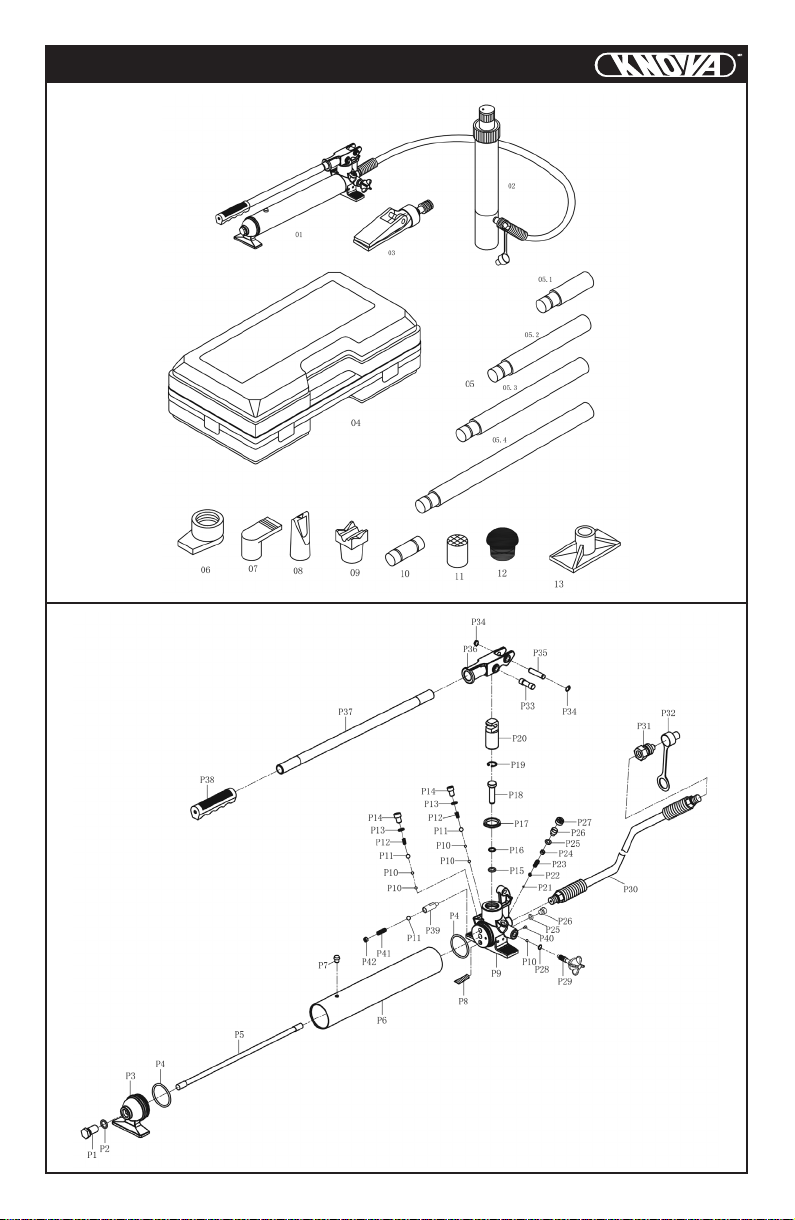
1.1 La capacidad máxima del émbolo es
de 10 ton. NO exceda esta
capacidad nominal.
1.2 Cuando se utilizan tubos de
extensión, la capacidad nominal
siempre se reduce en un 50% por
cada tubo conectado.
1.3 La capacidad máxima del esparcidor
es de 0.5 ton. Y la capacidad máxima
del dedo del pie del ariete y del
émbolo o 0.8 toneladas. NO exceda
estas capacidades nominales cuando
use estos accesorios.
1.4 No use este equipo como un
dispositivo elevador de vehículos o
como un soporte para vehículos.
1.5 Mantenga a los niños y otras
personas no autorizadas lejos del
área de trabajo.
1.6 Retire la ropa suelta. Quite los lazos,
relojes, anillos y otras joyas, y
contenga el pelo largo.
1.7 Siempre use gafas de seguridad
aprobadas por ANSI cuando opere el
kit de reparación.
1.8 Mantenga el equilibrio y el equilibrio
adecuados. No se exceda ni use
calzado antideslizante.
1.9 Solo use este equipo en una
supercie que sea estable. Nivel, seco
y no resbaladizo, y capaz de sostener
la carga. Mantenga la supercie
limpia, ordenada y sin materiales no
relacionados y asegúrese de que
haya una iluminación adecuada.
1.10 NO permita que el vástago del pistón
(R03) se extienda hasta superar la
carrera máxima del émbolo.
1.11 Cuando las válvulas del acoplador
estén desconectadas, siempre use
una tapa contra el polvo para
mantener limpio el sistema hidráulico.
1.12 NO arroje objetos pesados sobre
la manguera y NO tuerza la
manguera. Siempre mantenga la
manguera limpia para evitar daños a
la manguera y los acopladores.
1.13 Mantenga el equipo alejado del
calor o del fuego, ya que puede
dañarlo o debilitarlo.
1.14 NO opere este equipo cuando esté
cansado y bajo la inuencia del
alcohol, drogas o cualquier
medicamento intoxicante.
1.15 NO permita que personas no
capacitadas operen el equipo y NO
le haga ninguna modicación.
1.16 NO exponga el equipo a la lluvia ni a
ningún otro tipo de mal tiempo.
1.17 Use una persona calicada para
mantener el equipo en buenas
condiciones. Manténgalo limpio para
el mejor y más seguro rendimiento.
1.18 Si el equipo necesita reparación
y / o hay piezas que necesitan ser
reemplazadas, haga que sean
reparadas por técnicos autorizados
y solo use las piezas de repuesto
suministradas por el fabricante.
1.19 ADVERTENCIA: Las advertencias,
precauciones e instrucciones
discutidas en el manual de
instrucciones no pueden cubrir todas
las condiciones posibles y la situación
puede ocurrir. El operador debe
comprender que el sentido común y
la precaución son factores que no
pueden incorporarse en este
producto, sino que deben ser
suministrados por el operador.
2. ESPECIFICACIONES
Capacidad calicada: 10 Ton.
Presión de salida de la bomba:
63 MPa (9,137 psi)
Altura mínima cilindro: 322 mm.
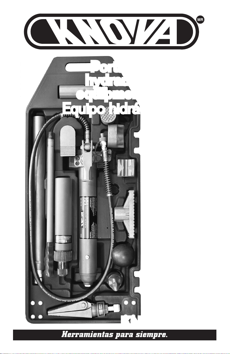
Equipo hidráulico portátil 10 Ton.
KN 7402-10PA
Altura máxima cilindro: 452 mm.
Carrera del pistón: 130 mm.
Llenado de aceite: 800 ml.
Peso neto: 31 Kg.
Peso bruto: 32.2 Kg.
Por favor, lea atentamente estas instrucciones, tenga en cuenta las advertencias de las
indicaciones de seguridad, utilice el producto correctamente y con cuidado para el n
para el que está destinado, el no hacerlo puede causar daños a la propiedad y/o lesiones
personales graves, por favor, mantenga este manual de instrucciones de seguridad para
uso futuro.

3.1 Conecte el pistón hidráulico, la
manguera y la unidad de bomba al
mismo tiempo, asegúrese de haber
asegurado rmemente los acopladores
antes de bombear.
Advertencia: inspeccionar antes de
cada uso. No lo use si observa
componentes doblados, rotos, con
fugas, dañados o cualquier parte
sospechosa y / o ha sido sometido a
una carga de choque.
3.2 Cierre rmemente la válvula de
liberación (P29) girándola en el
sentido de las agujas del reloj.
3.3 Ajuste el pistón lentamente para
hacer que la carga sea coaxial con
el ariete.
4.1 Cuando no esté en uso, guarde el
equipo en un lugar seco con el pistón
de la bomba (P20) y el ariete
totalmente retraído.
4.2 Revise periódicamente el pistón y el
pistón de la bomba para detectar
signos de oxidación o corrosión.
Limpie las áreas expuestas con un
paño limpio y engrasado.
Advertencia: ¡Nunca use papel de lija
o material abrasivo en estas
supercies!
4.3 Una capa de aceite lubricante liviano
en los puntos de pivote, los ejes y las
bisagras ayudará a prevenir la
oxidación y asegurará que los
conjuntos de la bomba se muevan
libremente. Periódicamente
lubrique los puntos de pivote, los ejes
y las bisagras con un aceite lubricante
liviano, según sea necesario.
3. INSTRUCCIONES DE OPERACIÓN
NOTA: La bomba se puede usar en
cualquier posición desde horizontal
a vertical. Mantenga siempre el
extremo de la manguera de la bomba
hacia abajo cuando no esté en
posición horizontal.
3.5 Bombee el mango (p37) hacia arriba
y hacia abajo para suministrar presión.
3.6 Cuando termine el trabajo, GIRE
LENTAMENTE y CUIDADOSAMENTE
la válvula de liberación en sentido
contrario a las manecillas del reloj
(nunca más de una vuelta) para liberar
la presión hasta que el pistón se
retraiga a la posición deseada.
4. MANTENIMIENTO
4.4 Con el pistón completamente bajo,
coloque la unidad de bombeo en su
posición normal y nivelada. Retire
el tapón (P07) para vericar el nivel
de aceite hidráulico. Si no es
adecuado, agregue aceite hidráulico
de alta calidad según sea necesario.
Advertencia: NO use líquido de frenos
ni ningún otro uido inapropiado y
evite mezclar diferentes tipos de aceite
cuando agregue aceite hidráulico.
4.5 Para garantizar el mejor rendimiento y
una mayor vida útil del equipo, reemplace
el aceite hidráulico completo al menos una
vez al año. Con el ariete completamente
bajado, retire el tapón (P07).
4.6 Nota: elimine el aceite hidráulico de
acuerdo con las reglamentaciones locales.
4.7 Se recomienda que una inspección anual
sea realizada por técnicos calicados.
SÍNTOMA CAUSAS POSIBLES ACCIÓN CORRECTIVA
Depósito sobrellenado
Vínculos de unión
Nivel de aceite bajo
5. RESOLUCIÓN DE PROBLEMAS
La válvula de liberación no está bien cerrada
Condición de sobrecarga Cierre bien la válvula
de liberación
El cilindro
no mantiene
la carga
El cilindro no
baja después
de la descarga
El cilindro no se
extiende a la
carrera completa
Bajo
rendimiento
El cilindro
no levanta
la carga
La válvula de liberación no está bien cerrada
Mal funcionamiento de la unidad hidráulica
Cierre bien la válvula de liberación
Reemplace el cilindro y/o la bomba
Drene el aceite hasta
el nivel adecuado
Limpie y lubrique las partes móviles
Nivel de aceite bajo Añada aceite hidráulico
Añada aceite hidráulico

6. LISTA DE PARTES
EQUIPO
1 Bomba
(incl. mangera)
1
2 Cilindro 1
3 Separador 1
4 Estuche de plástico 1
5 Extensiones 1
6 Punta de cilindro 1
7 Punta de ariete 1
8 Cabeza de cuña 1
9 Bse en V 1
10 Conector macho 1
11 Asiento serrado 1
12 Cabeza de goma 1
13 Base plana 1
BOMBA
P1 Tornillo 1
P2 Anillo-O 1
P3 Pie de bomba 1
P4 Anillo-O 2
P5 Tirante 1
P6 Depósito 1
P7 Tapon 1
P8 Filtro de aceite 1
P9 Bloque de válvula 1
P10 Balín de acero 5
P11 Balín de acero 3
P12 Resorte 2
P13 Cojinete 2
P14 Tornillo 2
P15 Anillo-O 1
P16 Anillo de sello 1
P17 Anillo-U 1
P18
Pequeño nucleo de bomba
1
P19 Arandela 1
P20
Gran nuecleo de bomba
1
P21 Balín de acero 1
P22 Casquillo de balín 1
P23 Resorte 1
P24 Tornillo 1
P25 Anillo-O 2
P26 Tapón 2
P27 Tornillo protector 1
P28 Anillo-O 1
P29 Válvula de liberación 1
P30 Manguera 1
P31 Conector 1
Parte No. CantidadDescripción Parte No. CantidadDescripción
P32
Cubierta de polvo de manguera
1
P33 Perno 1
P34 Arandela 2
P35 Perno 1
P36
Conector del maneral
1
P37 Maneral 1
P38
Cubierta del manertal
1
P39 Asiento de ajuste 1
P40 Casquillo de balín 1
P41 Resorte 1
P42 Tornillo 1
PISTON
RO1 Tapa 1
R02 Arandela 1
R03 Vastago del émbolo 1
R04 Arandela 1
R05 Cojinete 1
R06 Sello de anillo 1
R07 Anillo-U 1
R08 Arandela 1
R09 Tuerca 1
R10 Resorte 1
R11 Tornillo 1
R12 Tapa de protección 1
R13 Anillo para pistón 1
R14 Cilindro 1
R15 Perno 1
R16 Tuerca 1
R17 Acoplador 1
R18 Anillo-O 1
R19 Tapa 1
SEPARADOR
S1 Perno 1
S2 Arandela 2
S3 Mordaza móvil 1
S4 Resorte 1
S5 Mordaza ja 1
S6 Pistón 1
S7 Sello de copa 1
S8 Anillo-O 1
S9 Tapa de cierre 1
S10 Tuerca 1
S11 Acoplador 1
S12 Anillo-O 1
S13 Cubierta 1

7. DIAGRAMAS
Equipo
Bomba

7. DIAGRAMAS
Pistón
Separador

www.knova.com.mx
Table of contents
Languages:
Other KNOVA Power Tools manuals

KNOVA
KNOVA KN 5025 User manual

KNOVA
KNOVA KN HG-1500 User manual

KNOVA
KNOVA KN 7428 User manual

KNOVA
KNOVA KN 5012 User manual

KNOVA
KNOVA KN RO-1313 User manual

KNOVA
KNOVA KN 7420-20A User manual

KNOVA
KNOVA KN DP-3000N User manual

KNOVA
KNOVA KN DP-2000N User manual

KNOVA
KNOVA KN 7420-12 User manual

KNOVA
KNOVA KN DP-2500N User manual
Popular Power Tools manuals by other brands

Fein
Fein MULTIMASTER FMM 250 instruction manual

JB GURY
JB GURY UNIVERSAL Comet CENTURY Parts and service manual

Dynapac
Dynapac LH 300 operation & maintenance

Josef Kihlberg
Josef Kihlberg JK20T779 operating instructions

F.F. Group
F.F. Group CJS 20V/80 PLUS Original instructions

Ferm
Ferm FCT-300 user manual