KNS SUPERTRACK S4 User manual

INSTALLATION AND OPERATION MANUAL
FOR SUPERTRACK MODEL S4
Ku-BAND TV-RO ANTENNAS
KNS Inc.
Tel)+82-42-932-0351~2
Fax)+82-42-932-0353
Web) http://kns-kr.com/
28.03. 2011

i
KNS SuperTrack systems are manufactured in the
Republic of South Korea.
Copyright Notice
All Rights Reserved. The information contained in this document is proprietary to KNS,
Inc. This document may not be reproduced or distributed in any form without the
consent of KNS, Inc. The information in this document is subject to change without
notice.
Copyright 2010 KNS, Inc.

ii
Revision History
Revision Date Description By Remarks
1.0 02.22. 2010 Initial Release
(PCU Ver. 1.95 & ACU Ver. S1.12)
Hong
1.1 05.17. 2010 Update text and figures about
changed ACU software
(PCU Ver. 1.96 & ACU Ver. E1.20)
Hong
1.2 10.07. 2010 Update text and figure about PCU
changes from DVB S1 to DVB S2
(PCU Ver. 2.13 & ACU Ver. E1.20)
Hong
1.3 Mar 28. 2011 Add the SCS version
(PCU Ver. 2.21 & ACU Ver. E1.23)
Hong

a
Contents
1.
Introduction.................................................................................. 1
1.1.
Purpose................................................................................................1
2.
Installation.................................................................................... 2
2.1.
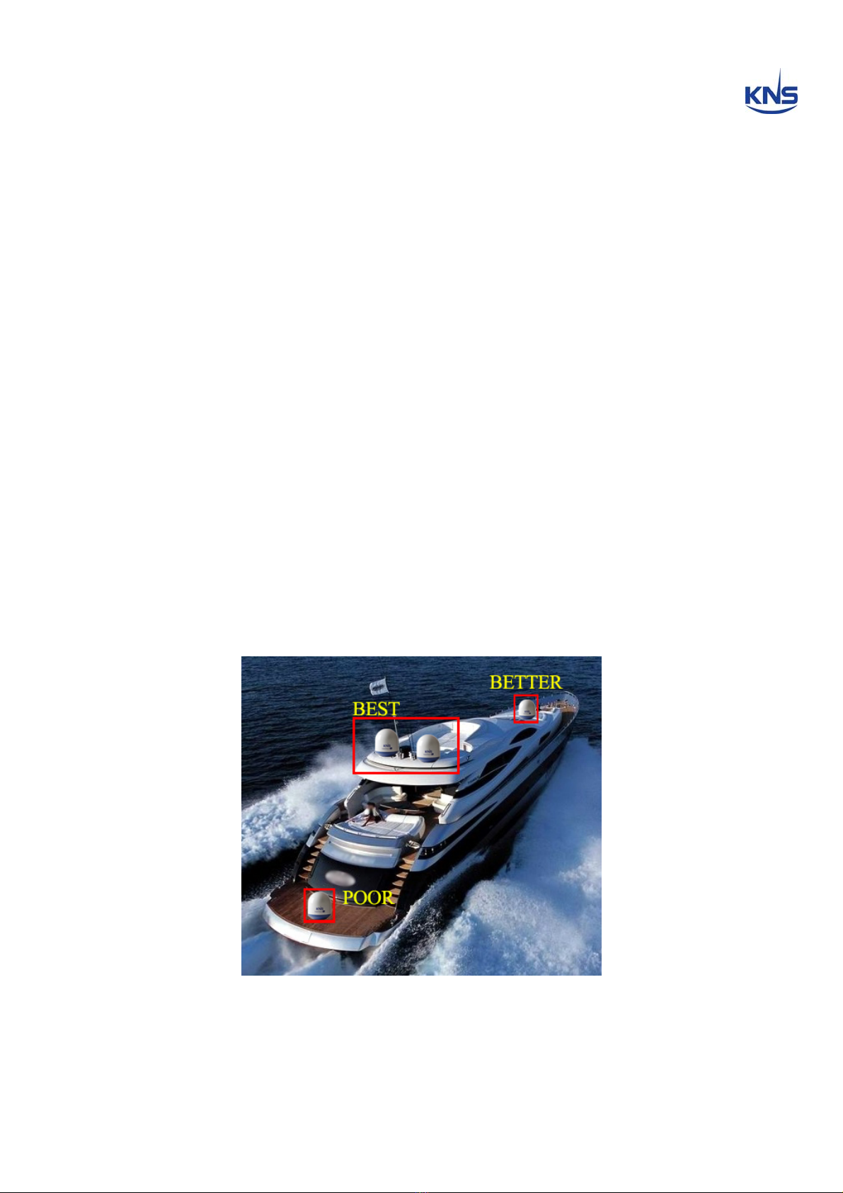
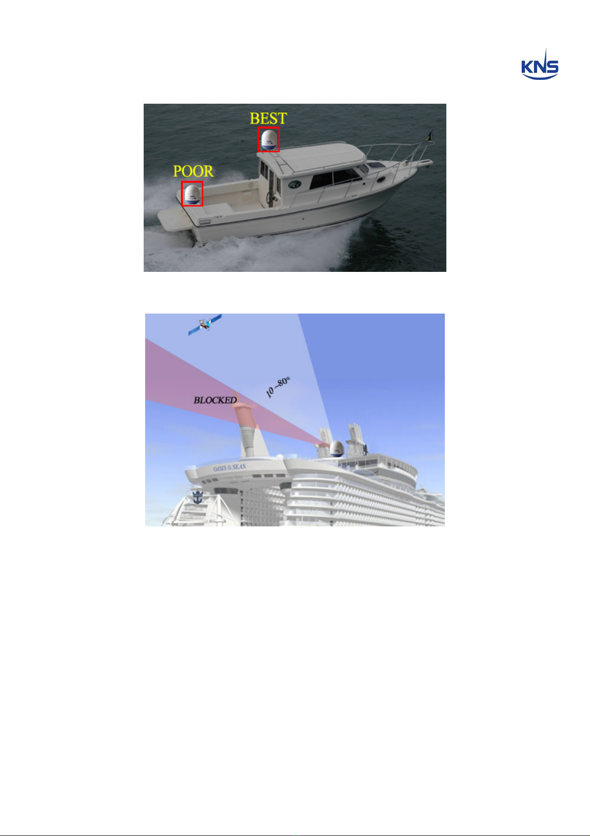
Site Selection.......................................................................................2
2.2.
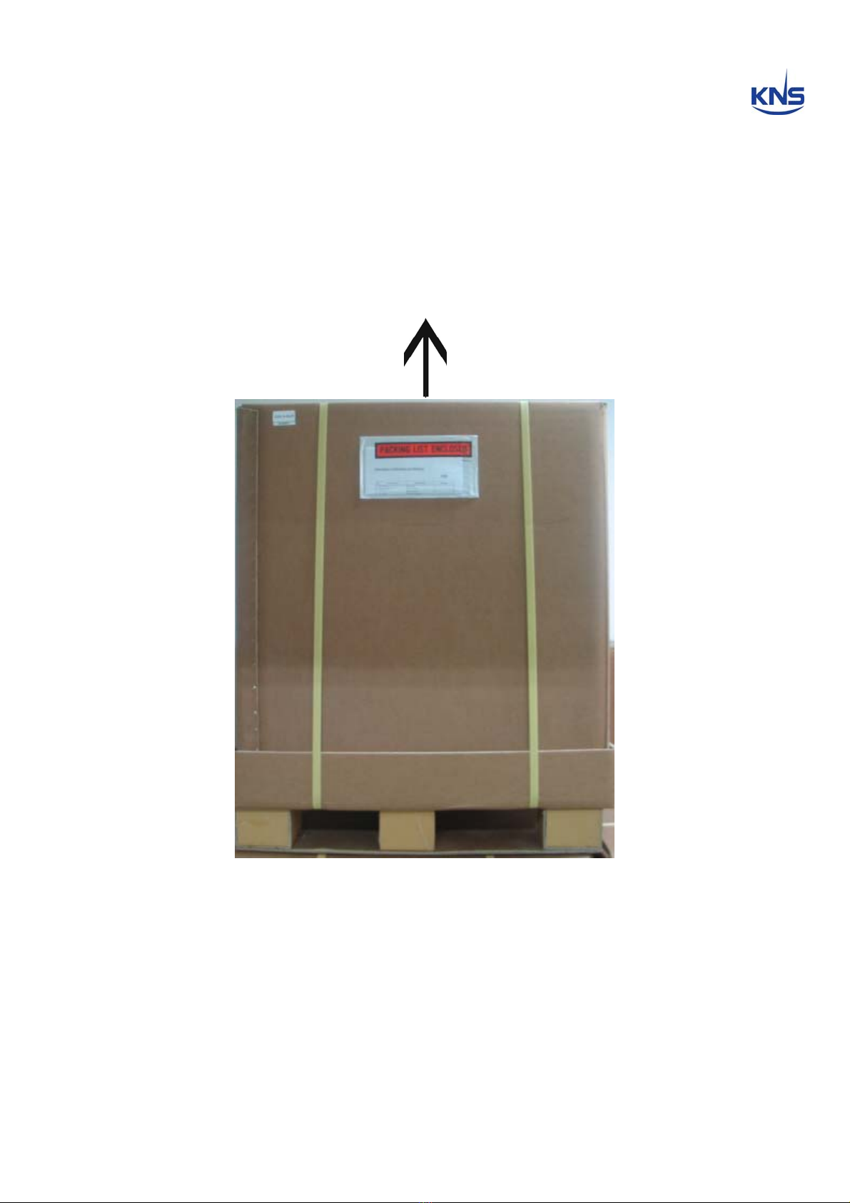
Unpacking the Unit..............................................................................4
2.3.
Equipment and Cable Installation......................................................5
2.4.
Antenna Unit Mounting.......................................................................6
2.5.
ACU Mounting....................................................................................10
2.6.
Gyro Connection(Optional) ..............................................................11
2.7.
Cable Connection..............................................................................14
3.
Operation.................................................................................... 22
3.1.
Front Panel Functions.......................................................................22
3.2.
ACU Display Operation.....................................................................25
3.3.
Set-up Mode.......................................................................................27
4.
How to Operate SCS.................................................................. 38
4.1.
Connect to PC....................................................................................39
4.2.
Selection Area and Satellite .............................................................42
4.3.
Skew Setting......................................................................................48
4.4.
Antenna State ....................................................................................50
4.5.
Selection Area and Satellite .............................................................53
Appendix A: Example of Setting the Satellite’s Parameters
Using SCS ........................................................................................ 64
Appendix B: Error Code Definition.............................................. 69
Appendix C: Specifications .......................................................... 72
Appendix D: Satellite Information................................................ 73
Appendix E: Radome and Antenna Mounting Holes Layout .... 77

1
1. Introduction
1.1.Purpose
The purpose of this manual is to provide the necessary information required by the
end user, customer and installer to successfully install the S4 antenna and controller
and to program the KA-70 for operation.
It is recommended that all personnel responsible for operating S4 systems should
know which type of system they have, read and understand the basic terms, and be
familiar with the operation of these systems.
Although installations may be completed by the customer’s preferred personnel, it is
also recommended that personnel be trained in the KNS suite of equipment installation
procedures and trained by the relevant KNS Inc. experts.

2
2. Installation
2.1.Site Selection
Determine the optimum mounting location for the antenna radome assembly. It should
be installed where:
1. The antenna has a clear line-of-sight view of as much of the sky as is practical.
Choose a location where masts or other structures do not block the satellite signal from
the dish as the boat turns.
2. The antenna is situated at least 5m away from other transmitting antennae (HF,
VHF and radar) that may generate signals that may interfere with the SuperTrack S
series antenna. The further away the SuperTrack S series antenna is from other such
antennae, the less impact their operation will have on it.
The antenna radome assembly should be rigidly mounted on the boat. If necessary,
reinforce the mounting area to ensure that it does not flex due to the boat’s motion or
vibration.
Figure 2-1 Best Location I

3
Figure 2-2 Best Location II
Figure 2-3 Antenna Blockages

4
2.2. Unpacking the Unit
Cut the band and remove the items of antenna equipment. Do not turn the box on its
side to tip or roll out the product, or turn the box upside down to remove it.
Lift carton box straight up
Figure 2-4 Unpack the Antenna

5
2.3.Equipment and Cable Installation
The coax connector bracket beneath the radome is labeled. The functional assignment
of these labels is as follows:
S4 Connectors
RF1: Connect to the multi-switch (Vertical Low).
RF2: Connect to the multi-switch (Horizontal Low).
RF3: Connect to the multi-switch (Vertical High).
RF4: Connect to the multi-switch (Horizontal High).
ACU: Connect to the ACU.
NOTE
: The RF4 coax connection must be plugged into the 18VDC port of your multi-
switch. This must be the horizontal high band input of your four-ports Multi-switch when
using a Quattro LNB.
NOTE
: Unused coax connections (on the connector bracket) MUST be terminated with
a 75ohm terminator.
NOTE
: We recommend the following cable types for cable lengths:
-within 20m: RG6
-within 50m: RG11
-within 100m: LMR400
-within 200m: LMR600
NOTE
: Impedance of cable is 75ohm. Also you can select the other cable types.
However we recommend all attenuation of cable is under 20dB at 2.5GHz.
Figure 2-5 RF Connector Bracket

6
2.4.Antenna Unit Mounting
Drill four bolt holes and cut out a cable access hole on the mounting site. (See
reference appendix.)
Position the foam seal on the mounting surface with the hole centered over the cable
access cut-out.
Position the base plate over the mounting holes and the cable access hole, and then
align the radome base plate’s “Bow” label (shown in Figure 2-6) with the ship’s bow.
Figure 2-6 “BOW” Label of the Radome Base
1. Connect the data/power and the RF cables from below decks to the base plate
with a 7/16” wrench, applying 30 pounds of torque. Check the label on both ends
of each RF cable to match its antenna base-plate connector. Do NOT use Teflon
gel on the cable fittings as it reduces signal strength at high frequencies.
2. Install flat washers and spring washers and a mounting bolt to each mounting hole of
the radome base from the underside of the mounting surface. Apply Loctite 241 to the
threads of the mounting bolt up near the mounting surface and tighten each of the 4
bolts to 24 in-lb (21 kg-cm) of torque [finger tight, then about 1/4 turn tighter] with a
wrench. DO NOT OVER-TIGHTEN. You have to install mounting bolts of the proper
length. If a bolt is too long, the extra length of threaded rod that extends above the
radome base should be cut off.

7
Figure 2-7 Tighten the nuts from below

8
3.
Remove the jigs and wire ties holding the Antenna.
Please refer to Figures 2-8
and 2-9, 2-10 below.
Figure 2-8 Fixed Screw for Elevation
Figure 2-9 Fixed Screws for Cross

9
Fixed Screws
for Azimuth
Figure 2-10 Fixed Screws for Azimuth

10
2.5.ACU Mounting
The ACU may be mounted either horizontally or vertically.
1. The ACU should be placed in a dry location that is convenient for the user.
2. It must be situated in a place that is not susceptible to magnetic interference; nor
must it be situated on a level surface.
3. It should be placed so that the LCD display is visible and the buttons are easily
accessible.
Figure 2-11 KA-70 ACU

11
2.6.Gyro Connection(Optional)
The SuperTrack S4 receives NMEA-type gyro signals when the compass mode is
‘Gyro’. Connect the NMEA port of the ACU back panel with a ship’s gyro using a 9-pin
connector (female type).
Figure 2-12 NMEA connector
Figure 2-13 Female-type 9-pin connector

12
Gyro Cable Connection
The cable connection differs according to the type of NMEA. Connect the NMEA port
with the ship’s gyro, as indicated in Figures 2-14 and 2-15 below.
Pin No. Pin Name
1 RX-
2 RX+
3 TXD
4 DC 24V
5 GND
6 Dummy
7 GND
8 Dummy
9 Dummy
Table 2-1 Using the pin number of the ACU Connector for the NMEA type
Figure 2-14 Cable Connection NMEA 422/485
Figure 2-15 Cable Connection NMEA 232

13
NOTE
: KA-70 ACU can receive the various format of NMEA, as follow: HDT; HDG;
HDM. KA-70 ACU(ver. E.1.23) can accept the gyro signal even though there is no
checksum as below.
$HEHDT,x.x,T*hh<CR><LF>
$HEHDG,x.x,x.x,a,x.x,a*hh<CR><LF>
*hh means checksum of format.

14
2.7.Cable Connection
For the SuperTrack S4 to work, you must connect the RF cables to your satellite TV
receiver(s). Each RF cable must be an RF (75 ohms) cable fitted with F-type
connectors. The RF cables should already be connected to the antenna base plate.
There should be two ~ five coax cables routed from the ACU to the Antenna unit
according to your configurations. Note that Data and Power are transmitted through a
single coax cable.
This cable should be connected to the ACU labeled “RF
connector of the antenna base plate” and the connector of the ACU labeled
“ANTENNA.”
The remaining coax cable routing depends on your configuration. Due
to the signal polarization of the satellites, it is possible for the SuperTrack S4 to
support more than two satellite TV receivers aboard a boat. To install more than two
satellite TV receivers/TV pairs, an active multi-switch is placed between the Antenna
Unit and the Satellite TV receivers. The following sections provide details for the
installation of both a single satellite TV receiver and multiple satellite TV receivers.
To connect the SuperTrack S4 to your satellite TV receiver(s), choose one of the
following configurations (based on the number of satellite TV receivers you will
connect to the antenna):
Option 1 - Connecting one satellite TV receiver for one satellite
Option 2 - Connecting one satellite TV receiver for satellite pairs with auto
switching
Option 3 - Connecting satellite TV receivers with European LNB
Option 4 - Connecting multi satellite TV receivers with auto switching
Connecting one satellite TV receiver for one satellite (Only use the ‘HH’
polarity of the satellite)
One satellite TV receiver for one satellite is the simplest type of cable installation. Only
two coaxial cables should be connected between the antenna unit and the satellite TV
receiver, as shown in Figure 2-16. One end of the RF cable should already be
connected to the connector labeled “RF4” on the base of the SuperTrack S4 antenna.
Connect the other end of the RF4 cable to the satellite TV receiver connector labeled
“LNB,” “ANT/SAT,” or “satellite IN.” And, the “ACU” connector of the antenna base plate
must also be connected to the “ANTENNA” connector of the ACU. In this configuration,
every satellite should be selected manually using the ACU.

15
NOTE
: Before you connect an RF cable to a satellite TV receiver, turn on the satellite
TV receiver and TV and verify that there is no AC voltage on the satellite TV receiver’s
input connector, as measured between the center conductor and the shield. If AC
voltage is present on the connector, DO NOT connect the RF cable until you have
corrected the problem. This is a potentially dangerous condition that will damage the
antenna’s electronics.
Figure 2-16 One Satellite TV Receiver Installation
Connecting one satellite TV receiver for satellite pairs with auto switching
(Only use the ‘HH’ polarity of the satellite)
If you want to use two satellites with one satellite TV receiver, you can use automatic
satellite switching using the DiSEqC. This versatility gives you the capability of
receiving audio and video programming from two satellites. One satellite TV receiver
for two satellites is also a simple mode of cable installation. Two coaxial cables should
be connected between the antenna unit and the ACU, as shown in Figure 2-17. And,

16
one coaxial cable and a passive splitter should be connected between the ACU and the
satellite TV receiver. The RF4 connector of the SuperTrack S4 must be connected to
the “SAT IN” connector of the satellite receiver. And, the “ACU” connector of the
Antenna unit must also be connected to the “ANTENNA” connector of the ACU. In this
configuration two satellites can be selected automatically according to the satellite TV
receiver signal. (Refer to the ‘PROGRAM SATELLITE’ section.)
Figure 2-17 One Satellite TV Receiver with Auto Switching
Table of contents