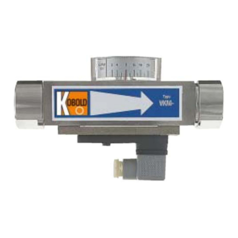
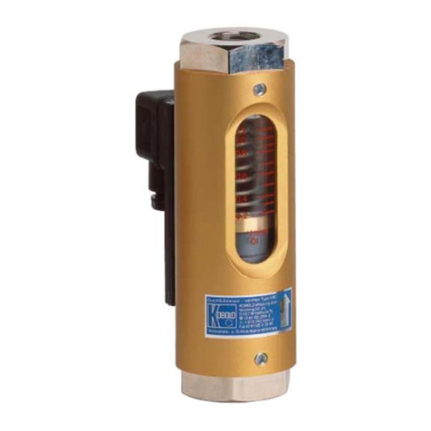
Kobold VKM User manual

Operating Instructions
for
Viscosity Compensated
Flow Meter / Monitor
Model: VKM

VKM
page 2 VKM K20/0522
1. Contents
1.Contents ........................................................................................................ 2
2.Note .............................................................................................................. 3
3.Instrument Inspection .................................................................................... 3
4.Regulation Use ............................................................................................. 4
5.Operating Principle ........................................................................................ 5
6.Mechanical Connection ................................................................................. 6
7.Electrical Connection .................................................................................... 6
7.1.Switching Output VKM-1.. and VKM-3.. ............................................... 6
7.2.Example for Contact Protective Measures ........................................... 7
7.3.ADI-Evaluation Electronics VKM-7.. .................................................... 8
7.4.Compact electronic VKM-8... ............................................................... 8
8.Use in hazardous area .................................................................................. 9
8.1.ATEX contact ...F0... (only VKM-1… and VKM-3…) .......................... 11
8.2.ATEX reed contact 41R57** ............................................................. 11
9.Commissioning............................................................................................ 18
9.1.General .............................................................................................. 18
9.2.Switching Output VKM-1.. and VKM-3.. ............................................. 18
9.3.ADI-Electronic Analyser VKM-7.. ....................................................... 19
9.4.Compact electronic VKM-8... ............................................................. 19
10.Maintenance ............................................................................................... 19
11.Technical Information .................................................................................. 20
12.Order Codes ............................................................................................... 22
13.Recommended Spare-Parts ........................................................................ 25
14.Dimensions ................................................................................................. 26
15.EU Declaration of Conformance (VKM) ...................................................... 28
16.UK Declaration of Conformity (VKM) ........................................................... 29
17.EU declaration of conformance (reed contact 41R57**) .............................. 30
18.Statement of conformity reed contact 41R57** ........................................... 31
19.Declaration of the Manufacturer (F0) .......................................................... 35
20.EC-Type Examination Certificate Magnetic reed switch (F0) ...................... 36
21.IECEx certificate (F0) .................................................................................. 39
Manufactured and sold by:
Kobold Messring GmbH
Nordring 22-24
D-65719 Hofheim
Tel.: +49(0)6192-2990
Fax: +49(0)6192-23398
E-Mail: [email protected]
Internet: www.kobold.com
VKM
VKM K20/0522 page 3
2. Note
Please read these operating instructions before unpacking and putting the unit into
operation. Follow the instructions precisely as described herein.
The instruction manuals on our website www.kobold.com are always for currently
manufactured version of our products. Due to technical changes, the instruction
manuals available online may not always correspond to the product version you
have purchased. If you need an instruction manual that corresponds to the
purchased product version, you can request it from us free of charge by email
([email protected]) in PDF format, specifying the relevant invoice number and
serial number. If you wish, the operating instructions can also be sent to you by
post in paper form against an applicable postage fee.
The devices are only to be used, maintained and serviced by persons familiar with
these operating instructions and in accordance with local regulations applying to
Health & Safety and prevention of accidents.
When used in machines, the measuring unit should be used only when the
machines fulfil the EC-machine guidelines.
as per PED 2014/68/EU
In acc. with Article 4 Paragraph (3), "Sound Engineering Practice", of the
PED 2014/68/EU no CE mark.
Diagram 8, Pipe, Group 1 dangerous fluids
3. Instrument Inspection
Instruments are inspected before shipping and sent out in perfect condition.
Should damage to a device be visible, we recommend a thorough inspection of the
delivery packaging. In case of damage, please inform your parcel service /
forwarding agent immediately, since they are responsible for damages during
transit.
Scope of delivery:
The standard delivery includes:
Viscosity Compensated Flow Meter / Monitor model: VKM

VKM
page 4 VKM K20/0522
4. Regulation Use
Any use of the device, which exceeds the manufacturer’s specification, may
invalidate its warranty. Therefore, any resulting damage is not the responsibility of
the manufacturer. The user assumes all risk for such usage.
The models VKM are used for measuring and monitoring of viscous liquid flows
(max. 540 mm2/s). They are suitable for measuring clean and homogeneous fluids
which are compatible with on the instrument materials used.
If using higher viscosity media, large deviations will occur to the measured values.
Large dirt particles may impede the movement of the float and cause false alarm
conditions.
Ferritic particles deposited on the float (with magnet) may lead to the same effects.
The instruments are provided as follows:
Flow measurement (only for Model VKM-2.. and VKM-3..)
The actual flow rate may be read off the magnetically operated pointer indicator
mounted on the instrument. The scale indicates the flow rate directly in litres per
minute.
Limit Value Switches (only for Model VKM-1.. and VKM-3..)
The instrument is fitted with one or two adjustable limit value switches for the
monitoring of flow throughput values.
Type of contacts:
N/O contact (standard)
Changeover contact (standard)
N/O (cCSAus)
Changeover (cCSAus)

VKM
VKM K20/0522 page 5
5. Operating Principle
A hollow float with a sharp-edged orifice is located within a
cylindrical bored metal housing. The flowing medium raises
the float against the spring force. The position of the float
corresponds to a particular flow rate which may be read
from the needle indicator mounted on the instrument.
Permanent magnets are fitted around the float which
operates reed contact switches external to the flowing
medium chamber.
The operation of the contacts is voltage free and works by
means of magnetic force. i.e.: the contact is hermetically
sealed from the flowing medium.

VKM
page 6 VKM K20/0522
6. Mechanical Connection
Before installation:
It should be confirmed that the maximum allowed
operating pressures and operating temperatures of the
equipment are not exceeded.
(see table: standard material combinations).
The instruments may be mounted in any flow
direction. No recalibration is required when changing
position. The flow must always take place in the
direction of the arrow (see label).
Remove all transport packing and ascertain that no
packing material is left in the instrument.
Sealing of the connection threads should be carried
out with Teflon tape or similar.
The instruments must not be installed within an
induction field.
if possible, after the mechanical installation, it should
be checked that the connection thread to pipe is fully
sealed (see section 9).
7. Electrical Connection
7.1. Switching Output VKM-1.. and VKM-3..
Make sure that the supply wires are de-energized.
Loosen the holding screw of the plug and pull out the cap
from the socket.
Make connection inside the plug-cap according to the wiring
diagram.
If the contact switch point has not been adjusted yet, it would
be appropriate to do so at this point.
(see section 9 Commissioning).
Push the plug onto the socket, secure by using the locking
screw. (see section 9 Commissioning).

VKM
VKM K20/0522 page 7
Attention! The given electrical specifications of reed switches must
never be exceeded, even for a short time. For higher switching
capacities we recommend the use of contact protection relays (e.g. or
model MSR) or any other contact protection device.
After your designated external units are connected to the limit contact and
adjustment of desired switching points is accomplished, then all the work regarding
connections is completed.
The unit can now be set in operation.
7.2. Example for Contact Protective Measures
For capacitive and inductive loads (long cables and relay/protection) we
recommend the following protective schemes.

VKM
page 8 VKM K20/0522
7.3. ADI-Evaluation Electronics VKM-7..
For connection of the power supply and the output signals please check with the
operating instructions of the corresponding ADI electronic.
Information! The measuring input of the ADI is already factory-
set.
7.4. Compact electronic VKM-8...
Compact electronic: (..C30R, ..C30M)
Compact electronic: (..C34P, .. C34N)

VKM
VKM K20/0522 page 9
8. Use in hazardous area

VKM
page 10 VKM K20/0522

VKM
VKM K20/0522 page 11
8.1. ATEX contact ...F0... (only VKM-1… and VKM-3…)
II 2G Ex mb IIC T6 Gb
II 2 D Ex mb IIC T80 °C Db
max. 250 V
AC
/1.5 A/100 VA
8.2. ATEX reed contact 41R57**
ATEX N/O contact 41R57
II 3G Ex ic IIC T4 Gc
II 3 D Ex ic IIIC T125 °C Dc
-20 °C ≤Ta≤80 °C
max. 250 V
AC/DC
/1.5 A/100 W/100 VA
ATEX changeover contact 41R57U
II 3G Ex ic IIC T4 Gc
II 3 D Ex ic IIIC T125 °C Dc
-20 °C ≤Ta≤80 °C
max. 250 V
AC/DC
/1 A/30 W/60 VA

VKM
page 12 VKM K20/0522
Ex-relevant excerpt of the operating instructions of the reed contact
41R57 **
1. Preambel
This excerpt of the operating instructions only represents the ex-relevant aspects.
It is copied into the original operating manual in the same or analogous form;
Textual changes are permitted, the ex-relevant statements remain.
To ensure the function and for your own safety, please read the enclosed operating
instructions carefully before you begin the installation. If you have any questions,
please contact the KOBOLD Messring GmbH, Hofheim. It applies with the original
operating instructions.
The following standard issues were considered in the evaluation of the product:
a) IEC 60079-0:2017 Ed. 7 / EN 60079-0:2018 Explosive atmospheres –
Part 0: Equipment - General requirements
b) IEC 60079-11:2011 Ed. 6 + Corr. 2012 / EN 60079-11:2012 Explosive
atmospheres - Part 11: Equipment protection by intrinsic safety "i"
2. General information on explosion protection
The reeds switches work together with various KOBOLD products and serve there
for monitoring. It is available as N/O contact or changeover contact.
The electrical connection is made via a plug - only in intrinsically safe systems.
The reed switch is intended for commercial use and may only be used in
accordance with the specifications in the technical documentation of Kobold and
the information on the nameplate. It is only operated together with certified products
via an intrinsically safe circuit. They comply with the valid standards and
regulations.
The installation regulations (e.g. EN 60079-14) for systems in potentially explosive
atmospheres must be observed.
Further important details can be found in the corresponding EC-type examination
certificate.
Permitted use
• The intrinsically safe reed switch can be used as follows:
• In Zone 2 (Gas-Ex, EPL Gc) in explosion groups IIA, IIB and IIC
• In Zone 22 (Dust-Ex, EPL Dc) in explosion groups IIIA, IIIB and IIIC
• The requirements for simple electrical equipment for use in intrinsically safe
circuits in zones 1/21 are fulfilled.
• The qualification regarding the surface temperature is T4. For all gases, vapors,
mists with an ignition temperature> 135 ° C the equipment is not an ignition
source.
• In the dust Ex area, 125 ° C is the reference temperature for further
consideration regarding the safety distance from the smoldering temperature.
• The ambient temperature range is -20 ° C ≤ Ta ≤ 80 ° C.

VKM
VKM K20/0522 page 13
2.1. Electrical characteristics for Ex i
Electrical data:
• Rated voltage up to 45 volt AC / DC
• Rated current up to 2 A
• UiIC ≤ 30 V AC / DC, IiIIC ≤ 250 mA
• UiIIB ≤ 45 V AC / DC, IiIB ≤ 2 A
• UiIIIC ≤ 45 V AC / DC, IiIIIC ≤ 250 mA
• Li = negligible, Ci = negligible
• Heating on the outer housing <15 K
2.2 Type code
The equipment is identified by the following type code:
Type Description Item-No. Remarks
41R57 A B
Type coding
41R57 Contact device
A
N/O contact
(
2 wires
)
, Plu
g
with black cap
Change-over contact (3 wires), Plug with grey
cap
B 70 – 75 with marking (not ex-relevant) 202.289 N/O
45
–
50 with markin
g
202.285 N/O
50
–
55 with markin
g
202.286 N/O
60 – 65 with marking 202.287 N/O
70
–
75 with markin
g
202.288 Chan
g
e-over
60
–
65 chan
g
e-over contact
202.290 Chan
g
e-over
2.3 Temperature class
The reed switch is suitable for temperature class T4 / T125 ° C.
2.4 General requirements
2.4.1 Intended Use
a) To ensure safe operation, the products may only be used according to the
instructions in the assembly instructions. During use, the legal and safety
regulations required for the respective application must be observed in
addition. This applies analogously when using accessories.
b) Failure to comply with the instructions given in this excerpt or in the case of
improper handling of the product will render our liability null and void. In
addition, the warranty on products and spare parts is void.
c) The products are not safety elements in terms of their intended use.
d) Only original parts of the manufacturer may be used.

VKM
page 14 VKM K20/0522
2.4.2 General safety instructions
The reed switch corresponds to the state of the art and is reliable. The reed switch
may pose a residual hazard if improperly used and operated by untrained
personnel.
Every person responsible for the installation, commissioning, maintenance or
repairing of the reed switch must have read and understood the assembly
instructions and in particular the safety instructions.
a) Follow the general rules of technology for the selection and proper
operation of a product.
b) All connected electrical and mechanical equipment must be suitable for
the respective application.
c) Observe the notes in these operating instructions as well as the
conditions of use and permissible data that appear from the imprints /
nameplates of the respective products.
d) It must be ensured that only product protection types corresponding to
the zones are installed!
e) The product is only approved for proper and intended use in a normal
industrial atmosphere. Immersion in liquids is not permitted.
f) It must be ensured that no falling objects can hit the product.
g) The operator must ensure the lightning protection for the entire system in
accordance with local regulations.
h) It is the responsibility of the installer to ensure that the function of the
reed switch in conjunction with the individual evaluation devices functions
properly and is approved for the intended use.
i) The intrinsically safe connection - including the reed switches - must be
made via approved / tested evaluation devices, which may need to be
equipped with suitable zener barriers or switching amplifiers.
3. Commissioning, installation
Depending on the IP degree of protection, the time for cleaning the equipment (dust
deposits) must be specified. Other important facts:
a) The product may be put into operation in Zone 2 (Cat. 3G, EPL Gc)
or in Zone 22 (Cat. 3D, EPL Dc in intrinsically safe circuits only by
specialists with a qualification similar to a qualified person according
to TRBS 1203.
b) The requirements for simple electrical equipment that apply to the
hazardous area of Zones 1/21 according to EN 60079-11 are fulfilled.
c) The products may only be used in the usual industrial atmosphere.
In the presence of aggressive substances in the air, the manufacturer
must always be consulted. The products must be adequately
protected in adverse environmental conditions.
d) Operation of the product is only permitted in fully assembled and
undamaged enclosures. In case of possible damage, a zone
carryover may have to be considered by the operator; Moreover,
operation of the housing is not permitted if the housing is damaged.
e) The environmental conditions specified in the operating instructions
must be adhered to and protected against adverse environmental
conditions.
f) Heat radiation from foreign products / components must also be
considered.

VKM
VKM K20/0522 page 15
g) The reed switch must be protected against inadmissible access of
liquids and / or soiling.
h) Fixed parts (e.g. due to frost or corrosion) must not be loosened by
force in the presence of an explosive atmosphere. Icing must
therefore be avoided.
i) The reed switch may only be subjected to minor vibrations, see also
IEC 34-14.
j) To ensure the discharge of electrostatic charges, the national
requirements must be considered.
k) In particular, isolated capacities must be prevented.
l) Only those zener barriers or switching amplifiers may be used whose
output circuits are approved / tested for use in potentially explosive
atmospheres. In Europe, use in Zones 1/21 requires an EC type-
examination certificate for the equipment concerned issued by a body
designated for explosion protection.
m) The voltage of the supply units must be less than or equal to the
voltage Ui of the reed switch.
n) The total current Io of the supply units must be less than or equal to
the current Ii of the reed switch.
o) For the installation of the intrinsically safe circuit, a control drawing
(system description) to be created by the installer / operator is
required.
p) Equipotential bonding must be established along the intrinsically safe
circuit when using a grounded supply.
q) The certificates must be taken into account, including the special
conditions specified therein.
r) Resistant parts of the product (e.g. due to frost or corrosion) must not
be forcibly loosened in the presence of an explosive atmosphere.
s) Within the potentially explosive area, installation may only be carried
out taking into account the locally applicable installation regulations.
The following conditions must be observed (incomplete):
t) Installation and maintenance may only be carried out in an explosion-
free atmosphere and in compliance with the regulations in force in
the country of the operator.
u) Additional precautions must be taken if the presence of hydrogen
sulphide, ethylene oxide and / or carbon monoxide is to be expected:
these substances have very low ignition energy!
v) In the presence of these substances and in the presence of a
substance of the explosion group IIC and in the case of presumably
existing potentially explosive atmosphere, only spark-free tools may
be used!

VKM
page 16 VKM K20/0522
4. Maintenance, servicing
Definition of terms according to IEC 60079-17:
Maintenance and Repair: A combination of all activities performed to maintain or
recover an item in a condition that meets the requirements of the specification in
question and ensures the performance of the required functions.
Inspection: An activity involving the careful examination of an object, with the aim
of obtaining a reliable statement of the condition of the object, carried out without
disassembly or, if necessary, with partial disassembly, supplemented by measures
such as measurements becomes.
Visual inspection: A visual inspection is a test that detects visible faults, such as
missing screws, without the use of access devices or tools.
Close-up Test: A test that identifies, in addition to the aspects of visual inspection,
such errors, such as loose screws, which can only be obtained by using access
devices, such as a screwdriver, e.g. steps (if necessary), and tools are visible. For
close-up tests, housing usually does not need to be opened or the equipment must
be de-energized.
Detail test: A test that detects, in addition to the aspects of close-up testing, such
defects as, for example, loose connections that can only be recognized by opening
housings and / or, if necessary, using tools and test equipment.
a) Maintenance measures may only be carried out by qualified persons.
b) Only use accessories in potentially explosive atmospheres that comply with
all requirements of European directives and national legislation.
c) Maintenance measures with dismantling of the reed switch may only be
carried out in an ex-free atmosphere.
d) The replacement of components may only be carried out with original spare
parts, which are also approved for use in potentially explosive areas.
e) The products must be regularly maintained and cleaned in the Ex area. The
intervals are set by the operator according to the environmental demands
on site.

VKM
VKM K20/0522 page 17
Activity
visual
inspection per
month
Close
inspection
every
6 months
detailed
inspection
every
12 months
1
Visual inspection of the reed
switch for damage, remove
dust deposits
●
2 Check for integrity and
function ●
3 Testing the entire system The responsibility of the operator
5. Troubleshooting
Products operated in conjunction with potentially explosive atmospheres must not
be modified. Repairs to the product may only be performed by specially trained and
authorized personnel.
6. Disposal
Disposal of the packaging and used parts must be in accordance with the
regulations of the country in which the product is installed.
7. Marking of the reed switch (nameplate)
In the serial number the year of manufacture can be coded; optionally, it can also
be specified as plain text.
As a rule, a readable marking has been made for the type of explosion protection
required in field use - even before the product is put into operation for the first time.
A reed switch that has already been operated in non-intrinsically safe circuits may
no longer be used in intrinsically safe circuits later on.

VKM
page 18 VKM K20/0522
9. Commissioning
9.1. General
Over-ranging
The flow range may be exceeded by a large margin with a non-pulsating flow. Only
a certain increase in pressure loss is experienced. (The permissible maximum
operating pressure must not be exceeded!).
Viscosity range
The instrument scale is suitable for a viscosity range of 1 - 540 mm2/s. Within this
range there is no need for recalibration.
9.2. Switching Output VKM-1.. and VKM-3..
Hysteresis (VKM-1.. and VKM-3..)
Hysteresis is characterised by the difference between the switching on and
switching off points of the contact. By matching the magnet and reed contact
strength (AW Number) a hysteresis of approx. 3.5 mm of float movement is
achieved. At the same time it may be assured that the contacts have a bistable
switching characteristic.
Adjustment of the limit values (VKM-1..)
Loosen the mounting screws on the contact.
Position the marking on the contact in line with the required
value on the housing scale.
Tighten the mounting screws at this position.
Adjustment of the limit values (VKM-3..)
With a screwdriver, loosen both mounting screws at the
contact.
Move the switch housing to the lowest position.
After loosening the screws, remove the plug cap from the
contact.
Connect a suitable multimeter to PIN 1 & 2
(SPDT: contact PIN 2 & 3); (see page 5).
When the instrument is already installed, open the inlet pipe and slowly allow
the medium to flow until the pointer indicator shows the required minimum flow
throughput. The reed switch is then closed (electrical continuity).
Move the switch housing upwards until the reed switch just opens (no electrical
continuity).
At this position tighten the mounting screws. Replace the plug cap. The
instrument is now ready for operation.
By correct adjustment of the limit switch, a bi-stable switch condition is
achieved, i.e.: even when exceeding the adjusted limit value, the contact
remains closed (PIN 1 + 2 or PIN 2 + 3 for changeover contact option).

VKM
VKM K20/0522 page 19
9.3. ADI-Electronic Analyser VKM-7..
For adjusting the output parameters (analogue-, switching output) please check
with the operating instruction of the corresponding ADI-electronic. The electronic
of the ADI is already factory-set to the sensor.
9.4. Compact electronic VKM-8...
see Operating instructions supplement for compact electronics without frequency
output.
10. Maintenance
In cases where the medium to be measured is uncontaminated, the models VKM
are almost maintenance-free. However, where calcium or dirt deposits form in the
housing or other internal parts, the instruments should be regularly cleaned.
With a suitable open-ended spanner, remove the instrument from the pipe. After
removal of the uppermost threaded connection, the internal parts may be removed
for cleaning. The internal parts can be cleaned with a suitable brush. After cleaning
reassemble the instrument in the correct order of assembly.
Please note that the spring must be installed into the nipple of the upper threaded
connection and onto the float body. The lower end of the float with the inserted
orifice is located at the fluid inlet side.

VKM
page 20 VKM K20/0522
11. Technical Information
Body: VKM-x1...: Brass, nickel-plated
VKM-x2...: Stainless steel 1.4301
Screwed fitting: VKM-x1...: Brass, nickel-plated
VKM-x2...: Stainless steel 1.4301
Float: VKM-x1...: Brass, nickel-plated
VKM-x2...: Stainless steel 1.4301
Orifice: stainless steel 1.4310
Spring: stainless steel 1.4310
Magnet: oxide ceramics
Seals: VKM-x1...: NBR
VKM-x2...: FPM
Max. temperature: +100 °C
(Attention! Restriction on hazardous area.
See chapter 8)
Max. pressure: VKM-x1...: 250 bar
VKM-x2...: 350 bar
Installation position: any
Basic accuracy: ±4% f. s.
(with a viscosity of 105 mm2/s)
Measuring error due to
change in viscosity: For changes in viscosity within
1–540 mm2/s the additional
deviation is ± 5% f. s. maximum
Viscosity range: 1–540 mm2/s
VKM-xx01 (70...400 mm2/s)
Contacts
Optional with VKM-1..., VKM-3... without ATEX
Electrical connection: valve connector DIN EN 175301-803
Electrical switching values: N/O contact
max. 250 VAC/DC / 1.5 A / 100 W / 100 VA
changeover contact
max. 250 VAC/DC / 1 A / 30 W / 60 VA
N/O contact and changeover contact (cCSAus)
max. 230 VDC / 0.26 A / 60 W,
60 VDC / 1 A / 60 W,
max. 240 VAC / 0.42 A / 100 W,
100 VAC / 1 A / 100 W
Contacts with VKM-1..., VKM-3... use in hazardous areas
Mechanics: The apparatus can be used as follows in
explosive atmospheres in accordance with the
applicable erection regulations on machines,
devices and plants, such as e.g. EN 1127-1,
EN 60079-14 etc.:
a) In Zone 1 (gas hazard, category 2G) in the
explosion groups IIA, IIB and IIC
Table of contents
Other Kobold Measuring Instrument manuals

Kobold
Kobold NMT User manual

Kobold
Kobold SMO Series User manual

Kobold
Kobold **C30R Series User manual

Kobold
Kobold DRS 0 Series User manual

Kobold
Kobold KEC-2 User manual

Kobold
Kobold KSK User manual

Kobold
Kobold KAL-E EX Series User manual

Kobold
Kobold DRH Series User manual

Kobold
Kobold DON-H Series User manual

Kobold
Kobold DRS-9180 Series User manual

Kobold
Kobold DSV Series User manual

Kobold
Kobold DON-L Series User manual

Kobold
Kobold DAG-M35 Series User manual

Kobold
Kobold REG User manual

Kobold
Kobold DRS Series User manual

Kobold
Kobold UTS User manual

Kobold
Kobold BGN User manual

Kobold
Kobold DUK User manual

Kobold
Kobold DPT Series User manual

Kobold
Kobold HND-F215 User manual