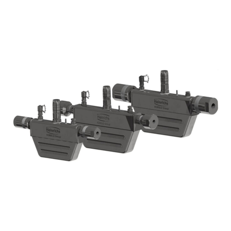
Kobold OVZ User manual

Operating Instructions
for
Oval Gear Wheel Meter
Model: OVZ
O
Or
rd
de
er
r
f
fr
ro
om
m:
:
C
C
A
A
B
Br
ri
ig
gg
gs
s
C
Co
om
mp
pa
an
ny
y
622 Mary Street; Suite 101; Warminster, PA 18974
Phone: 267-673-8117 - Fax: 267-673-8118
www.cabriggs.com

OVZ
page 2 OVZ K03/0416
1.Contents
1.Contents........................................................................................................2
2.Note ..............................................................................................................3
3.Regulation Use..............................................................................................3
4.Operating Principle........................................................................................4
5.Instrument Inspection....................................................................................4
6.Mechanical Connection.................................................................................5
7.Electrical Connection ....................................................................................6
7.1.General................................................................................................6
7.2.Evaluation electronics:.........................................................................7
7.3.Evaluation electronics: analogue output (..L..).....................................7
7.4.compact electronics:............................................................................7
7.5.Evaluation electronics: Pointer display (..Z300, ..Z340).......................8
8.Operation – evaluation electronics................................................................8
8.1.Frequency output.................................................................................8
8.2.Analogue output...................................................................................8
8.3.Compact electronics ............................................................................8
8.4.Pointer display (..Z300, ..Z340)............................................................8
9.Mechanical Operation...................................................................................9
10.Technical Information....................................................................................9
11.Pressure loss ..............................................................................................11
11.1.POM- plastic housing.........................................................................11
11.2.Aluminium housing.............................................................................12
12.Order Codes ...............................................................................................14
12.1.POM plastic housing..........................................................................14
12.2.Aluminium housing.............................................................................14
13.Maintenance ...............................................................................................15
14.Dismantling / Installation.............................................................................15
15.Recommended spare parts.........................................................................15
16.Dimensions .................................................................................................16
17.Declaration of Conformance .......................................................................20
Manufactured and sold by:
Kobold Messring GmbH
Nordring 22-24
D-65719 Hofheim
Tel.: +49(0)6192-2990
Fax: +49(0)6192-23398
Internet: www.kobold.com

OVZ
OVZ K03/0416 page 3
2.Note
Please read these operating instructions before unpacking and putting the unit
into operation. Follow the instructions precisely as described herein.
The devices are only to be used, maintained and serviced by persons familiar
with these operating instructions and in accordance with local regulations
applying to Health & Safety and prevention of accidents.
By usage in machines, the measuring unit should be used only when the
machines fulfil the EC-machine guidelines.
PED 2014/68/EU
In acc. with Article 4 Paragraph (3), "Sound Engineering Practice", of the PED
2014/68/EU no CE mark.
Diagram 8, Pipe, Group 1 dangerous fluids
3.Regulation Use
The model OVZ is an oval gear, positive displacement flowmeter which can be
used to measure and monitor the flowrate of viscous liquid (min. 10 mm²/s to
max. 800 mm²/s); (max. viscosity 1000 mm²/s upon request). Only measure
clean, non-abrasive liquids with adequate lubricating properties, and against
which the materials used in the sensor case are chemically resistant. Ferrite
particles may become deposited on the oval gears as they do contain permanent
magnets, - thus causing maloperation, or destruction of the oval wheel. We
recommend our model MF-RI... magnetic filter if the liquid contains a high
concentration of ferrous solids. In case of uncertainty, please consult your
supplier.
Material combinations
Model OVZ-..1.. OVZ-..2.. OVZ-..3.. OVZ-..4.. OVZ-..5..
Case POM POM Aluminium Aluminium Aluminium
Case cover POM PMMA PMMA PSU Aluminium
Axle Stainless steel 1.4301
Rotating sensing
targets Ceramics (Hall sensor versions) stainless steel (inductive
pickup versions)
Oval gears POM
Gaskets Standard: NBR; option: FPM or EPDM
max. operating
pressure 10 bar 10 bar 16 bar 16 bar 40 bar
max. medium
temperature -10 to +80 °C
max. ambient
temperature -10 to +60 °C
Filtration requirements max. 30 m

OVZ
page 4 OVZ K03/0416
4.Operating Principle
The OVZ oval wheel meter is a positive-
displacement flowmeter. The measuring
element comprises two toothed precision
oval gearwheels, which are driven by the
liquid inlet pressure. As the liquid rotates the
gears, a fixed quantity of liquid is transported
through the chambers for every turn of the
oval-wheel pair. Permanent magnets or
stainless steel pins are embedded in the oval
gear-wheels. The rotary gear motion is
converted to a pulse signal by electrical sensors externally fitted into the casing.
The pulse count is a measure of the flow rate. The signals are evaluated by
downstream electronics (optional).
5.Instrument Inspection
Instruments are inspected before shipping and sent out in perfect condition.
Should the damage to a device be visible, we recommend a thorough inspection
of the delivery packing. In case of damage, please inform your parcel
service/forwarding agent immediately, since they are responsible for damages
during transit.
Scope of delivery:
Oval wheel meter model: OVZ
Operating Instructions

OVZ
OVZ K03/0416 page 5
6.Mechanical Connection
Before installation:
Make sure that the actual flow rate corresponds with the measuring range of
the meter.
Make sure that the approved maximum operating pressure and operating
temperature of the meter are not exceeded.
Remove all transport restraints and ensure that there are no pieces of
packaging left in the meter.
Make sure that there are no welding beads, metal filings, or other pollutants, in
the piping. We strongly recommend you to connect a suitable filter in series
(filtration 30 m).
Installation:
The OVZ may be installed in any position; the liquid may flow in both
directions.
Inlet and outlet pipes are not required.
The connection threads may be sealed with sealing tape etc.
When installing the meters, make sure that the connection threads are not
subjected to large pressure or tensile loads. We recommend that you
mechanically secure the inlet and outlet line approximately 50 mm from the
connections.
If possible, you should check that the joint connections are sealed and leak-
free after mechanical installation.

OVZ
page 6 OVZ K03/0416
7.Electrical Connection
7.1. General
Important! Make sure that the voltages in your plant correspond
with the voltages on the nameplate.
Make sure that the electrical supply lines are dead.
Meters with connectors: solder the ends of the connection cable according
to the wiring diagram in the accompanying portable socket-outlets.
Meters with cable connections: connect the connection cable with the
supply cable.
Important! If the connections are incorrectly assigned, the sensor
may be seriously damaged.
DIN-43650 Plug (OVZ-...l401) Al-housing / Pg 9(OVZ-...l302)
Al-Housing / Round plug (OVZ-...l303)
PNP (OVZ-...l304) NAMUR (OVZ-...l305)

OVZ
OVZ K03/0416 page 7
1
2
34
+Vs
Signal
Out
n.c.
GND
+Vs
GND
7.2. Evaluation electronics:
Frequency output (OVZ-...F300; ...F3x0)
7.3. Evaluation electronics: analogue output (..L..)
3-wire (OVZ-...L303; ...L343) 3-wire, DIN 43650-plug (OVZ-...L443)
7.4. compact electronics:
(..C30r, ..C30M, ..C34P, ..C34N)
see instruction manual-addition for compact electronics with frequency output.
+Vs
Signal
Out
+Vs
GND
GND

OVZ
page 8 OVZ K03/0416
mA
+Vs
GND
Power
1
2
34
+Vs
Signal
Out
n.c.
GND
Plug M12
7.5. Evaluation electronics: Pointer display (..Z300, ..Z340)
Plug the portable socket-outlet into its mating connector on the meter.
8.Operation – evaluation electronics
8.1. Frequency output
The instruments are pre-adjusted. After electrical connection they are ready for
operation.
8.2. Analogue output
The instruments are pre-adjusted. After electrical connection they are ready for
operation.
8.3. Compact electronics
The instruments are pre-adjusted. After electrical connection they are ready for
operation.
For changing of setting refer
to operating manual for
compact electronic with frequency output
8.4. Pointer display (..Z300, ..Z340)
The instruments are pre-adjusted. After electrical connection they are ready for
operation.

OVZ
OVZ K03/0416 page 9
9.Mechanical Operation
To avoid pressure peaks, the flow medium should flow slowly into the meter.
Important! Pressure peaks arising from a sudden influx of liquid,
caused by solenoid valves, ball valves etc, may seriously damage the
meter (water hammer!). Ensure that the sensor is always filled with
medium when in the operating state.
Important! Vent the piping, to prevent large air bubbles in the sensor
chamber which may cause measuring errors, erratic flow reading and
can possibly seriously damage the bearings.
10. Technical Information
Viscosity range: 10 to 800 mm2/s
(option: 1000 mm2/s)
Ambient temperature: -10 °C to +60 °C
Medium temperature: -10 °C to +80 °C
Max. pressure: OVZ-..1, OVZ-..2: 10 bar
OVZ-..3, OVZ-..4: 16 bar
OVZ-..5 : 40 bar
Accuracy: ± 2.5 % f. s.
Filter mesh size: max. 30 µm
Material: combination/case/cover
OVZ-..1.. / POM /POM
OVZ-..2.. / POM /PMMA
OVZ-..3.. / aluminium /PMMA
OVZ-..4.. / aluminium /PSU
OVZ-..5.. / aluminium /aluminium
ovals wheels: POM
axles: stainless steel 1.4301
O-rings: NBR; option: FPM, EPDM
Sensor targets: oxide ceramic magnets
or stainless steel
Frequency range: 0.3-9 Hz to 2-57 Hz
Protection: IP 65 (..I401, I302, -I303,
L 443, ...Z 3x0)
IP 67 (all others)

OVZ
page 10 OVZ K03/0416
Electronics
Frequency output (...l401; ...l302; ...l303)
Power supply: 5-24 VDC
Power consumption: typically 10 mA
Pulse output: Hall effect sensor NPN
open collector, max. 15 mA
Electr. connection: connector socket DIN 43650 (...I401)
aluminium adapter box with cable
connection (...I302)
aluminium cover box with circular
connector M12x1 (...I303)
Frequency output (...l304)
Power supply: 18-30 VDC
Power consumption: typically 10 mA
Pulse output: PNP, asymmetrical, open collector
max. 120 mA
Electr. connection: 2 m PVC cable
Frequency output (...l305)
Power supply: nominal 8.2 VDC
Pulse output: Namur, asymmetrical,
max. approx. 3.5 mA (typ. 0.5 mA)
Electr. connection: 2 m PVC cable
Frequency output (...F300)
Power supply: 12-28 VDC
Power consumption: 10 mA
Pulse output: PNP, open collector, max. 25 mA
Electr. connection: connector M12x1
Frequency output with frequency divider (...F3X0)
Power supply: 24 VDC
Power consumption: 15 mA
Pulse output: PNP, open collector, max. 25 mA
Electr. connection: connector M12x1
Divisional factor: acc. to customer specification
Analogue output (...L303; ...L343, ...L443)
Power supply: 24 VDC ± 20 %
Output: 4-20 mA, 0-20 mA, 3-wire
Max. load: 500 ohm
Electr. connection: connector M12x1 or DIN 43650
Option: plug-on display AUF-3000
(with DIN connector only)

OVZ
OVZ K03/0416 page 11
Compact electronics
Display: 3-digit LED
Analogue output: (0) 4...20 mA adjustable, max. 500 W
Switching outputs: 1 (2) semiconductor PNP or
NPN, factory setting
Contact operation: N/C, N/O programmable
Setting: via 2 keys
Power supply: 24 VDC ± 20 %, 3-wire, approx. 100 mA
Electr. connection: connector M12x1
Pointer indication with analogue output
Housing: aluminium
Indication: moving coil instrum. 240 ° indication
Power supply: 24 VDC ± 20 %
Output: 0-20 mA or 4-20 mA, 3-wire
Max. load: 250 ohm
Electr. connection: connector M12x1
11. Pressure loss
11.1. POM- plastic housing
OVZ-02... OVZ-04...

OVZ
page 12 OVZ K03/0416
OVZ-15... OVZ-30...
11.2. Aluminium housing
OVZ-02... OVZ-04...

OVZ
OVZ K03/0416 page 13
OVZ-15... OVZ-30...

OVZ
page 14 OVZ K03/0416
12. Order Codes
12.1. POM plastic housing
(Example: OVZ-02 1 G2 N I401)
Rated measuring range (L/min)
1
)
(for different viscosities)
Imp./
Liter2)4) Model Material/
coverl Connection Gaskets Electrical transducer
10 mm²/s 100 mm²/s 320 mm²/s 800 m²/s
0.3-8.0 0.3-8.0 0.2-5.0 0.1-2.0 408.5
OVZ-02..
..1..= POM
..2..= PMMA
..G2..= G 1/4
..N2..= 1/4 NPT ..N..= NBR
(standard)
..V..= FPM
..E..= EPDM
Frequency output
..I401= frequency output NPN, DIN connector 43650
..I302= frequency output NPN, cable connection
..l304= frequency output PNP, 2 m PVC cable
..l305= frequency output Namur, 2 m PVC cable
..F300= frequnecy output PNP, connector M12x1
..F3X0= frequency divider adjusted PNP, connector M12x1
Analogue output
..L303= 0-20 mA output, 3-wire, M12x1connector
..L343= 4-20 mA output, 3-wire, M12x1connector
..L443= 4-20 mA output, 3-wire, DIN connector
Compact electronic3)
..C30R= LED-display, 2xopen collector, PNP, connector M12x1
..C30M= LED-display, 2xopen collector, NPN, connector M12x1
..C34P= LED-display, 4-20 mA, 1x op.coll.,PNP,connector M12x1
..C34N= LED-display, 4-20 mA, 1xop.coll.,NPN, connector M12x1
Pointer indication, 240° 3)
..Z300= 240°-pointer indication, 0-20 mA, connector M12x1
..Z340= 240°-pointer indication,4.20 mA, connector M12x1
0.4-10.0 0.4-10.0 0.3-8.0 0.15-4.0 224 OVZ-04.. ..G2..= G 1/4
..N2..= 1/4 NPT
1.0-25.0 1.0-25.0 1.0-25.0 0.4-10.0 52.5 OVZ-15.. ..G4..= G 1/2
..N4..= 1/2 NPT
1.6-40.0 1.6-40.0 1.6-40.0 0.95-24.0 28 OVZ-30.. ..G5..= G 3/4
..N5..= 3/4 NPT
1) Maximum pressure loss at maximum rated flow is 1 bar
2) Hz=Imp./Liter x L/min/60
3) Please specify flow direction in writing
4) At the electronic option “frequency output” the actual pulse ratio is stated on the type label
12.2. Aluminium housing
(Example: OVZ-02 3 G2 N I401)
Rated measuring range (L/min)
1)
(for different viscosities)
Imp./
Liter 2)4) Model Material/
cover Connection Gaskets Electrical transducer
10 mm²/s 100 mm²/s 320 mm²/s 800 mm²/s
0.3-8.0 0.3-8.0 0.25-6.6 0.1-3.0 396 OVZ-02..
..3..= PMMA
..4..= PSU
..5..= Alu
..G2..= G 1/4
..N2..= 1/4 NPT ..N..= NBR
(Standard)
..V..= FPM
..E..= EPDM
Frequency output
..I401= frequency output NPN, DIN connector 43650
..I302= frequency output NPN, cable connection
..l304= frequency output PNP, 2 m PVC cable
..l305= frequency output Namur, 2 m PVC cable
..F300= frequnecy output PNP, connector M12x1
..F3X0= frequency divider adjusted PNP, connector M12x1
Analogue output
..L303= 0-20 mA output, 3-wire, M12x1connector
..L343= 4-20 mA output, 3-wire, M12x1connector
..L443= 4-20 mA output, 3-wire, DIN connector
Compact electronic3)
..C30R= LED-display, 2xopen collector, PNP, connector
M12x1
..C30M= LED-display, 2xopen collector, NPN, connector
M12x1
..C34P= LED-display, 4-20 mA, 1x op.coll.,PNP,connector
M12x1
..C34N= LED-display, 4-20 mA, 1xop.coll.,NPN, connector
M12x1
Pointer indication, 240° 3)
..Z300= 240°-pointer indication, 0-20 mA, connector M12x1
..Z340= 240°-pointer indication,4-20 mA, connector M12x1
0.4-10.0 0.4-10.0 0.4-10.0 0.25-4.5 203 OVZ-04.. ..G2..= G 1/4
..N2..= 1/4 NPT
1.0-25.0 1.0-25.0 0.9-23.0 0.5-12.5 46.5 OVZ-15.. ..G4..= G 1/2
..N4..= 1/2 NPT
1.6-40.0 1.6-40.0 1.3-33.5 0.8-20.0 26 OVZ-30.. ..G5..= G 3/4
..N5..= 3/4 NPT
1) Maximum pressure loss at maximum rated flow is 1 bar
2) Hz = Imp./Liter x L/min/60
3) Please specify flow direction in writing
4) At the electronic option “frequency output” the actual pulse ratio is stated on the type label
Digital indicators and transducers to this oval wheel flow meter please see end of brochure.
Plug-on display
for Model OVZ... L4 ... (with 4-20 mA output and DIN-connector)
Description Order number
3-digit LED, plug-connection DIN 43 650
3-wire, power supply with analogue output AUF-3000

OVZ
OVZ K03/0416 page 15
13. Maintenance
The meter requires no maintenance if the measured medium is not contaminated.
Should it be necessary to clean the meter, the case cover can be easily removed
to gain access to, and clean, the inside of the case (see Sec. 12. Dismantling
/Installation).
14. Dismantling / Installation
Dismantling:
Drain piping.
Loosen cover screws and remove cover and O-ring.
Mark the position of the gearwheels relative to one another with a pencil.
Remove the pair of oval gearwheels and clean parts with care; do not scratch
the sealing faces.
Caution: Do not remove the gearwheel position marking!
Installation:
Install the pair of oval gearwheels; note identifying marking.
Rotate gearwheels a number of times: they should not disengage.
Insert O-ring; replace cover and firmly tighten screws crosswise.
15. Recommended spare parts
1.0 Pair of oval gearwheels
2.0 NBR, FPM, or EPDM O-ring
3.0 POM, PMMA, PSU, or AL cover
Always specify the meter model when ordering spare parts.

OVZ
page 16 OVZ K03/0416
16. Dimensions
OVZ-...l401
G
[mm] H
[mm] F [mm]
..1.. ..2.. ..3/ 4.. ..5..
OVZ-02... 68 68 45 45 43,5 41
OVZ-04... 68 68 49 49 47 44,5
OVZ-15... 99 99 71 73 71 66
OVZ-30... 119 119 84,5 87,5 86 79,5
OVZ-...l302, OVZ-...l303
G
[mm] H
[mm] F [mm]
..1.. ..2.. ..3/ 4.. ..5..
OVZ-02... 68 68 45 45 43,5 41
OVZ-04... 68 68 49 49 47 44,5
OVZ-15... 99 99 71 73 71 66
OVZ-30... 119 119 84,5 87,5 86 79,5

OVZ
OVZ K03/0416 page 17
OVZ-...l304, OVZ-...l305
PNP NAMUR PNP/ NAMUR
A [mm] B [mm] A [mm] B [mm] G [mm] H [mm]
OVZ-02.. 21,5 13,5 16,5 13,5 68 68
OVZ-04.. 21 14 16 14 68 68
OVZ-15.. 19 16 14 16 99 99
OVZ-30.. 17 18 12 18 119 119

OVZ
page 18 OVZ K03/0416
OVZ-...L3... OVZ-...F3... OVZ-...L443 with AUF-3000
OVZ with frequency or analogue output: overview
Plastic housing (POM)
Description Dimension
A Dimension
B Dimension
C
OVZ-02 1 = POM 13 45 68
OVZ-02 2 = PMMA 13 45 68
OVZ-04 1 = POM 13.7 49 68
OVZ-04 2 = PMMA 13.7 49 68
OVZ-15 1 = POM 15.65 71 99
OVZ-15 2 = PMMA 15.65 73 99
OVZ-30 1 = POM 17.6 84.5 119
OVZ-30 2 = PMMA 17.6 87.5 119
Aluminium housing (ALU)
Description Dimension
A Dimension
B Dimension
C
OVZ-02 3 = PMMA 11.5 43.6 68
OVZ-02 4 = PSU 11.5 43.6 68
OVZ-02 5 = ALU 11.5 41.1 68
OVZ-04 3= PMMA 11.5 47 68
OVZ-04 4 = PSU 11.5 47 68
OVZ-04 5 = ALU 11.5 44.5 68
OVZ-15 3= PMMA 13.35 71 99
OVZ-15 4 = PSU 13.35 71 99
OVZ-15 5 = ALU 13.35 66 99
OVZ-30 3= PMMA 15.75 86 119
OVZ-30 4= POM 15.75 86 119
OVZ-30 5= PMMA 15.75 79.5 119

OVZ
OVZ K03/0416 page 19
OVZ with compact electronics: overview
Plastic housing (POM)
Description Dimension
A Dimension
B Dimension
C
OVZ-02 1 = POM 19.525 45 68
OVZ-02 2 = PMMA 19.525 45 68
OVZ-04 1 = POM 16.95 49 68
OVZ-04 2 = PMMA 16.95 49 68
OVZ-15 1 = POM 21.125 71 99
OVZ-15 2 = PMMA 21.125 73 99
OVZ-30 1 = POM 23.2 84.5 119
OVZ-30 2 = PMMA 23.2 87.5 119
Aluminium housing (ALU)
Description Dimension
A Dimension
B Dimension
C
OVZ-02 3 = PMMA 19.525 43.6 68
OVZ-02 4 = PSU 19.525 43.6 68
OVZ-02 5 = ALU 19.525 41.4 68
OVZ-04 3= PMMA 19.525 47 68
OVZ-04 4 = PSU 19.525 47 68
OVZ-04 5 = ALU 19.525 44.5 68
OVZ-15 3= PMMA 21 71 99
OVZ-15 4 = PSU 21 71 99
OVZ-15 5 = ALU 21 66 99
OVZ-30 3= PMMA 23.025 86 119
OVZ-30 4= POM 23.025 86 119
OVZ-30 5= POM 23.025 79.5 119
OVZ-…C3… OVZ-…Z3…

OVZ
page 20 OVZ K03/0416
17. Declaration of Conformance
We, Kobold Messring GmbH, Hofheim-Ts, Germany, declare under our sole
responsibility that the product:
Oval Gear Wheel Meter Model: OVZ-...
to which this declaration relates is in conformity with the standards noted below:
EN 61000-6-2:2006
Electromagnetic compatibility (EMC) - Part 6-2: Generic standards - Immunity for
industrial environments
Also the following EC guidelines are fulfilled:
2014/30/EU EMC Directive
2011/65/EU RoHS (category 9) industrial monitoring and control
instruments, compliant, no CE-marking for the transitional
period until 2017
Hofheim, 27. April 2016
H. Peters M. Wenzel
General Manager Proxy Holder
Table of contents
Other Kobold Measuring Instrument manuals

Kobold
Kobold KDF-9 User manual

Kobold
Kobold ZOE User manual

Kobold
Kobold DPL-IP Series User manual

Kobold
Kobold VKM Series User manual

Kobold
Kobold VKG User manual

Kobold
Kobold MAN-SD series User manual

Kobold
Kobold DON-05Lx User manual

Kobold
Kobold DPT Series User manual

Kobold
Kobold Henschen MAN-SF Series User manual

Kobold
Kobold MAN-SD series User manual

Kobold
Kobold OMH-15 User manual

Kobold
Kobold MIK User manual

Kobold
Kobold KAL-K User manual

Kobold
Kobold SZM User manual

Kobold
Kobold NRF User manual

Kobold
Kobold DOG-4 User manual

Kobold
Kobold DOG-4 User manual

Kobold
Kobold DOG Series User manual

Kobold
Kobold DAG-A34 User manual

Kobold
Kobold DAG-M1V Series User manual