Shape of nozzle
insertion port
6. Installation, Wiring and Tubing
6.1 Installation
CAUTION
DTY-ELK01-L (low-dust type) uses clean room packaging. Always open the
packaging in a clean room environment.
A nozzle is not included with the product (exception: installed in the air-saving type).
Separately purchase a nozzle matching your utilization.
Nozzles are made specifically for each type. Always use the right nozzle for each
type.
1) Attach the nozzle to the m ain unit, and use the pin provided with the n ozzle
to fix it to the main unit.
* To replace the nozzle, pull out the pin and then rem ove the nozzle.
WARNING
Check that the nozzle is securely inserted and securely held in place by the pin. If
not perfectly set, the nozzle could come loose during use, damaging the product and
equipment.
CAUTION
The nozzle insertion part is made in a D-shaped cut to prevent rotation. When
attaching, align the main unit nozzle insertion port with the nozzle insertion part.
2) W hen using the mounting bracket for in stallation, use the two mounting
bracket screws (enclosed with the pac kaging) to m ount the mounting
bracket to the m ain unit.
CAUTION
Tightening torque for mounting the bracket to the main body should be 50 N・cm
or less.
3) Use the mounting h oles on the side of the m ain unit (3-3.4) or the mounting
holes in the mounting bracket ( 4-3.4) to fix t he product in place.
* Provide the m ounting screw s separately.
4) If using a tube, insert th e tube firmly all the w ay to the base of the nozzle.
5) If using a nozzle and tube capable of adjusting the ionized air blow direction,
fix the n ozzle so that the ionized air blow port is point ed toward the static
charge removal target.
6) If using a tube-tip nozzle, firmly insert the tube-tip nozzle into the tube, and
use the brac ket provided to fix it in place.
* For details, refer to the Instruction Manual provided with the tube-tip nozzle.
CAUTION
As piezoelectric ceramic is built into the main unit, do not apply shocks due to
dropping or vibration, etc. Such action could result in product malfunction.
The various tubes used for the standard nozzle are consumable items that require
periodic replacement.
When bending the bender nozzle, maintain the base of the bender nozzle in place.
The main body could be damaged.
Do not use nozzles not specifically designed for the unit. Also, do not make
modifications to the nozzle. Such action could be the cause of product
malfunctions, function shutdown, or damage.
Do not install in locations prone to condensation, or subject to large humidity and
temperature swings. The product could be subjected to damage.
<W hen using the nozzle unit for the bender nozzle>
1) Rem ove the tip of the bender nozzle.
2) Always tighten the various nozz le units sec urely to the bender nozzle.
CAUTION
Hold the pipe portion securely when removing the tip of the bender nozzle.
The recommended tightening torque for the nozzle unit used for the bender
nozzle is 30 N・cm.
3) To adjust the direction of the bar n ozzle unit (DT RY-A DN -□00B) ionized air
blow port, loosen nut B.
To adjust the direction of the flat nozzle unit (DT RY -ADN-FT01) attach the
ionized air blow port at the tip, and u se the lock n ut to fix in place.
CAUTION
When loosening nut B, be sure that nut A is fixed in place, and check that no
force is being applied to the bender nozzle.
6.2 Wiring
1) Use the pow er signal cable provided, and connect as sh own in the figure
below.
If taking power from input 100VAC, use the AC adaptor (DTY-ZKPS), sold
separately.
CAUTION
Securely connect the ground wire (with a grounding resistance of 100Ωor less).
Otherwise, ionizer performance may not be adequate.
Securely insert the connector.
Contact capacity for each output is 24V 50 mA MAX. Check the capacity of the
connected equipment before use.
When selecting a power supply for use with this product, always use one that has
been certified by the EU Notified Body (as a limited power source defined in
IEC/EN60950-1 or IEC/EN61010-1), or the optional AC adapter.
0VDC, F.G, nozzle and mounting bracket are connected to the internal circuit.
Use a mechanical switch, photo coupler, or relay for external input. If the
grounding potential of the external device to be used and the grounding potential
of this product are different, the external device should have an insulated on/off
procedure for the 0V line.
I/O Circuit Diagram
*①-⑦show the main unit pin number.
* Note in parenth eses ( ) shows the lead wire color in the pow er signal cable.
* Use a n o-voltage contact point or NPN open collector to connect ③H.V OFF.
(when ②0VDC short ed, discharge O FF)
* W hen discharge OFF (when ③H.V OFF and ②0VDC shorted), H.V LED
goes OFF.
No. Signal Function
①24VDC Power input 24VDC±5%
②0VDC Power 0V and output 0V
③H.V OFF Discharge OFF when shorted at ②
④ALARM NC Contact point output when performance
malfunction occurs
(b contact point 24VDC 50 mA MAX)
⑤ALARM NO Contact point output when performance
malfunction occurs
(a contact point 24VDC 50 mA MAX)
⑥CHECK NO Contact point output when abnormal
discharge occurs
(a contact point 24VDC 50 mA MAX)
⑦F.G. Functional earth (with a grounding
resistance of 100Ωor less)
CAUTION
The abnormality output circuit of this product will be active about one second after the
power is switched on. Sufficient care should be taken to design an error detection circuit
during installation.
When the power to the main unit of the ionizer is switched ON immediately after being
switched OFF, an abnormality output may occur. When performing such an operation, be
sure to wait for a period of at least one second after switching off.
When the ionizer main unit is switched OFF, an abnormality output may occur. Pay careful
attention to the design of the error detection circuit not to detect the ionizer’s abnormality
output for a one-second period after the power supply to the ionizer main unit is switched
OFF.
6.3 Air Tubing
1) Connect air tubes (outer diameter 6 m m) to the DTY-ELK01 and
DTY-ELK01-S main unit air fittings.
For DTY-ELK01-L, use fittings that match the tubing used (port size: Rc1/8).
2) Use a regulator to connect the air tu be to the air sou rce.
WARNING
Always supply air before switching ON the power, and use within the specified
pressure range.
CAUTION
Although the DTY-ELK01-L (low-dust type) is subjected to clean-room cleaning
and packaging using clean air at time of shipping, the effects of vibration, etc.,
during transport can generate particles. Flush out the unit and clean it thoroughly
before commencing initial use.
For connection to or replacement of a DTY-ELK01-L (low-dust type) fitting,
proceed by holding the female screw (Rc1/8) hexagonal part in position.
Application of excessive force to the main unit could cause damage to the main
unit.
7. Operating
7.1 Steps When Starting Operation
1) Check that the nozzle and discharge needle unit are c o rrectly connected to
the ionizer.
2) Check the ionizer wiring and air tubing.
3) Supply air to the unit from the air equipment that is being used.
4) Sup ply 24VDC pow er to the unit. The P OW ER LED and H.V LED on th e
unit light up and electrostatic elim ination begins.
* If the optional p ower adapter is used, supply 100-240VAC, 50/60 H z.
* W hen using external controls (H.V OFF) to control the unit, the H.V LED
goes OFF w hen discharge is OFF.
* Use the input power side (24V DC side) to sw itch power ON/OFF.
WARNING
Take soundproof measures, such as wearing earplugs, when working at close
proximity to the unit.
7.2 Steps When Stopping Operation
1) Stop the supply of pow er to the unit.
2) Stop the supply of air.
CAUTION
If the POWER LED is not illuminated or if the CHECK LED or ALARM LED lights up,
immediately shut off the power and air, and see “6. Installation, Wiring and Tubing” in
this manual. If problems still do not resolve, see “8. Maintenance” and “9.
Troubleshooting” in this manual.
8. Maintenance
If the discharge needle is soiled, the electrostatic elimination effects w ill be
reduced. Periodically clean the discharge needle and surrounding area t o
maintain perform anc e.
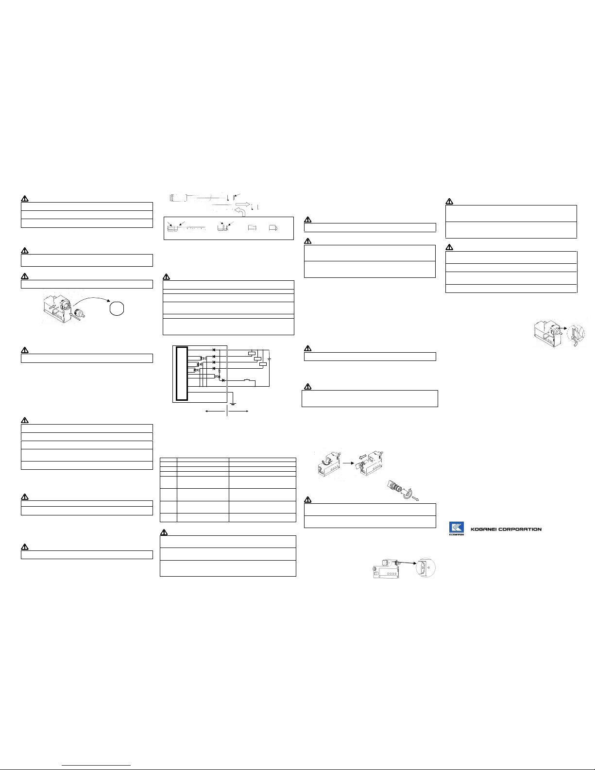
<Discharge needle u nit cleaning method >
1) Rotate the discharge needle unit counterclockwise, and pull it from the main
unit.
2) R otate the disch arge needle unit bushing
counterclockwise, and remove the bushing.
CAUTION
Do not apply excessive force when removing the bushing from the discharge
needle unit.
The discharge needle unit could be damaged.
When replacing the discharge needle unit, use the specified discharge needle
unit. Discharge needle units are specifically designed for each type.
You can determine the correct discharge needle unit by its color.
3) W hen the discharge needle unit has been rem oved, use a cotton swab
soaked in anhydrous alcohol (IPA) to clean the discharge needle and
bushing.
4) After drying the unit carefully with an hydrous alcohol, reassemble the
discharge needle unit ont o the
main unit in reverse s equenc e to
rem oval.
At this time, rotate until the ∆
mark on the side of the main unit
is aligned with the ∆mark on the
discharge n eedle unit.
WARNING
As the tip of the discharge needle is very sharp, care is needed when removing
the discharge needle and during cleaning. The needle tip can cause injury. In
addition, be extremely careful to avoid bending or breaking the discharge needle.
Performance will be affected.
Securely attach the bushing and the discharge needle unit.
If not securely fixed in place, performance will be affected, and the discharge
needle unit may become loose during use, causing damage to the product and
equipment.
CAUTION
To maintain performance, be sure to perform cleaning of the discharge needle and
the surrounding area periodically. Performance will be affected, and lack of cleaning
may cause damage to equipment and workpieces.
When performing maintenance, always disconnect the connection cables before
proceeding.
When using alcohol or similar substances, make sure that there is adequate
ventilation. In addition, always thoroughly dry off the alcohol after using it for
cleaning, and check that none has spilled on to the main unit.
Because it can result in damage to the main unit, absolutely never use a wire
brush for cleaning.
<Main unit filter replacement method>
For DTY-ELK01-S, a filter is installed on th e outside air intake port.
A dirty filter will result in reduced outside air intake efficiency, and static charge
rem oval perform anc e will becom e in adequat e.
Replace the filter if it has bec om e dirty.
1) Rem ove the pin fixing th e nozzle in place.
2) Pull out the filter in the nozzle direction.
If difficult to rem ove, use a precision
screwdri ver or tweezers.
3) Insert the new filter so that it slips in from the
nozzle direction, and then remou nt the pin.
9. Troubleshooting
If product operation appears to be abnormal, immediately shut off the power to
the m ain unit, disconnect the connection cable from the m ain unit’s power
connection terminal, and check the ite ms in this section. If the abnormal
situ ation continues, it may m ean that a breakdown has occurred. Contact the
outlet (the agency) at w hich you purchased the product, or the n earest
Koganei service station.
The POWER LE D does not light up.
→ Verify that the wiring and power source are connected correctly.
The POWER LE D lights up but the H.V LED does not.
→ Verify that the H.V OFF terminal is not shorted.
CHECK LED and AL ARM LED are illuminated.
→ Verify that the unit is securely grounded.
→ Verify whether the discharg e needle is soiled or dam aged, and wheth er the
surrounding area is soiled. If it is soiled, see “8. Maintenance” in this manual,
and perform maintenanc e or replacem ent of the discharg e needle unit.
No electrostatic elimination effect
→ Verify that ionized air is blown to the object elim inating static electricity.
→ Verify whether the discharg e needle is soiled or dam aged, and wheth er the
surrounding area is soiled. If it is soiled, see “8. Maintenance” in this manual,
and perform maintenance or replacement of the discharge needle unit.
Any oth er abnormal condition
If any other abnorm al condition has been observed, immediately turn off the
pow er from the product, and please c ontact the outlet (the agency) at which
you purchased the p rod uct, or the nearest Koganei service station.
10. Consumables and Optional Parts
・Discharge needle unit: DTY-ZKEM (standard type: White)
DTY-ZKEMS (air-saving type: Light blue)
DTY-ZKEML (low -dust type: Gray)
・Air-saving type replacem ent filter: DTY-ZKFS (5 filters/ set)
・AC adapter: DTY-ZKPS
・Controller: DTY-ZK CR
・Controller unit: DTY-ZKCRU (Unit with solenoid valve)
JUST CONSULT US:
KOGANEI CORP ORATION OVERSEAS DEPARTMENT
3-11-28, Midoricho, Kogan ei-shi, Tokyo, 184-8533, Japan
TEL:+81- 042-383-7271 FAX:+81- 042-383-7276
Website: http://www.koganei.co.jp
The specifications or the app earance of this product are subject to change any
tim e without prior notice.
X903918 Rev1.5
Tube-tip
DTRY-ADN-FT01
DTRY-ADN-□00B