2
1286337-W2-E
Important Information
Products manufactured by Kohler Mira Ltd are designed to be safe,
provided that they are installed, used and maintained in good working
order, in accordance with our instructions and recommendations.
Follow all warnings, cautions and instructions contained in this guide,
and on, or inside the product. Failure to follow the instructions provided
with this product will invalidate the guarantee.
WARNING!
TO REDUCE THE RISK OF FIRE, ELECTRIC SHOCK OR INJURY:
Installation
1. Installation of the User Interface and the Remote On/Off (if
supplied) must be carried out in accordance with these instructions
by qualied, competent personnel. Read all instructions before
commencing installation.
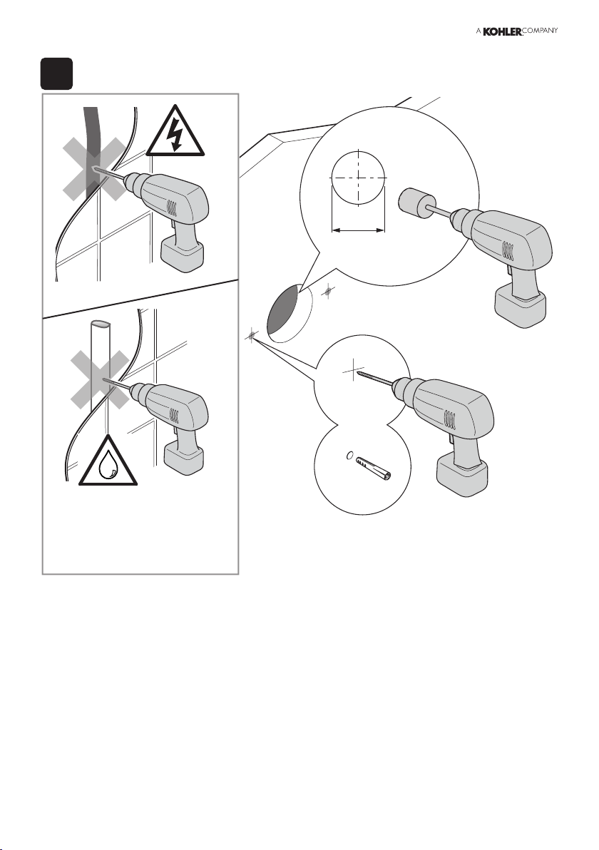
Note! Cables routed through wall cavities, chased into solid walls,
directed under baths or in attic spaces must be tted in such a way
so that they can later be removed.
To facilitate this appropriate cable conduit / trunking must be used
at all times. The conduit / trunking must be at least 20mm diameter
/ square to allow for safe removal of the connectors. Failure to
do so may result in an inability to carry out any maintenance or
service. Safe and easy access to the product should be available
at all times.
2. Isolate the electrical and water supplies before commencing
installation.
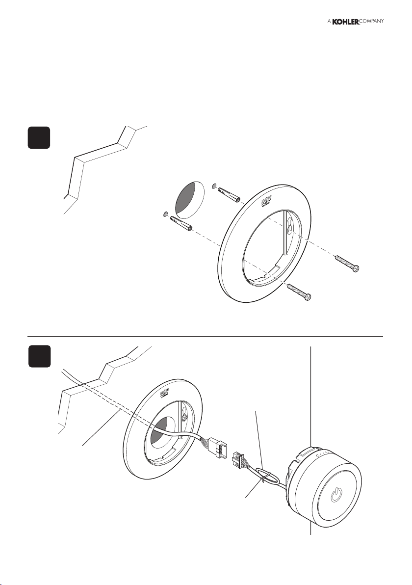
3. Mains connections are exposed when the valve module cover is
removed.
4. DO NOT perform any unspecied modications, drill or cut holes
in the product other than instructed by this guide. When servicing
only use genuine Kohler Mira replacement parts.
5. DO NOT modify or extend the cables supplied with the product.