Kohler 15-60REOZK User manual

TT-1701 2/17
INSTALLATION INSTRUCTIONS
Original Issue Date: 2/17
Model: 15--60REOZK with Decision-Makerr3000 Controllers Only
Market: Industrial
Subject: Electronic Governor Kit GM90661-KP1
Introduction
The electronic governor kit provides isochronous
governing by using the signal over CAN to control the
current input to the actuator. This kit is intended for use
with units having the Decision-Makerr3000 controller
only.
Note: The electronic governors are shipped
unprogrammed and have no manual
adjustments. After installation, the governor
requires downloading software and changes to
the default settings.
The electronic governor kit includes an:
DActuator (locate on top of injection pump).
DElectronic governor (locate inside the junction box).
See Figure 1 for specifications.
Specs
Supports CAN/J1939 bus interface
Operating Temperature -- 4 0 _to 85_C(--40_to 185_F)
Power Input 9--30 VDC,
Reverse polarity protected
Output to Actuator Pulse--width--modulated, 6 A max.
Auxiliary Outputs 200 mA max.
Figure 1 Governor Specifications
Read the entire procedure before beginning. Install the
software onto a PC. Carefully follow these instructions
and any additional instructions that appear on the
screen during the download procedure. The
instructions provided here assume you know how to
operate a PC.
Loading incorrect or incomplete files may cause
permanent damage to the governor controller’s logic
circuit board. Verify that the downloaded files contain
the settings for your specific generator set and engine.
Do not attempt to modify the data files.
Required Tools and Equipment
Obtain the APECS Programming Interface Harness Kit
GM100177-KP1. See Figure 2.
Figure 2 Interface Harness
A PC with SiteTechtsoftware is required to make the
electronic governor functional. Use your SecurID to
access Kohler Power Resource Center, click on the
TechTools button, and follow the instructions to
download the files. Refer to TP-6701 SiteTecht
Software Operation Manual for more information.
A PC with Kohler ACT Tool software is also required
to make the electronic governor functional. Use your
SecurID to access Kohler Power Resource Center, click
on the TechTools button, and follow the instructions to
download the files.
Have two 8 mm wrenches available for adjusting the
throttle arm, a TP Torx Plusrdriver for removing the
actuator cover, and a flex joint/universal joint for
installing the actuator.
Torx Plu s ris a registered trademark of AcumentrIntellectual
Properties, LLC.

2TT-1701 2/17
Safety Precautions
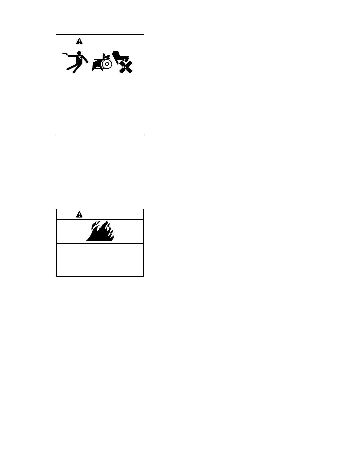
Accidental starting.
Can cause severe injury or death.
Disconnect the battery cables before
working on the generator set.
Remove the negative (--) lead first
when disconnecting the battery.
Reconnect the negative (--) lead last
when reconnecting the battery.
WARNING
Disabling the generator set. Accidental starting can
cause severe injury or death. Before working on the
generator set or equipment connected to the set, disable the
generator set as follows: (1) Press the generator set off/reset
button to shut down the generator set. (2) Disconnect the
power to the battery charger, if equipped. (3) Remove the
battery cables, negative (--) lead first. Reconnect the negative
(--) lead last when reconnecting the battery. Follow these
precautions to prevent the starting of the generator set by the
remote start/stop switch.
Fire.
Can cause severe injury or death.
Do not smoke or permit flames or
sparks near fuels or the fuel system.
WARNING
Servicing the fuel system. A flash fire can cause severe
injury or death. Do not smoke or permit flames or sparks near
the fuel injection system, fuel line, fuel filter, fuel pump, or other
potential sources of spilled fuels or fuel vapors. Catch fuels in
an approved container when removing the fuel line or fuel
system.
Installation Procedure
1. Remove the generator set from service.
1.1 Press the generator set OFF/RESET button to
shut down the generator set.
1.2 Disconnect the power to the battery charger, if
equipped.
1.3 Disconnect the generator set engine starting
battery(ies), negative (--) lead first.
1.4 If equipped with an enclosure, remove enclosure
doors as needed to service the engine.
2. Install the actuator.
2.1 Before removing the mechanical governor head and
replacing it with the actuator (324516), clean the
surrounding area. Clean outside of the fuel injection
pump with dry compressed air before removing the
governor control cover. Place a suitable container
underneath the fuel injection pump to catch any fuel
that may spill when removing the governor control
cover.
Note: Dispose of all waste materials (engine oil, fuel,
filter, etc.) in an environmentally safe manner and
in accordance with all applicable laws.
2.2 Remove lead 70 from the existing mechanical
governor and tape the end of the lead and tuck
inside the plastic conduit.
2.3 Remove the fuel return line and the return line
connector assembly from the governor cover using
care not to allow dirt to enter the injection pump.
Remove and discard the return line connector
O-ring. Set aside the return line connector.
2.4 Loosen the three cover screws.
Note: A universal joint or flex socket is needed to
remove the rear-most screw.
2.5 Remove the governor control cover assembly (see
the following NOTE). Save the screws for later use.
See Figure 3.
Note: When the actuator is fully loose, have rags handy
as there will be fuel spilled from the reservoir.
Figure 4 shows the fuel rack/metering assembly
with the cover removed. The fork on the
electronic governor cradles this arm and moves it
to govern the speed. On a mechanical governor,
the solenoid defaults to an extended position
when not powered so that it pushes against the
spring tension; this metering assembly turns off
fuel. Take great care when replacing the
actuator. If the linkage is missed, the engine may
“runaway” as it would be in the full-fuel position. If
you push on this arm with your finger, you’ll see it
actuate and feel the tension.

TT-1701 2/17 3
Figure 3 Actuator Screws (qty. 3)
Figure 4 Actuator
Note: To prevent any damage, properly install the
metering valve drive coupling to the governor
linkage on the pump as described below.
2.6 Install the new cover seal (part of the actuator
components) into the groove of the integrated
actuator cover assembly.
2.7 Position the actuator head similar to Figure 5.
Slightly lift the front portion of the actuator cover.
2.8 Carefully slide the integrated actuator cover
toward the rear of the pump body until the
mounting holes between the integrated actuator
cover and pump body begin to align. Once in
place, you’ll see that the actuator is offset from the
mounting holes and feel that there is spring
tension pushing on the cover. If you push on the
cover, you’ll feel the tension which means that
there is good contact with the linkage. See the
slight offset in Figure 6.
2.9 Reuse the three cover mounting screws to
assemble the integrated actuator cover to the
pump body. Tighten the screws to 4--5 Nm
(35--45 in. lb.).
Note: A universal joint or flex socket is needed to install
the rear-most screw.
2.10 Locate the 2 leads in the engine harness near the
governor. These leads may be yellow and orange
or blue and green (depending on the generator set
model).
Figure 5 Actuator (Cover Design Similar)
Figure 6 Actuator (Cover Design Similar)
2.11 Connect the two leads to the two screws at the
actuator. It doesn’t matter which leads attach to
which screws.
2.12 Install a new O-ring (part of the actuator
components) on the return line connector
assembly. Apply a light coating of all-purpose
grease to the O-ring and install the connector.
Tighten to 4.9--6 Nm (43--53 in. lb.).
2.13 Install the fuel return line to the return line
connector.
3. Remove the air cleaner assembly.
Removal of the air cleaner assembly is required as a
means to shut down the engine should the actuator
linkage be improperly installed in Step 2.
Note: Controllers are factory adjusted to minimum
RPM. However, for safety, the engine should be
capable of being disabled if an overspeed
condition should occur.
Note: The best practice when replacing the actuator is
to remove the air cleaner piping such that the
junction box cover can be used to cut off air
supply to the engine in the event of a runaway due
to improper governor installation.

4TT-1701 2/17
3.1 Remove the air cleaner cover.
3.2 Remove the air cleaner element.
3.3 Remove the air cleaner base.
4. Install the governor kit.
4.1 Remove the junction box cover and mount the
electronic governor (GM90652) in the junction box
using 2 each screws (M933-06030-60, plain
washers (M125A-06-80), and nuts (M6923-06-80.
See Figure 7 (15--30REOZK) or Figure 8
(40--60REOZK).
4.2 Connect governor harness GM90770 to terminal
strip TB12 in the junction box using Figure 9. Do
not plug the governor harness connector to the
electronic governor at this time.
GM90661-1
1. Actuator (324516)
2. Screws (M933-06030-60 qty. 2), nuts (M6923-06-80 qty. 2), and washers (M125A-06-80 qty. 2)
3. Electronic governor (GM90652)
4. Governor harness (GM90770)
1
2
3
4
Figure 7 Installed Electronic Governor Kit. 15--30REOZK
1. Actuator (324516)
2. Electronic governor (GM90652),
3. Screws (M933-06030-60 qty. 2), nuts (M6923-06-80 qty. 2), and washers (M125A-06-80 qty. 2)
4. Governor harness (GM90770)
1
2
GM90661-2
3
4
Figure 8 Installed Electronic Governor Kit, 40--60REOZK

TT-1701 2/17 5
TT-1701
GM90770
Figure 9 Electronic Governor Wiring Diagram and Wiring Harness GM90770, Typical
4.3 Connect the grey male connector on the interface
harness to the grey receptacle on the electronic
governor. See Figure 10.
4.4 Connect the grey female connector on the
interface harness to the grey connector on the
existing harness inside the junction box. See
Figure 10.
4.5 Connect the 7N terminal on the interface harness
to 7N on the TB12 terminal strip. TB12 terminal
strip is located inside of the junction box. See
Figure 10.
4.6 Connect the P terminal on the interface harness to
P on the TB12 terminal strip. See Figure 10.
4.7 Connect the USB connector on the interface
harness to the personal computer. See Figure 10.
4.8 Use a USB cable to connect the personal
computer to the generator set controller. The USB
cable must have a male USB type-A connector on
the PC side and a male mini-B connector on the
device side. See Figure 11.
Note: Be sure that the cable has a mini-B connector.
Micro-B connectors will not connect to the device.
3
1. Toggle switch
2. Grey female connector
3. Grey male connector
1
45
2
4. USB connector
5. 7N and P terminals
TT-1701
Figure 10 Interface Harness
Figure 11 USB Cable

6TT-1701 2/17
4.9 Use SiteTechtversion 4.3.xx or newer and under
the Genset Personality Profile parameter,
change the ECM Model to Woodward APECS
ECM. See Figure 12.
Figure 12 Genset Personality Profile Parameter
4.10 Turn the toggle switch (on the interface harness)
to ON ( I ). See Figure 10.
4.11 Start the Kohler ACT Tool on the personal
computer and accept the license agreement. See
Figure 13.
Figure 13 License Agreement Screen
4.12 Find the COM port that the USB is plugged into
See Figure 14. Then select “OK”.
4.13 The KOHLER main screen appears. Select
“Download KACT Calibration” See Figure 15.
Figure 14 KACT Communications Configuration
Figure 15 Main Screen
4.14 Select the appropriate calibration file for your
particular model and select “OPEN”.
The appropriate file is dependent on your
generator set model. For example
Dec3000_15REOZK_60_12_S, the file naming
structure contains the following information:
DController (Dec 3000)
DModel (15REOZK etc. )
DHz (60 or 50)
DBattery volts (12)
DApplication (P for Prime or S for Standby)
4.15 When the calibration file was downloaded
successfully, select “OK”. See Figure 16.
Figure 16 Downloaded Successfully Screen

TT-1701 2/17 7
4.16 Start the generator set.
4.17 After the generator set is running, select “Actuator
Throttle Arm” from the main screen. See
Figure 17.
Figure 17 Main Screen
4.18 The following screen appears. See Figure 18.
While the engine is running, select “START”.
Note: Selecting the “START” button, turns the
actuator on FULL. The values shown in
Figure 18 are not adjustable.
Figure 18 Actuator Throttle Arm Screen
4.19 Using two 8 mm wrenches, loosen the jam nuts
and adjust the throttle position screws (see
Figure 19) until the Actuator Throttle Arm screen
(shown in Figure 18) shows the following for
Engine RPM:
For 60 Hz units Engine RPM 1890
4.20 Tighten the jam nuts and select “ABORT” on the
Actuator Throttle Arm screen (shown in
Figure 18).
Note: The engine returns to normal rated speed
(1800 rpm for 60 Hz units.)
4.21 Close the Actuator Throttle Arm window, then
close the Kohler ACT Tool program on the
personal computer.
Figure 19 Throttle position screws and jam nuts
4.22 To shut down the generator set:
4.22.1 Turn the toggle switch on the interface
harness to OFF ( O ). See Figure 10.
Note: The generator set will continue to
run if the toggle switch is not turned
OFF.
4.22.2 Select the OFF/RESET button on the
Decision-MakerR3000 controller.
4.23 Disconnect the 7N and P terminals from the TB12
terminal strip.
4.24 Unplug the interface harness from the electronic
governor inside the junction box.
4.25 Unplug the grey female connector from the
existing harness inside the junction box.
4.26 Take the grey connector from the existing harness
inside the junction box and plug it into the grey
connector on the electronic governor.
5. Install the air cleaner assembly.
5.1 Replace the air cleaner base and hardware.
5.2 Replace the air cleaner element.
5.3 Replace the air cleaner cover.
6. Restore the generator set to service.
6.1 Replace the junction box cover and any sound
shield door(s) and roof.
6.2 It is recommended that the battery be
disconnected for 5 minutes after completing these
steps and then, reconnected.
6.3 Check that the generator set is OFF.
6.4 Reconnect the generator set engine starting
battery, negative (--) lead last.
6.5 Reconnect power to the battery charger, if
equipped.

8TT-1701 2/17
Parts List
Electronic Governor Kit
Kit: GM90661-KP1
Qty. Description Part Number
1Governor, electronic GM90652
1Actuator, governor 324516
2Washer, plain (#6 screw size) M125A-06-80
2Nut, hex (6 mm) M6923-06-80
2Screw, hex cap (M6 x 30 mm) M933-06030-60
1Harness, governor GM90770
1Seal, cover included with actuator
1O-ring included with actuator
Troubleshooting
1. Remove the generator set from service.
1.1 Press the generator set OFF/RESET button to
shut down the generator set.
1.2 Disconnect the power to the battery charger, if
equipped.
1.3 Disconnect the generator set engine starting
battery(ies), negative (--) lead first.
1.4 If equipped with an enclosure, remove enclosure
doors as needed to service the engine.
2. Testing the Actuator.
If the electronic governor system fails to operate and the
actuator is suspected to be the problem, perform the
following tests.
2.1 Measure coil resistance (at room temperature):
2.05 0.25 ohms (12 VDC actuator).
2.2 Measure coil isolation to case: >3 Megohm.
2.3 Remove the actuator. Manually move the actuator
through its range of motion. No binding or sticking
should occur.
2.4 Install a diode Kohler part no. 294254 (Motorola
MUR810 or equivalent) across the actuator
terminals.
2.5 Apply a 12 VDC power supply to the actuator
where the pos. (+) connects to the cathode of the
diode.
2.6 The actuator should move to the full fuel position
and operate smoothly throughout its entire stroke
without any interruption in motion.
2.7 If the actuator passes these tests the problem is
likely in the governor and/or fuel system.
KOHLER CO., Kohler, Wisconsin 53044 USA
Phone 920-457-4441, Fax 920-459-1646
For the nearest sales and service outlet in the
US and Canada, phone 1-800-544-2444
KOHLERPower.com
Kohler Power Systems
Asia Pacific Headquarters
7 Jurong Pier Road
Singapore 619159
Phone (65) 6264-6422, Fax (65) 6264-6455
Availability is subject to change without notice. Kohler Co. reserves the
right to change the design or specifications without notice and without any
obligation or liability whatsoever. Contact your local Kohlerrgenerator
set distributor for availability.
2017 by Kohler Co. All rights reserved.
This manual suits for next models
1
Table of contents
Other Kohler Cables And Connectors manuals
Popular Cables And Connectors manuals by other brands

NEUTRIK
NEUTRIK NAO4MW-A Handling instructions

ROPES RARK EQUIPMENT
ROPES RARK EQUIPMENT LOCKDCLOPS Tweezle O instruction manual

TelForceOne
TelForceOne NB-Q233B user manual

EUCHNER
EUCHNER M23 Assembly instructions

PCB Piezotronics
PCB Piezotronics 023B10 Installation and operating manual

Staubli
Staubli PV-KST4 UR Series Assembly instructions