Kohler TT-1710 User manual

TT-1710 6/17b
INSTALLATION INSTRUCTIONS
Original Issue Date: 11/16
Model: 20--200 kW with Fast-ResponserXAlternator
Market: Industrial, Residential/Commercial, and Marine
Subject: FRX Activator Service Kit GM101821-S
Introduction
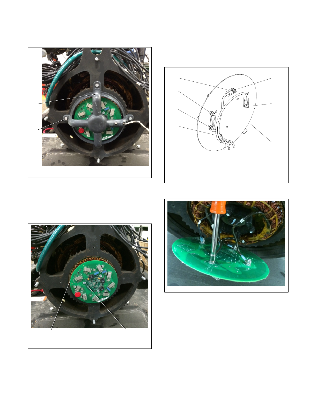
Use the FRX activator service kit when replacing the
FRX activator board on 20--200 kW generator sets that
are equipped with a Fast-ResponserX alternator.
Read the entire installation procedure and compare the
kit parts with the parts list at the end of this publication
before beginning installation. Perform the steps in the
order shown.
Safety Precautions
Observe the following safety precautions while
performing this procedure.
Accidental starting.
Can cause severe injury or death.
Disconnect the battery cables before
working on the generator set.
Remove the negative (--) lead first
when disconnecting the battery.
Reconnect the negative (--) lead last
when reconnecting the battery.
WARNING
Disabling the generator set. Accidental starting can
cause severe injury or death. Before working on the
generator set or equipment connected to the set, disable the
generator set as follows: (1) Move the generator set master
switch to the OFF position. (2) Disconnect the power to the
battery charger. (3) Remove the battery cables, negative (--)
lead first. Reconnect the negative (--) lead last when
reconnecting the battery. Follow these precautions to prevent
starting of the generator set by an automatic transfer switch,
remote start/stop switch, or engine start command from a
remote computer.
(Decision-Makerr3+ and 550 Controllers)
Disabling the generator set. Accidental starting can
cause severe injury or death. Before working on the
generator set or equipment connected to the set, disable the
generator set as follows: (1) Press the generator set off/reset
button to shut down the generator set. (2) Disconnect the
power to the battery charger, if equipped. (3) Remove the
battery cables, negative (--) lead first. Reconnect the negative
(--) lead last when reconnecting the battery. Follow these
precautions to prevent the starting of the generator set by the
remote start/stop switch.
(RDC, DC, RDC2, DC2, Decision-Makerr3000, 3500, and
6000 Controllers)
Procedure
Note: Read all safety precautions at the beginning of
this publication before performing any work on
the generator set.
1. Remove the generator set from service.
1.1 Press the generator set master control
OFF/RESET button or move the generator set
master switch to the OFF position.
1.2 Disconnect power to the battery charger, if
equipped.
1.3 Disconnect the generator set engine starting
battery, negative (--) lead first.
2. Access the alternator end of the
generator set.
2.1 Open the enclosure panels as needed.
2.2 Remove the junction box rear cover.
2.3 Remove the alternator (rodent) guard, if used.

2TT-1710 6/17
3. Remove the existing components.
3.1 Remove the 4 screws and the LED optic board
holder. See Figure 1.
SB-742
1. LED optic board holder
2. Screws (qty. 4)
1
2
Figure 1 Removing LED Optic Board Holder
3.2 Remove the 3 screws and the existing FRX
activator board from the exciter armature. See
Figure 2. The existing FRX activator board and
3 screws will not be reused.
SB-742
1. FRX activator board
2. Screws (qty. 3)
12
Figure 2 Removing the FRX Activator Board
3.3 Access the back of the FRX activator board and
disconnect the exciter armature leads (AC1, AC2,
and AC3) and rotor assembly leads (F1 and F2) by
removing the 5 elastic stop nuts. Note the lead
terminals and their positioning on the FRX
activator board silkscreen. See Figure 3 and
Figure 4.
GC70113B-
1. Exciter armature lead AC2
2. Exciter armature lead AC1
3. FRX activator board
4. Rotor assembly lead F1
5. Rotor assembly lead F2
6. Exciter armature lead AC3
7. Silkscreen positioning box
1
2
3
4
5
6
7
Figure 3 FRX Activator Board
SB-742
Figure 4 Removing Leads from the FRX Activator
Board

TT-1710 6/17 3
3.4 Remove the spacer by removing the 3 screws.
See Figure 5. The existing spacer and 3 screws
will not be reused. Remove the bow washer and
bolt only when changing the armature.
GC70113B-
1. Exciter armature
2. Bow washer (position washer with convex side outward)
3. Bolt
4. Three screws
5. Spacer
1
2
3
4
5
NOTE: Remove items 2 and 3 only when changing the armature.
Figure 5 Spacer Removal
4. Install the new components.
4.1 Mount the new spacer (GM98936) to the exciter
armature using 6 thread-forming Torx head
screws (M7500CE-05020-85). See Figure 6 and
Figure 11.
Note: Orient the non-electrical connection mounting
hole to the mounting hole above the keyway. See
Figure 8.
1
1. Thread-forming Torx head screws (M7500CE-05020-85 qty. 6)
Side View
Figure 6 Spacer (GM98936) Installation
4.2 Route the exciter armature and rotor leads (AC1,
AC2, AC3, F1, and F2) around the outer diameter
of the spacer to the inside to eliminate slack. See
Figure 7 and Figure 8.
Note: Lead connection locations are identified on the
spacer and in Figure 8.
Note: Secure excess lead length before attaching
terminals.
Figure 7 Routing of Leads
No electrical connection
AC1
AC2
AC3
F1
(F+)
F2
(F--)
1
2
1. Route leads around spacer OD to inside to eliminate
slack (leads not shown).
2. Terminals (X-283-58 qty. 5) and stainless steel hex nuts
(M934-04-SS).
Terminal barrels located down into spacer pockets.
Figure 8 Spacer (GM98936) Connections

4TT-1710 6/17
4.3 Use 5 terminals (X-283-58) and 5 stainless steel
hex nuts (M934-04-SS) to connect leads AC1,
AC2, AC3, F1 and F2 to the spacer studs. Torque to
1.3 Nm (12 in. lbs.). Locate the terminal barrels
down inside the spacer pockets. See Figure 8 and
Figure 11.
4.4 If the armature was changed, secure the new
exciter armature by reusing the existing bolt and
bow washer. See Figure 5. Torque to 194 Nm
(143 ft. lbs.).
4.5 Secure the activator board (GM98939-1) to the
studs on the spacer by using 5 stainless steel
elastic stop hex nuts (M985-04-SS) and a
thread-forming screw (X-6071-8). Torque to 1.3
Nm (12 in. lbs.). See Figure 9 and Figure 11.
1
2
1. Thread-forming screw (X-6071-8)
2. Stainless steel nuts (M985-04-SS qty. 5)
Figure 9 Activator Board
4.6 Replace and tighten the 4 screws attaching the
LED optic board holder to the end bracket and
torque to 6.2 Nm (4.6 ft. lbs). See Figure 10.
SB-742
1. LED optic board holder
2. Screws (qty. 4)
1
2
Figure 10 Replacing LED Optic Board Holder
4.7 Install the alternator (rodent) guard to the end
bracket (if equipped).
4.8 Replace the junction box panels.
4.9 Replace the enclosure panels (if equipped).
5. Restore the generator set to service.
5.1 Check that the generator set is OFF.
5.2 Reconnect the generator set engine starting
battery, the negative (--) lead last.
5.3 Reconnect power to the battery charger, if
equipped.
Parts List
Kit: GM101821-S
Qty. Description Part Number
1Spacer GM98936
6Screw, thread forming Torx head M7500CE-05020-85
5Terminal X-283-58
5Hex nuts, stainless steel M934-04-SS
5Nylock nuts, stainless steel M985-04-SS
1PCB activator board GM98939-1
1Screw, thread forming X-6071-8

TT-1710 6/17 5
5
GC79429-43
1. Spacer (GM98936)
2. Thread--forming Torx head screw (M7500CE-05020-85 qty. 6)
3. Terminal (X-283-58 qty. 5), not shown
4. Stainless steel hex nut (M934-04-SS qty. 5)
5. Activator board (GM98939-1)
6. Thread-forming screw (X-6071-8)
7. Stainless steel nylock nut (M985-04-SS qty. 5)
3
6
4
1
2
Listed in order of assembly:
Side View
7
Figure 11 Kit Components Shown in Order of Assembly

6TT-1710 6/17
Notes

TT-1710 6/17 7
Notes

8TT-1710 6/17
KOHLER CO., Kohler, Wisconsin 53044 USA
Phone 920-457-4441, Fax 920-459-1646
For the nearest sales and service outlet in the
US and Canada, phone 1-800-544-2444
KOHLERPower.com
Kohler Power Systems
Asia Pacific Headquarters
7 Jurong Pier Road
Singapore 619159
Phone (65) 6264-6422, Fax (65) 6264-6455
Availability is subject to change without notice. Kohler Co. reserves the
right to change the design or specifications without notice and without any
obligation or liability whatsoever. Contact your local Kohlerrgenerator
set distributor for availability.
2016 and 2017 by Kohler Co. All rights reserved.
Table of contents
Other Kohler Industrial Equipment manuals
Popular Industrial Equipment manuals by other brands

nord
nord B 1050 Operating and assembly instructions

Siemens
Siemens FLENDER B3 E Series Assembly and operating instructions

LMI
LMI Gocator 2490A-2-R-16-T user manual

Siemens
Siemens 8US1998-1CA10 operating instructions

GIGAIPC
GIGAIPC QBiX-Pro-WHLA8565H-A2 quick start guide

werma
werma StockSAVER instruction manual

DALIN
DALIN DLVC Installation, operation and maintenance

Nidec
Nidec LEROY-SOMER LSA 40 Installation and Maintenance

Belimo
Belimo FSAF24-SR US quick start guide

Bühler technologies
Bühler technologies GAS 222.10 manual

schmersal
schmersal AZM400Z-ST2-I2-2P2P-E manual

Carlos Silva
Carlos Silva CSG20 Operation manual