Kolmeks FC Series User manual

Subject to change without prior notice
1
\\W2s\users\minnara\käyttöhjeet\Kolmeks_FCkäyttöohje\Manual_FCpumps_en_20080506.indd
OPERATING INSTRUCTIONS
CENTRIFUGAL PUMPS WITH INTEGRATED FREQUENCY CONVERTER
FC_ -SERIES
AE_-,
L_-,
AL_-,
T- and
AT-
SARJAT

Subject to change without prior notice
2
\\W2s\users\minnara\käyttöhjeet\Kolmeks_FCkäyttöohje\Manual_FCpumps_en_20080506.indd
Content
1. General............................................................................................ 3
1.1 Symbols................................................................................................................................................ 3
1.2 Applications ........................................................................................................................................ 3
1.3 Manufacturer ...................................................................................................................................... 3
1.4 Version................................................................................................................................................. 3
2.1 Handling, transport and storage of the pump .................................................................................. 4
2. Handling, transport and storage of the pump ............................4
3. Design and function......................................................................4
3.1 Construction ........................................................................................................................................ 4
3.2 Technical data..................................................................................................................................... 4
3.3 Rating plate ....................................................................................................................................... 5
3.4 Pump identification ........................................................................................................................... 5
4. Safety ............................................................................................6
4.1 Safety instructions ............................................................................................................................. 6
4.3 Elements of danger if safety regulations are not obeyed............................................................... 6
4.4 Safety instructions for inspection and assembly............................................................................. 6
4.2 Training ............................................................................................................................................... 6
4.5 Operating the pump........................................................................................................................... 6
5. Installation, introduction and start-up ........................................6
5.1 General................................................................................................................................................. 6
5.2 Positions for installation ....................................................................................................................7
5.3 Electrical connections .........................................................................................................................7
5.4 Control methods and connections .................................................................................................... 8
5.4.1 I/O’s of the FC-pump (inputs and outputs).................................................................................... 8
5.4.2 Factory settings .............................................................................................................................. 8
5.4.3 FCA -pump - speed reference from potentiometer ...................................................................... 9
5.4.4 FCB -pump - constant pressure between the pump flanges ......................................................10
5.4.5 FCC -pump - constant pressure between inlet- and outlet-line...................................................11
5.4.6 FCCVAK -pump - constant pressure between supply- and return-line with
external controller in use (SETUP 1) ....................................................................................................... 12
5.4.7 FCCVAK -pump - constant pressure between supply- and return-line with
controller of the frequency converter in use (SETUP 2)........................................................................ 13
5.4.8 FCD -pump - constant pressure in discharge flange....................................................................14
5.4.9 FCE -pump - sensorless, pre-programmed pump curves ............................................................ 15
5.4.10 FCF -pump - constant temperature ............................................................................................ 16
5.4.11 FCF -pump - the speed according to temperature ...................................................................... 17
5.4.12 FCG -pump - controlled by external system ................................................................................18
5.4.13 Connections to the alarm receiving station.................................................................................19
5.4.14 Local control panel (optional)...................................................................................................... 20
6. Service, spare parts and troubleshooting.................................. 22
6.1 Shaft seals......................................................................................................................................... 22
6.2 Other parts ....................................................................................................................................... 22
6.3 Troubleshooting ............................................................................................................................... 23
7. Declaration of Conformity ........................................................... 27

Subject to change without prior notice
3
\\W2s\users\minnara\käyttöhjeet\Kolmeks_FCkäyttöohje\Manual_FCpumps_en_20080506.indd
1. General
Suitability of materials and seals for pumped liquid shall be always checked between pur-
chaser and supplier.
The nominal pressure and the max. temperature of pumped liquid are stamped on the pump
rating plate. Never use the pump in any other application or conditions without manufacturer’s
acceptance. In the case of damage there may be danger to persons by having poisoning, burns,
wounds etc. depending on the pumped liquid and it’s temperature and pressure. The pump
surface temperature may cause danger depending on the working conditions.
Clean, thin, non-aggressive liquids.
- circulating water in for heating and cooling systems
- water-glycol mixtures. Recommendation: propylene glycol
- nominal pressure 10 bar.
- like in L- and AL -series, but nominal pressure 16 bar.
Clean, thin, slightly aggressive liquids.
- domestic water, oxygen rich waters
- nominal pressure 10 bar.
Agressive, thin, not bigger solid particles containing liquids
- in addition to above mentioned liquids various acids, salts, oxidizing and chemically
active organic fluids
- nominal pressure 16 bar.
Temperature range: -10 ... + 95 °C (continuous + 80°C)
Max. temperature of environment +40°C (diurnal average max. +35°C)
AE-, L-, AL-,
T-, AT-
1.2 Applications
L-, ALH-
LS-, ALS-
AEP-, LP-,
ALP-
Pump series Applications
The most common applications are heating, air condition, cooling systems. Also heat exchangers, pressure boos-
ting systems, district heating systems, ice halls, public baths and industrial processies.
1.1 Symbols
Warns that failure to observe the precaution
may cause personal injury or damage to pro-
perty.
Warns that failure to observe the precau-
tion may cause electric shock
1.3 Manufacturer
Indicates something to be noted by the
reader.
This product is manufactured by OY KOLMEKS AB, P.O.BOX 27, FIN-14201 TURENKI, FINLAND.
1.4 Version
Release date of this manual is 04.01.2005. This is version no. 5.
All types of
FC-pumps

Subject to change without prior notice
4
\\W2s\users\minnara\käyttöhjeet\Kolmeks_FCkäyttöohje\Manual_FCpumps_en_20080506.indd
The pump and motor constitute a unit, where the rotating parts of both the pump and the motor are on the same
shaft (mono-block design). The motor is of a dry type and the frequency converter is integrated to the electric motor.
Electric motor: Totally enclosed, fan cooled A.C. motor, with frequency converter.
Protection form: IP54
Insulating class: F
3.1 Construction
3. Design and function
3.2 Technical data
Pump type Flanges Weight kg(* Max. input Nominal current Twin pump
power kW A (400 V)
AE_-25/4,-26/4FC_ G 1 15 0,27 0,53 -
AE_-25/2,-26/2FC_ G 1 20 0,85 1,5 -
AE-32/4, -33/4FC_ G 1 1/4 20 0,5 0,9 -
AE-32/2, -33/2FC_ G 1 1/4 20 1,5 2,6 -
L_-32A/4FC_ DN32 19 0,27 0,53 T-32A/4FC_
L_-32A/2FC_ DN32 25 0,85 1,5 T-32A/2FC_
L_-40A/4FC_ DN40 25 0,5 0,9 T-40A/4FC_
L_-40A/2FC_ DN40 29 1,5 2,6 T-40A/2FC_
L_-50A/4FC_ DN50 33 0,7 1,4 T-50A/4FC_
L_-50C/2FC_ DN50 49 2,5 4,5 T-50C/2FC_
L_-65A/4FC_ DN65 47 0,7 1,4 T-65A/4FC_
L_-65A/4FC_ DN65 56 1,6 2,6 T-65A/4FC_
L_-65A/4FC_ DN65 67 2,8 4,7 T-65A/4FC_
L_-65B/2FC_ DN65 69 4,3 6,9 T-65B/2FC_
L_-65B/2FC_ DN65 100 8,0 12,4 T-65B/2FC_
L_-80A/4FC_ DN80 48 0,7 1,4 T-80A/4FC_
L_-80A/4FC_ DN80 62 1,6 2,6 T-80A/4FC_
L_-80A/4FC_ DN80 76 3 4,9 T-80A/4FC_
L_-80A/2FC_ DN80 74 4,3 6,9 T-80A/2FC_
L_-80A/2FC_ DN80 105 8,0 12,4 T-80A/2FC_
AL_-1032/4FC_ DN32 25 0,5 0,9 T-40A/4FC_ (DN40)
AL_-1032/2FC_ DN32 29 1,5 2,6 T-40A/2FC_ (DN40)
AL_-1066/4FC_ DN65 47 0,7 1,4 T-65A/4FC_
AL_-1066/4FC_ DN65 56 1,6 2,6 T-65A/4FC_
AL_-1066/4FC_ DN65 67 2,8 4,7 T-65A/4FC_
AL_-1065/2FC_ DN65 69 4,3 6,9 T-65B/2FC_
AL_-1065/2FC_ DN65 100 8,0 12,4 T-65B/2FC_
AL_-1081/4FC_ DN80 62 1,6 2,6 T-80A/4FC_
AL_-1081/4FC_ DN80 76 3 4,9 T-80A/4FC_
AL_-1081/2FC_ DN80 74 4,3 6,9 T-80A/2FC_
AL_-1081/2FC_ DN80 105 8,0 12,4 T-80A/2FC_
AL_-1102/4FC_ DN100 70 1,6 2,6 AT-1102/4FC_
AL_-1102/4FC_ DN100 86 3,7 5,8 AT-1102/4FC_
AL_-1106/4FC_ DN100 170 4,4 7,2 AT-1129/4FC_
AL_-1106/4FC_ DN100 200 8,3 13,0 AT-1129/4FC_
AL_-1129/4FC_ DN125 175 4,4 7,2 AT-1129/4FC_
AL_-1129/4FC_ DN125 205 8,3 13,0 AT-1129/4FC_
Noise level of all pump types is under 70 dB (A, 1 m).
(* Single pump weight (AL). The weight of the twin pump (T/AT) is depending on the size of the motor and equipment
each unit. The weight of the twin pump is about two times the single pump weight.
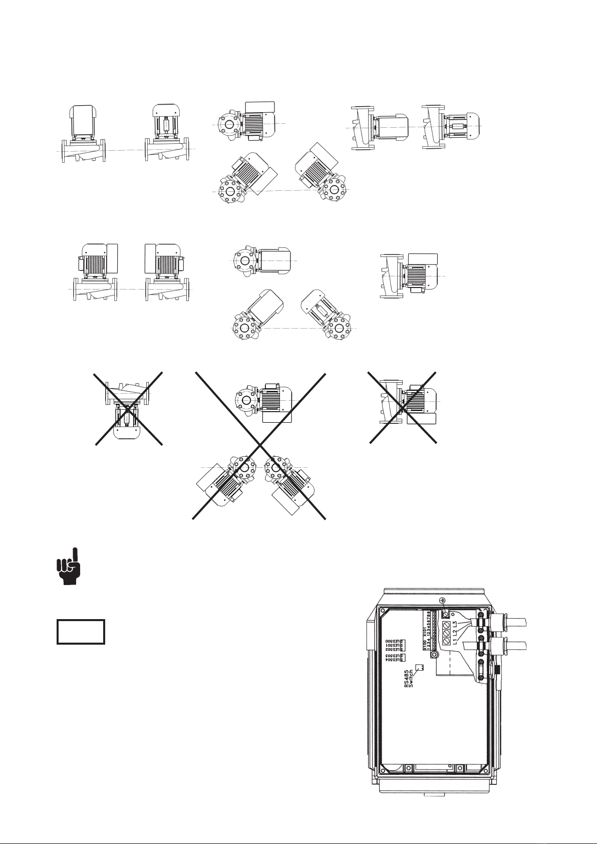
Normally the pumps are stable when they are transported and don’t go down even they are bent 10°. Pumps
shall be stored in a dry and cool place protected from dust. Temperature of environment must be in -10 °C ...
+50°C. It is not allowed to lift the pump from frequency converter. In the case of longer storage time or the
pump serves as a stand-by, it is recommended to rotate the pump manually f.ex. from the motor fan at least
once a month.
2. Handling, transport and storage of the pump
2.1 Handling, transport and storage of the pump

Subject to change without prior notice
5
\\W2s\users\minnara\käyttöhjeet\Kolmeks_FCkäyttöohje\Manual_FCpumps_en_20080506.indd
3.4 Pump identification
L P - 50 A / 4 FC C 10 45
L_= single in-line pump, with flanges
AL_= single in-line pump, with flanges
AT,T = twin in-line pump, with flanges
AE = single in-line pump, with pipe connection
no letter = grey cast iron EN-GJL-200 / 10 bar
H = nodular cast iron EN-GJS-400 / 16 bar
P = bronze CuPb5Sn5Zn5 / 10 bar
S = stainless steel AISI 316 / 16 bar
Material of pump housing, sealing flange
and impeller / nominal pressure of the
pump:
Pump series:
Flange sizes:
AE_:
25/26 = G 1
32 = G1 1/4
Version number (AL/AT) or letter (L_ /T)
Poles of the electric motor:
2 = rotation speed 50 r/s (50 Hz)
4 = rotation speed 25 r/s (50 Hz)
rotation speed 30 r/s (60 Hz)
FC = the frequency converter is integrated to
the motor
Control method:
A, B, C, D, E, F, G (please check 5.4 Control methods and connections)
The range of the pressure (dierence) transmit-
ter:
Examble:
10 = 0 - 1 bar
60 = 0 - 6 bar
Control range (depending on pump type):
Examble:
45 = 0,5 - 4,5 m
80 = 0,5 - 8 m
20 = 2 - 20 m
60 = 1 - 6 bar
5 - 30
LP-50A/4FCC1045 S6 K2 V1-C320001
10 135
540,45
OKFC-100 B2 F15
400 0,70
PM
123456/04
1,4
3.3 Rating plate
Shows the information about the electric motor and also design data of the pump.
L_/T:
40 = DN 40
50 = DN 50
65 = DN 65
80 = DN 80
100 = DN 100
125 = DN 125
AL_/AT:
x03 = DN 32
x05 = DN 50
x06 = DN 65
x08 = DN 80
x10 = DN 100
x12 = DN 125

Subject to change without prior notice
6
\\W2s\users\minnara\käyttöhjeet\Kolmeks_FCkäyttöohje\Manual_FCpumps_en_20080506.indd
4.2 Training
The persons who have responsibility for installing or/and operating the pump, should be trained.
4.3 Elements of danger if safety regulations are not obeyed
If the safety regulations are not obeyed, personal injuries or damage to the pump or related devices may occur. Vali-
dity safety instructions must be obeyed.
4.4 Safety instructions for inspection and assembly
it is user’s responsibility to ensure that persons who carry out inpections and installations are qualified experts and
familiarized themselves with these instructions carefully.
4.5 Operating the pump
Working safety of the delivered pump and related devices can be ensured only if these devices are operated according
to the section 1.2 Applications of this manual.
1. FC-pump must be disconnected from the mains if repair work is to be carried out. Check that the mains supply has
been disconnected and necessary time has passed (at least 4 minutes).
2. The device must be connected correctly to the earth. User must be protected from supply voltage and the pump
must be protected from short circuit according to the national and local requirements and standards. The overload
protection is included in FC -pump.
3. Earth leakage is more than 3,5 mA. It means, that installation of supply cable must be fixed.
4.1 Safety instructions
The position of the motor unit with the frequency converter can be changed by removing the motor unit from the
pump housing and setting it to the desired position (not in LH- and ALH-serie and in FCB, FCC ja -FCD-types with
certain limitations).
5. Installation, introduction and start-up
This manual includes important information concerning installation and operating the pump. Persons
who are involved in installation or/and operation of the pump, should read and understand these
instruction before installation or starting the pump.
4. Safety
There are live parts inside the frequency converter, when the supply voltage is connected. Incorrect
installation may cause damage to the pump or bodily injuries, even death. Touching the live parts may
be mortal even the supply voltage is disconnected. Wait at least 4 minutes! Obey instructions of this
manual and national and local requirements and standards.
- installation must be protected by fuses and insulated correctly.
- covers and cable inlet must be installed.
Attention:
It is user’s or certfied electrician’s responsibility to ensure the correct earthing and protection in accor-
dance with applicable national and local requirements and standards.
When installating the pump pay attention to the following:
- space enough for service and inspection of the pump
- free visibility to the scale of the potentiometer and curve plate of the pump.
- possibility to use lifting mechanism if needed
- shut-o valves on the both sides of the pump
- the frequency converter is not too close hot pipes.
5.1 General

Subject to change without prior notice
7
\\W2s\users\minnara\käyttöhjeet\Kolmeks_FCkäyttöohje\Manual_FCpumps_en_20080506.indd
5.2 Positions for installation
Allowed positions
Allowed positions, if the pipes of the pressure dierence transmitter are not installed to the flanges of the
pump
Not allowed positions
5.3 Electrical connections
All electrical work shall be carried out by qualified electrician approved by the local authorities.
Supply voltage may be connected with standard cable, screened cable is not required. Ensure,
that the nominal voltage of the electric motor corresponds the local supply voltage.
ATTN Use always screened control cables.
Before starting the pump fill and vent the system. Make
sure that the pump rotates freely by rotating it manually
f.ex. from the motor fan. Never start or let the pump run
dry.
Before starting the pump fill and vent the system. After
starting make sure that there is no extra noise coming
from the pump and that no leakages appear.

Subject to change without prior notice
8
\\W2s\users\minnara\käyttöhjeet\Kolmeks_FCkäyttöohje\Manual_FCpumps_en_20080506.indd
5.4 Control methods and connections
5.4.1 I/O’s of the FC-pump (inputs and outputs)
5.4.2 Factory settings
Terminal 1 / X101. No operation (setup1) or Feedback 4-20 mA (setup2) depending on selected control method.
Terminal 2 / X101. Speed reference 0-10V (setup1) or Reference of controller 0-10V (setup2) depending on selected
control method.
Terminal 3 / X101. Setup selection. Terminals 6-3 open/closed means setup1/setup2 selected. If setup1 is selected,
speed reference 0-10V is connected to the terminals 2-8 with potentiometer or external signal. The speed of the pump
is controlled according to the voltage signal. If the voltage is selected with potentiometer, the speed is constant.
When Setup2 is selected the controller of frequency converter is in use. The reference of controller 0-10V is connected
to the terminals 2-8 with potentiometer or external signal. Feedback signal 4-20 mA is connected to the terminal 1.
The speed of the pump changes according to the need of regulation.
Terminal 4 / X101. Stop / Start. Terminals 6-4 open means pump is not running, closed means pump is running.
Terminal 5 / X101. Reference freeze (both setup’s). When terminals 5 and 6 are connected, the speed reference (se-
tup 1) or the reference of the controller (setup 2) is freezed (not possible to change with potentiometer). By discon-
necting the wire between terminals 5 and 6, reference (0-10V) to the terminal 2 / X101 is in use.
Terminal 9 - (8) / X101. Digital output signal (24VDC, max. 25 mA) - fault. The voltage in termina indicast the fault
in the pump / inverter. Voltage is zero, if the supply voltage is not connected or there is no fault. If the potential free
contact is needed, the separate relay (24 VDC, < 25 mA) is needed. Please check the wiring diagram in section 5.4.
This terminal is possible to program with separate local control panel (not included is standard delivery) to an other
digital or analog output. E.g. 0 (4) - 20 mA analog output for frequency, reference, feedback, etc.
Relay output: Terminals 1, 2 and 3 / X102. Terminals 1 and 2 are connected when motor is running. Terminals 1 and 3
are connected when motor is not running (or the supply voltage is not connected).
Terminal 1 / X101 analog input 0-20 or 4-20 mA (dierent possible functions)
Terminal 2 / X101 analog input 0-10V or digital input (dierent possible functions)
Terminals 3, 4 and 5 / X101 digital input (dierent possible functions)
Terminal 6 / X101 24 V DC supply for digital inputs and feedback (max. 150 mA )
Terminal 7 / X101 10 V DC supply for potentiometer (max. 15 mA )
Terminal 8 / X101 0 V for terminals 1-7 ja 9
Terminal 9 / X101 analog or digital input (dierent possible functions,
Relay output:
Terminals 1, 2 and 3 / X102 relay output (dierent possible functions), potential free change-over
contacts, max. 250 V / 5 A

Subject to change without prior notice
9
\\W2s\users\minnara\käyttöhjeet\Kolmeks_FCkäyttöohje\Manual_FCpumps_en_20080506.indd
5.4.3 FCA -pump - speed reference from potentiometer
The speed of electric motor can be adjusted manually at the site.
Useful feature for commissioning of the pump. The pump will run
with constant speed. The reference can be freezed by connecting
wire between terminals 5 and 6.
Systems, where the duty point remains constant and where is no need for continuous automated regulation.
Applications
Pump, frequency converter and potentiometer.
Accessories
Operation principle
QH-curve of the pump is equal with that of single speed pump.
Pump curve
FACTORY DEFAULT: SETUP 1
SETUP 1 = speed reference (FCA)
SETUP 2 = controller of the frequency converter in use, e.g. FCB, FCC
Standard control connections
%
min.
30
50
70
90
max.
10
An example of curve plate of
FCA -pump.
m
l/s
The control range is shown in curve plate which is
located in cover of the frequency converter.
ATTN Mark the position of the potentiometer to the sticker
in cover of the frequency converter.

Subject to change without prior notice
10
\\W2s\users\minnara\käyttöhjeet\Kolmeks_FCkäyttöohje\Manual_FCpumps_en_20080506.indd
5.4.4 FCB -pump - constant pressure between the pump flanges
The level of the constant pressure dierence between the pump flanges can be adjusted by potentiometer. The set
value for the pressure dierence can be found from the curve plate of the pump. The pump will run with variable
speed. When adjusting the flow of the system, the main control valve must be opened as open as possible and then
the flow is adjusted by potentiometer. The reference can be freezed by connecting wire between terminals 5 and 6.
Systems, where are variations in the flow and where pressure losses are generated mainly on the consumption
equipment. Heating circulation, where the pressure loss on the heat exchanger is small.
Applications
Pump, frequency converter, potentiometer and dierential pressure transducer with pipes to the pump flange.
Accessories
Operation principle and flow adjustment
QH-curve of the pump is controlled to a horizontal line.
Pump curve
FACTORY DEFAULT: SETUP 2
SETUP 2 = constant pressure dierence (FCB, controller of
the frequency converter in use)
SETUP 1 = speed reference (FCA)
Standard control connections
%
min.
30
50
70
90
max.
10
By disconnecting the wire from potentio-
meter to the terminal 2 and connecting the
external 0-10V signal to the terminals 2-8,
the reference for pressure dierence is gi-
ven externally. Please check section 5.4.7.
m
l/s
An example of curve plate of FCB -pump.
The control range is shown in curve plate which is
located in cover of the frequency converter.
dierential pressure
transducer
ATTN Mark the position of the potentiometer to the sticker
in cover of the frequency converter.

Subject to change without prior notice
11
\\W2s\users\minnara\käyttöhjeet\Kolmeks_FCkäyttöohje\Manual_FCpumps_en_20080506.indd
The level of the constant pressure dierence between the inlet- and outlet-line of the system can be adjusted by
potentiometer. The set value for the pressure dierence can be found from the curve plate of the pump. The pump
will run with variable speed. When adjusting the flow of the system, the main control valve must be opened as open
as possible and then the flow is adjusted by potentiometer. The reference can be freezed by connecting wire between
terminals 5 and 6.
Systems, where are variations in the flow and where pressure losses are generated mainly on the source of heat
equipment. Heating and cooling circulations and the pressure boosting of parellel circulations.
Pump, frequency converter, potentiometer and dierential pressure transducer with pipes. One pipe to be installed to
the suction or pressure flange of the pump and the another one on to the system, inlet or outlet pipe.
Operation principle and flow adjustment
QH-curve of the pump is controlled to a quadratic. The relation of
pressure loss in the source of heat (cold) to the loss in the system de-
fines the shape of the curve.When the losses in the heat exchanger are
large part of the whole losses in the system the curve is more steep.
%
min.
30
50
70
90
max.
10
5.4.5 FCC -pump - constant pressure between inlet- and outlet-line
Applications
Accessories
Pump curve
l/s
m
FACTORY DEFAULT: SETUP 2
SETUP 2 = constant pressure dierence (FCC, controller of the frequency converter in use)
SETUP 1 = speed reference (FCA)
Standard control connections
By disconnecting the wire from potentio-
meter to the terminal 2 and connecting the
external 0-10V signal to the terminals 2-8,
the reference for dierential pressure is
given externally. Please check section 5.4.7.
An example of curve
plate of FCC -pump.
The control range is shown in curve
plate which is located in cover of the
frequency converter.
dierential pressure
transducer
ATTN Mark the position of the potentiometer to the sticker
in cover of the frequency converter.

Subject to change without prior notice
12
\\W2s\users\minnara\käyttöhjeet\Kolmeks_FCkäyttöohje\Manual_FCpumps_en_20080506.indd
5.4.6 FCCVAK -pump - constant pressure between supply- and return-line with external
controller in use (SETUP 1)
The level of the constant pressure dierence between the inlet- and outlet-line of the system can be adjusted by
external control system (speed reference 0-10 V to the terminal 2).
Operation principle (speed reference 0-10 V for pump)
Before adjusting and balancing the system the dierential pressure transducer is connected to the external control
system. The main control valve must be opened as open as possible and then the flow is adjusted by potentiometer,
which is connected to the terminal 2 (constant speed) to replace external speed reference while adjusting and balan-
cing the system. When the system has adjusted and balanced, the value of the pressure dierence is read and saved
to the control system as a reference value.
Flow adjustment and balansing the system
Alternatively the correct pressure dierence value can be adjusted with potentiometer when the pump is connected
as a standard FCC -pump (check the previous page). When the system has adjusted and balanced, the reference of
the pressure dierence (m) can be read from the scale of the potentiometer (e.g. 20 % = 1.7 m), which is then saved
as a reference value to the external control system.
The switch in external control system
between terminals 4-6 väliin (e.g. automatic
summer stoppage).
*) When pump is delivered from the factory,
the wire of the potentiometer is connected
to the terminal 2 then the pump can be
operated as FCA -pump. By disconnecting
the wire and connecting the external voltage
signal to the terminal 2, the pump is control-
led externally.
Check and update the connections!
In the cover of the frequency converter is
curve plate, where the set value for the
pressure dierence can be found in ratio
(%) to the range of the reference of the
pressure dierence and to the position of
the potentiometer. Curve plate is valid, when
setup2 is selected, terminal 6-3 is closed.
According to the factory default, the setup1
is selected, speed reference 0 V corresponds
the minimum speed and 10 V corresponds
maximum speed. The rotation speed unit is
r/s, which is marked in the rating plate.The
corresponding frequencies are minimum 10
Hz and maximum 50 or 60 Hz. The datas-
heet, where the pump curves can be read
with dierent frqeuncies, is also delivered
with this version.
FACTORY DEFAULT: SETUP 1
SETUP 1 = speed reference from external controller (FCCVAK1)
SETUP 2 = reference for dierential pressure from external control system
(controller of the frequency converter is in use, FCCVAK2)
Standard control connections
An example of curve plate of
FCCVAK -pump.
The control range is shown in curve
plate which is located in cover of
the frequency converter.
dierential pressure
transducer

Subject to change without prior notice
13
\\W2s\users\minnara\käyttöhjeet\Kolmeks_FCkäyttöohje\Manual_FCpumps_en_20080506.indd
5.4.7 FCCVAK -pump - constant pressure between supply- and return-line with controller of the
frequency converter in use (SETUP 2)
The level of the constant pressure dierence between the inlet- and outlet-line of the system can be adjusted by
external control system (reference for dierential pressure 0-10 V to the terminal 2). The operation and connections
are the same like in FCC -pump (section 5.4.5), except the reference for pressure dierence in given from the external
control system.
Operation principle (reference for pressure dierence 0-10 V for pump)
FACTORY DEFAULT: SETUP 2
SETUP 2 = reference for dierential pressure from external control system (control-
ler of the frequency converter is in use, FCCVAK2)
SETUP 1 = speed reference from external controller (FCCVAK1)
Standard control connections
The switch in external control system between terminals 4-6 (e.g. automatic summer stoppage).
*) When pump is delivered from the factory, the wire of the potentiometer is connected to the terminal 2 then the pump
can be operated as FCA -pump. By disconnecting the wire and connecting the external voltage signal to the terminal 2, the
pump is controlled externally.

Subject to change without prior notice
14
\\W2s\users\minnara\käyttöhjeet\Kolmeks_FCkäyttöohje\Manual_FCpumps_en_20080506.indd
The level of the constant pressure on the pressure flange of the pump or on the outlet-line of the system can be adju-
sted by potentiometer. The set value for the pressure dierence can be found from the curve plate of the pump. The
pump will run with variable speed. The reference can be freezed by connecting wire between terminals 5 and 6.
Pressure boosting or other open systems, where constant pressure is required.
Applications
Pump, frequency converter, potentiometer and pressure transmitter with pipes. The pressure transmitter is installed
to the pressure flange of the pump or near to the consumtion in the pipe line.
Accessories
Operation principle
%
min.
30
50
70
90
max.
10
5.4.8 FCD -pump - constant pressure in discharge flange
FACTORY DEFAULT: SETUP 2
SETUP 2 = constant outlet pressure (controller of the frequency converter is in use,
FCD)
SETUP 1 = speed reference from potentiometer (FCA)
Standard control connections
An example of curve plate of FCD
-pump.
The control range is shown in curve
plate which is located in cover of
the frequency converter.
*) Pressure switch for dry run protection
can be connected between terminals 6-4.
Pressure switch is not included in standard
delivery.
ATTN Mark the position of the potentiometer to the sticker
in cover of the frequency converter.

Subject to change without prior notice
15
\\W2s\users\minnara\käyttöhjeet\Kolmeks_FCkäyttöohje\Manual_FCpumps_en_20080506.indd
5.4.9 FCE -pump - sensorless, pre-programmed pump curves
Systems, where are variations in the flow. Heating and cooling circulations and the pressure boosting of parellel
circulations.
Pump, frequency converter and potentiometer.
Operation principle, pump curve and adjusting the flow
The pump curve is selected with potentiometer from the
curve plate. The selection is stepless. When adjusting
the flow of the system, the main control valve must be
opened as open as possible and then the flow is adjusted
by potentiometer.
Applications
Accessories
%
min.
30
50
70
90
max.
10
l/s
m
FACTORY DEFAULT: SETUP 2
SETUP 2 = variable pressure (FCE)
SETUP 1 = speed reference from potentiometer (FCA)
Standard control connections
ATTN Mark the position of the potentiometer to the sticker
in cover of the frequency converter.

Subject to change without prior notice
16
\\W2s\users\minnara\käyttöhjeet\Kolmeks_FCkäyttöohje\Manual_FCpumps_en_20080506.indd
The constant temperature, which is adjusted by potentiometer, is kept up by regulating the flow. The reference can
be freezed by connecting wire between terminals 5 and 6.
Applications
Accesories
Operation principle
Pump, frequency converter, potentiometer, temperature transmitter (and sensor).
Heating and cooling systems, where the constant temperature is required.
%
min.
30
50
70
90
max.
10
When ordering the pump, the response of the control must be informed. In the heating system the res-
ponse is normal, in the cooling system inverse.
5.4.10 FCF -pump - constant temperature
ATTN
FACTORY DEFAULT: SETUP 2
SETUP 2 = constant temperature (FCF1, controller of the frequency converter in use)
SETUP 1 = speed reference (FCA).
By disconnecting the jumper between terminals 3-6 (setup1), the pump is running at constant speed (FCA -pump).
Standard control connections
An example of curve plate of FCF
-pump.
The control range is shown in curve
plate which is located in cover of
the frequency converter.
Mark the position of the potentiometer to the sticker
in cover of the frequency converter.

Subject to change without prior notice
17
\\W2s\users\minnara\käyttöhjeet\Kolmeks_FCkäyttöohje\Manual_FCpumps_en_20080506.indd
Applications
Heating and cooling systems, where the flow is controlled by temperature.
5.4.11 FCF -pump - the speed according to temperature
The speed reference is given by temperature transmitter.
Accesories
Operation principle
Pump, frequency converter, potentiometer, temperature transmitter (and sensor).
When ordering the pump, the response of the control must be informed. In the heating system the res-
ponse is normal, in the cooling system inverse.
ATTN
FACTORY DEFAULT: SETUP 2
SETUP 1 = speed reference (FCA) constant temperature (FCF, controller of the frequency converter in use)
SETUP 2 = speed referense according to the temperature (FCF2)
By disconnecting the jumper between terminals 3-6 (setup1), the pump is running at constant speed (FCA -pump).
Standard control connections
Mark the position of the potentiometer to the sticker
in cover of the frequency converter.

Subject to change without prior notice
18
\\W2s\users\minnara\käyttöhjeet\Kolmeks_FCkäyttöohje\Manual_FCpumps_en_20080506.indd
The speed reference for pumps is given from external control system, external controller, process control, etc.
Pump, frequency converter, potentiometer (for FCA -connections).
Systems, where are variations in the flow and/or where the flow is controlled mainly with the pump. The pump is
controlled by external system or controller.
5.4.12 FCG -pump - controlled by external system
Applications
Accessories
Operation principle
FACTORY DEFAULT: SETUP 1
SETUP 1 = speed reference 0-10 V (FCA, from potentiometer or FCG from external controller)
SETUP 2 = controller of the frequency converter in use (e.g. FCB, FCC)
The switch in external control system between terminals 4-6 väliin (e.g. automatic summer stoppage). When pump is delivered from the factory,
the wire of the potentiometer is connected to the terminal 2 then the pump can be operated as FCA -pump
Standard control connections
*) When pump is delivered from the factory,
the wire of the potentiometer is connected
to the terminal 2 then the pump can be
operated as FCA -pump. By disconnecting
the wire and connecting the external voltage
signal to the terminal 2, the pump is control-
led externally.

Subject to change without prior notice
19
\\W2s\users\minnara\käyttöhjeet\Kolmeks_FCkäyttöohje\Manual_FCpumps_en_20080506.indd
5.4.13 Connections to the alarm receiving station

Subject to change without prior notice
20
\\W2s\users\minnara\käyttöhjeet\Kolmeks_FCkäyttöohje\Manual_FCpumps_en_20080506.indd
5.4.14 Local control panel (optional)
The FC_ -pump optionally features a Local Control Panel - LCP, which makes up the complete interface for operation
and monitoring of the FC_ -pump.
LCP installation
LCP is connected to the terminal X100, 1-4
LCP functions
The functions of the control panel can be divided into three groups:
- display
- keys for changing program parameters
- keys for local operation
All data are indicated by means of 4-line alpha-numeric display, which in normal operation is able to show 4 me-
asurements and 3 operation conditions continuously. During programming, all the information required for quick,
eective parameter setup of the FC_ -pump will be displayed. As a supplement to the display, there are three LEDs
for voltage, warning and alarm. All programming parameters of the FC_ -pump can be changed immediately from the
control panel, unless this function has been blocked vial parameter 018.
Reference, value of potentiometer
(or other value which is defined in
parameter 010))
Control panel is connected to these
terminals
Motor current or other value
which is defined in parameter
011
Feedback value or other
value which is defined
in parameter 012
Frequency or other va-
lue which is defined in
parameter 009. Active
warnings and alarms.
Active setup. Setup1 speed reference (A- or G-version ), Setup2
Reference control ( B,C,D)
With MENU button the parame-
ter mode is selected.
With OK button the changes
are confirmed. Sometimes the
change is confirmed without
pushing OK.
With CANCEL button you'll get
back without confirming the
changes, if OK is not pushed.
START button. FC-pump must be left
to RUNNING MODE before disconnecti-
on of control panel!!
With +/- buttons the large reading can be selected. 23 dierent
option eg. the feedback mA or reference V also motor power,
current, temperatures etc.
Parameters are selected with +/- button after pushing MENU
button and selection parameter group with narrow buttons.
After pushing CHANCE DATA button with +/- buttons is the new
value of the parameter selected
After pushing MENU
button, parameter group 0
… 9 are selected with these
narrow buttons or after
pushing CHANCE DATA but-
ton the required decimal is
selected with these narrow
buttons.
By pushing CHAN-
GE DATA button
the submenu of
paramater setup is
selected.
DISPLAY STATUS - chan-
ges the first line from
headline to analog values.
If button is hold, the titles
of the analog values are
shown: REF. , CURR. ,
FEEDB. eferense, motor
current and feedback)
Mode.
Normal:
REM RUN OK
This manual suits for next models
39
Table of contents
Other Kolmeks Water Pump manuals
Popular Water Pump manuals by other brands

Debem
Debem KM70 Installation, operating and maintenance manual

Grundfos
Grundfos AP80 Vortex Safety instructions

Flux
Flux F 550 S Series Original main operating instructions

KSB
KSB Compacta UZ10.450D Installation & operating manual

Idex
Idex Trebor PURUS CP Operation & maintenance manual

XPOtool
XPOtool 61962 Operation manual

Pentair
Pentair JUNG PUMPEN HIGHLOGO 2-00E instruction manual

Intex
Intex ECO 7231 owner's manual

Witt
Witt HRP Series quick start guide

Xylem
Xylem GOULDS LC Installation, operation and maintenance instructions

Surtek
Surtek BS510 User's Manual and Warrantly

Pentair
Pentair HYDROMATIC HPGB750 Installation and service manual