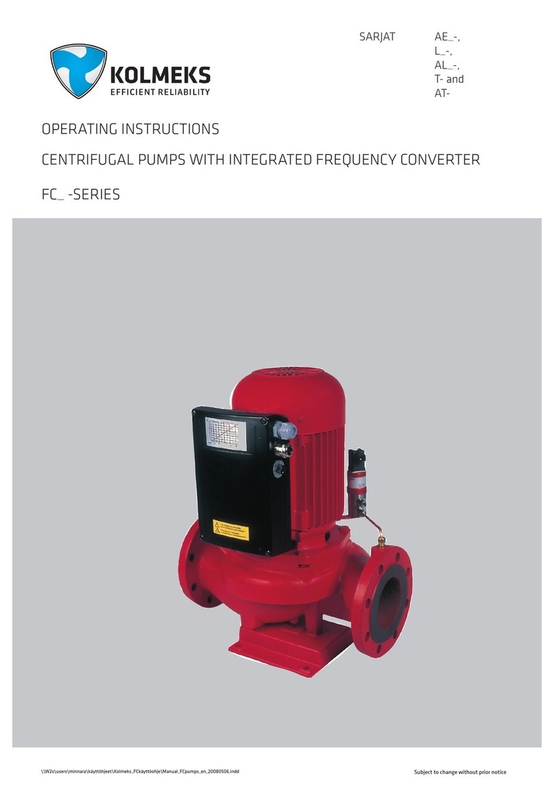
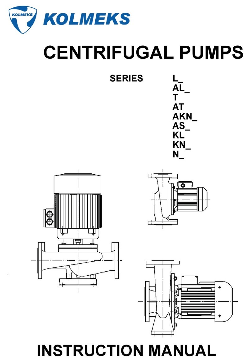
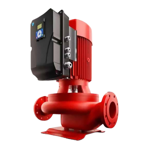
Kolmeks AE Series Manual

20.4.2021/Kolmeks manual EN rev 3.docx
Installation, Operation and Maintenance instructions
AE_, AKN_, AL_, AP, AT, K_,
L_, T
Inline centrifugal pumps

20.4.2021/Kolmeks manual EN rev 3.docx

20.4.2021/Kolmeks manual EN rev 3.docx
1 GENERAL
This product has safe and reliable operation in the function for which it is specified. A pump is a piece of equipment that has
pressurized parts and rotating parts which can be dangerous. Thus, fully follow all the safety measures in the instructions.
Personal injuries are possible if you do not follow the instructions.
The main heading Safety Instructions includes general health and safety instructions and also other safety information related to
this supply. Such information includes all important requirements of national legislation and other safety information given by the
plant operator.
The correct process and application data is important for the safe and reliable operation of the product. Environmental
circumstances must be specified to Kolmeks before the pump delivery.
Such conditions are for example:
- Unusual temperature
- High humidity
- Atmospheres that cause corrosion
- Pressure changes in the process
- Flow below the minimum permitted, dry running
- Explosive and/or fire hazard areas
- Dust, sandstorms
- Earthquakes
Special safety measures are also necessary when the liquid that goes through the pump is for example:
- Flammable
- Corrosive, abrasive
- Poisonous
- Crystallizing
- Solids-containing
- Gas-containing
You must follow the safety and operation instructions. If these are not followed, a risk to the personnel and the environment is
possible, for example:
- Failure of important functions of the pump and/or plant
- Failure of specified procedures of maintenance and repair
- Risk of electrical, mechanical and chemical hazards to the personnel
- Environmental risk because dangerous material is released
2. SAFETY OF MACHINERY
2.1 General
The supply does not include the design of the operation environment of the machine, the power circuits, control
circuits and controls of machine operation. However, the European Machinery Directive 2006/42/EC on the safety
of machines and/or related national legislation of the country where the machine is used are mandatory related to
the necessary health and safety requirements in the operation of the process.
It is necessary that the Customer has taken into account the necessary requirements that are shown in this
instruction when designing, purchasing and starting up the process control systems, other controls and equipment
related to the machine. Some of these requirements are also applicable to the personnel that operate the machine.
As far as the above is applicable, the Customer must also follow the appropriate legislation on electrical safety
(such as the low-voltage directive 2014/35/EU) or electromagnetic compatibility of equipment (EMC directive
2014/30/EU). During the operation of the machine you must also follow the appropriate occupational safety
legislation of the country where the machine is used.

20.4.2021/Kolmeks manual EN rev 3.docx
2.2 Necessary health and safety requirements
2.2.1 General remarks
2.2.1.1 Definitions
When necessary, the potential dangerous areas related to the machine and its operating environment, persons
working in the dangerous areas and all operator groups of the machine must be specified together by the Customer
and the Manufacturer. This may be necessary for example because of operation training arranged for the operators
of the machine.
2.2.1.2 Principles of safety integration
To ensure safety integration, as a machine manufacturer we follow the Machinery Directive and/or the national
legislation of the country where the machine is used as far as the supply is concerned. The installation, operation
and safety instructions supplied with the machine must be followed in the reception of the machine, in installation
and in operation. Before actual start-up, make sure that the machine, its controls and other equipment related to
the safe operation of the machine comply with the requirements given in the Machinery Directive and/or in national
safety legislation.
2.2.1.3 Materials and products
The products related to the use of the machine (such as liquids transferred in the process) must not endanger the
exposed persons' safety or health. The process where the machine is used must be designed so that the use of
liquids causes no hazard.
2.2.1.4 Lighting
Maintenance areas necessary for the regular inspections of the machine must have appropriate lighting.
2.2.1.5 Design of machinery to facilitate its handling
The environment of the machine must enable the moving of the machine or its components safely. If necessary,
the upper part of the machine can be attached to standard lifting equipment. You must fully follow the moving and
lifting instructions supplied with the machine.
2.2.2 Controls
2.2.2.1 Control and stopping devices
It must be possible to use the controls of the machine safely, and the controls must be designed in a manner that
will prevent a dangerous situation from occurring.
Follow the specified requirements related to controls, starting devices, stopping devices (including emergency stop
devices) and selection of control and operating modes for the machine and combinations of machinery. Refer to
the Machinery Directive and/or the national legislation of the country where the machine is used.
The controls of the machinery must be able to prevent fluctuations in energy supply or failures in the control circuit,
potentially causing dangerous situations. The interactive software used in the controls between the operator and
the machine must be easy to use.
2.2.3 Protection against mechanical hazards
2.2.3.1 Stability
You must follow fully the installation instructions supplied with the machine. This is to make sure that the machinery
is sufficiently stable.
2.2.3.2 Risk of damage during operation
The piping and hoses connected to the machine must be resistant to the internal and external forces. They must be
tightly attached and must withstand all loading and forces.
During operation, there is always a risk of damage to the piping connected to the machine (risk of high-
pressure/hot/harmful liquid spray) if the supplied instructions are not followed.

20.4.2021/Kolmeks manual EN rev 3.docx
2.2.3.3 Risks because of falling or ejecting objects
Follow the necessary precautions to prevent objects from falling or ejecting (e.g. tools used during installation).
2.2.3.4 Risks because of sharp edges or angles
Because of the functioning and design of the machine, its parts have sharp edges and/or angles. During installation
and maintenance, follow the instructions supplied with the machine and use the applicable personal protective
equipment.
2.2.3.5 Risks related to changes in the rotational speed
The instructions supplied with the machine show the usual rotational speed of the machine and its maximum
rotational speed limits. Follow these instructions when you select the rotational speed of the pump.
2.2.3.6 Risks related to moving parts
The installed guards used to prevent risks related to moving parts in the machine must be fully in position when the
machine is in operation. If guards are not included in the supply, make sure before start-up that the rotating parts
have protection. Also refer to the applicable legislation.
If rotating parts of the machine do not move freely during operation, stop the machine immediately. Find out the
cause of the failure. Refer to the instructions supplied with the machine.
2.2.4 Protection against other hazards
The electrical drives of the machine must have a design that prevents all electrical hazards. Follow the specified
rules and applicable legislation related to electrical equipment. The electrical equipment related to a machine that
complies with the Machinery Directive must follow the requirements shown in standard EN 60204-1:2006.
2.2.4.1 Static electricity
The build-up of potentially dangerous electrostatic charges in the machine and its auxiliary equipment must be
prevented or restricted.
2.2.4.2 Errors of fitting
Errors made when you install parts of the machine can be a source of risk. Because of this, follow fully the
instructions supplied with the machine during the installation and repairs of the machine.
Incorrect liquid and electrical connections can also be a source of risk. With liquid connections, follow the
instructions supplied with the machine. Incorrect electrical connections must not be possible or information on the
risk must be marked on cables and connectors.
2.2.4.3 Very high temperatures
If necessary, the machine must have warnings related to high surface temperatures. In these conditions, the risk of
injury caused by touching of the machinery parts must be decreased. Because of maintenance it is necessary to
heat of some parts before installation. Be careful during installation, and use applicable personal protective
equipment.
2.2.4.4 Fire and explosion
Correct and accurate information on the process and the functioning of the machine are necessary for the safe
operation of the machine. The special conditions at the point of operation must always be examined between the
Customer and Manufacturer when the machine is selected.
2.2.4.5 Noise and vibration
Noise level (dB [A] 1m) will be informed if needed. Follow the data given and do the necessary steps to prevent
risks caused by noise or vibration in the operating conditions.

20.4.2021/Kolmeks manual EN rev 3.docx
2.2.4.6 Radiation
The operators of the machine must fully follow the safety instructions related to the operation of this equipment.
2.2.4.7 Emissions
The instructions supplied with the machine give information on the control of leakages near the machine. If
necessary, perform the following measures to prevent dangerous emissions in the process:
- determine the amount of emissions and their potential effects (e.g. possibility of fire, applicable extinguishing
equipment)
- prevent the exposure of personnel to emissions
- keep the emissions under control and remove them in a controlled manner
- clean the area and machinery of emissions
- use applicable personal protective equipment and warnings
2.2.4.8 Slipping, stumbling and falling
When you install, service or repair the machine, follow the safety instructions applicable at the point of operation
and the instructions supplied with the machine and be sufficiently careful to prevent slipping, stumbling or falling.
2.2.5 Maintenance
2.2.5.1 Machinery maintenance
Follow the maintenance and repair instructions supplied with the machine. The instructions tell you when it is
necessary to stop and potentially drain the machine before maintenance. Wear applicable personal protective
equipment that is necessary for the maintenance task:
- hearing protectors
- eye protectors
- breathing protectors
- safety gloves, safety footwear, protective clothing
When you service or repair the machine, follow the principles of ergonomics (do not use too much muscular power,
use lifting equipment, lifting positions, lighting of the area, cleanliness etc.)
2.2.5.2 Access to operating position and servicing points
If the supply does not include location design for the machine, install the machine in a position that enables safe
maintenance and repairs of the machine.
When you design the operating environment make sure that there is sufficient maintenance space around the
machine.
2.2.5.3 Isolation from energy sources
The controls of the machine must include clearly identified devices that can be used to isolate the machine from all
energy sources. These devices must have locks if the re-connection of energy can be dangerous to persons. After
the energy supply is cut off, it must be possible to remove the energy stored in the process (e.g. release pressure)
without a health risk to persons.
2.2.5.4 Operator intervention
The controls of the machine must be designed so that the operator needs to intervene in the operation of the
machine as little as possible.
2.2.5.5 Cleaning of (internal) parts of machine
Refer to the instructions supplied with the machine and the safety instructions applicable at the point of operation to
do the potential cleaning of the machine safely.
2.2.6 Indications
2.2.6.1 Information and warning devices
Follow the specified requirements shown in the Machinery Directive and/or national legislation of the country where
the machine is used related to information and warning devices used in the machine.

20.4.2021/Kolmeks manual EN rev 3.docx
2.2.6.2 Warning of residual risks
Keep the safety warnings related to the machine clean in all conditions and replace the warnings if necessary. All
operators of the machine must know the residual risks related to electricity or the controls. Refer to specified
requirements shown in the Machinery Directive and/or national legislation of the country where the machine is
used.
2.2.6.3 Marks and instructions
Follow the Machinery Directive and/or national legislation of the country where the machine is used in terms of the
marks and instructions for the machine. Make sure that the marks and instructions for other equipment related to
the safe operation of this machine comply with legislation.
Make sure that the point of operation has instructions for emergencies, such as:
- how to give alarm
- location of rescue and fire extinguishing equipment
- availability of first aid supplies and equipment
3. NECESSARY SAFETY PRECAUTION
Before you service the product, the operators and maintenance personnel must know all necessary safety
precautions.
WARNING
Always stop the drive unit before you repair the pump.
* * *
Make sure that the drive unit cannot be started during repair.
WARNING
Use personal protective equipment when you you service the product.
WARNING
If it is possible that there is explosive gas or vapor inside the pump or piping, clean the
piping and pump with an efficient blower before you repair the pump.
* * *
If it is possible that there is explosive gas or vapor around the pump or in the servicing or
repair areas, ensure sufficient ventilation around the pump during the operation and
servicing of the pump.
WARNING
Do not expose the pump to heat when you disassemble the pump, because liquid trapped
in the pump can cause a risk of explosion.
WARNING
Tools used in an explosive air mixture must comply with the requirements of the relevant
standard.
* * *
In a potentially explosive environment, the pump must be lifted and transferred so that no
sparking can occur.
WARNING
Remove any potentially dangerous materials from the pump before the maintenance
procedures.

20.4.2021/Kolmeks manual EN rev 3.docx
WARNING
If there is a possibility of a dangerous return flow after the shutdown of the pump, install a
nonreturn device in the outlet piping.
WARNING
All safety devices (e.g. coupling guards) must be correctly installed before you start the
pump. Use guards with a non-sparking material for explosive areas.
WARNING
A leakage of a dangerous material can occur. Prepare the correct procedure for a safe
waste removal.
WARNING
The parts of the pump in contact with the liquid can be very hot. Do not touch them before
they are cool.
WARNING
The access of harmful bearing currents into the pump bearings must be prevented in
accordance with the instructions of the motor and frequency converter manufacturers.
CAUTION
Use the product only for the purpose for it is supplied. Refer to the correct operation
procedures described in these instructions.
CAUTION
Make sure that the product always has a shaft sealing system compatible with the pumped
liquid.
CAUTION
Verify the correct alignment of the coupling before you start the pump.
CAUTION
Do not start the pump before the system and the pump is filled up with the medium and
vented.
CAUTION
Do not operate the pump below the minimum recommended flow.
CAUTION
Make sure the suction valve is open during operation.

20.4.2021/Kolmeks manual EN rev 3.docx
4. OPERATING CONDITIONS THAT HAVE AN EFFECT ON PRODUCT SAFETY
The operation conditions shown in table 1 always have a direct effect on product safety. Therefore, try to avoid the
following problems related to the servicing or operating conditions of the product.
Table 1, Typical non-permissible operating conditions
Cause:
Consequence:
Discharge valve is closed.
Suction pressure has been estimated too low when pump was selected.
The pump is operated at too high a rotational speed.
Pressure increases
Discharge valve is closed.
Discharge valve is not open enough.
Incorrect estimate of properties of the pumped liquid when the pump was selected.
High temperatures
Failure of sealing water service
- Sealing water pump not started
- Sealing water valve not opened
- Sealing water equipment incorrectly adjusted
- Quality of the sealing water does not correspond to the requirements.
Incorrect estimate of inlet pressure when the pump was selected.
Pump is not correctly filled with the pumped liquid.
- Suction valve not opened
- Suction tank not properly filled
- Suction piping resistance or air tightness incorrectly examined
High temperatures (Sealing unit)

20.4.2021/Kolmeks manual EN rev 3.docx
5. TECHNICAL DATA
The individual pump technical data is found from the pump rating plate. The rating plate is stuck to the pump and to
the last page of this manual.
6. STRUCTURE
The pump with the integated motor is the set in which the impeller is mounted directly on the motor shaft. SD -
pump with the IEC motor is the set in which pump shaft is connected to the motor shaft with the coupling.
The pump impeller is installed directly onto the shaft of the electric motor (no separate couplings).
Fixed speed motor:
Asynchronous motor (IE3 0,75-160kW)
400/230 V, 50 Hz 0,03–3 kW
690/400 V, 50 Hz (3)4–160 kW
(Exception: L_-100S/4 3kW and AL_/AT-1129/4 3kW are equipped 690/400V motor)
Enclosure class:
IP 54
0,03–4 kW 4-poles motor: 1500 r/min 50Hz and 1800 r/min 60Hz
0,25–4 kW 2-poles motor: 3000 r/min 50Hz and 3600 r/min 60Hz
IP 55
5,5–190 kW 4-poles motor: 1500 r/min 50Hz and 1800 r/min 60Hz
5,5–54 kW 2-poles motor: 3000 r/min 50Hz and 3600 r/min 60Hz
Insulation class:
F
Duty type:
S1 (continuous duty)
Ambient temperature: max. +45 °C
IEC-standard electric
motor:
Asynchronous motor (IE2 or IE3) or Synchronous reluctance motor (IE4)
690/400 V, 50 Hz 4-90 kW
660/380 V, 60 Hz 4-90 kW
690/400 V, 60 Hz 4-90 kW
440 V, 60 Hz 4-105 kW
460 V, 60 Hz 4-110 kW
480 V, 60 Hz 4-110 kW
Note! In the data sheets, value of the nominal currents are indicated as approximate
values for
400 V, 50 Hz and 380-480 V, 60 Hz.
The exact values depend on the motor type, efficiency class and brand of motor.
That exact values are informed in the order confirmation and motors rating plate.
Enclosure class:
IP55
Insulation class:
F
Duty type:
S1 (continuous duty)
Ambient temperature: max. +40 °C

20.4.2021/Kolmeks manual EN rev 3.docx
7. SAFETY SYMBOLS
Sign of danger to persons Sign of voltage danger
Sign of danger to safe operation of the pump and/or protection of the pump itself
8. FIELDS AND LIMITS OF APPLICATION AND USE
Clean, thin, non-aggressive liquids
AE, AKN, AL,
AT, L, T
- circulating water for heating and cooling
- water-glycol mixtures, recommendation:
propylenglycol max. 40 %
Nominal pressure
10 bar
Max. temperature
+ 120°C (+ 100°C with plastic impeller)
Clean, thin, non-aggressive liquids
AKNH, ALH,
LH
- for higher temperature liquids
Nominal pressure
16 bar
Max. temperature
+ 120°C normal
+ 150°C with special seal
+ 180°C with quench and special seal
Aggressive, thin, not bigger solid particles
containing liquids
ALM
- in addition to above mentioned liquids various
acids, salts, oxidizing and chemically active
organic fluids
- sea water
Nominal pressure
16 bar
Max. temperature
+ 120 - 180°C depending on seal
construction/materials used
Clean, thin, slightly aggressive liquids
AEP, ALP,
LP, AP
- domestic water, oxygen rich waters
- sea water
Nominal pressure
10 bar
Max. temperature
+ 120°C (+ 100°C with plastic impeller)
Aggressive, thin, not bigger solid particles
containing liquids
ALS, LS
- in addition to above mentioned liquids various
acids, salts, oxidizing and chemically active
organic fluids
Nominal pressure
16 bar
Max. temperature
+ 120 - 180°C depending on seal
construction/materials used
Aggressive, thin, not bigger solid particles
containing liquids
ALX, LX
- in addition to above mentioned liquids various
acids, salts, oxidizing and chemically active
organic fluids
- sea water
Nominal pressure
16 bar
Max. temperature
+ 120 - 180°C depending on seal
construction/materials used
ATTN

20.4.2021/Kolmeks manual EN rev 3.docx
Suitability of materials and seals for pumped liquid shall be always checked between purchaser
and supplier.
9. SAFETY PRECAUTIONS: HANDLING, TRANSPORT AND STORAGE OF THE PUMPS
You can find the total gross and net weights of the supply in the packing list attached to the product or packing.
WARNING
Observe all instructions regarding lifting and transport to prevent crashing of the box or
assembly.
Make especially sure that these items are stable:
- Pump
- Spare parts.
Always ascertain the center of gravity of these items before you lift or transfer the pump.
Use personal protective equipment such as helmet, safety shoes and gloves.
If the proper lifting equipment is not available, transfer heavy assemblies with for example skids on the ground
level.
Lifting accessories must have the identification of the manufacturer, material and the maximum working load.
Lifting ropes used directly for lifting or holding the pump or pump unit must not include splicing other than at their
ends. Textile ropes and slings must not include knots, connections or splicing other than at the ends of the sling.
This is not applicable to an endless sling.
Clean, thin, non-aggressive liquids
- heating and cooling circulating systems
KD
- water-glycol mixtures, recommendation:
propylenglycol max. 40 %
Nominal pressure
10 bar
Max. temperature
+110°C
K, KM
Aggressive, low viscosity, not big solid particles
containing liquids
- in addition to above mentioned liquids various
acids, salts, oxidizing and chemically active
organic fluids
Nominal pressure
10 bar
Max. temperature
+110°C
ATTN

20.4.2021/Kolmeks manual EN rev 3.docx
Make sure that the lifting accessories can always sufficiently suspend the lifted assembly.
There must be a sufficient quantity of lifting ropes. Adjust them correctly to prevent damage to the product when
you lift it. A lifting chain must not touch the product during lifting (if it does, the painted and machined surfaces can
be damaged).
VARNING
Make sure that accepted and undamaged ropes and lifting accessories are available. The
lifting capacity of the lifting accessories and ropes must correspond to the weight of the
items you are lifting.
VARNING
In a potentially explosive environment, the pump must be lifted and transferred so that no
sparking can occur.
The heavier pumps are provided with lifting links.
Pumps shall be stored in a dry and cool place protected from dust.
In the case of longer storage time it is recommended to rotate the pump manually
f.ex. from the motor fan at least once a month. When the pump serves as a stand-by
or is stopped for longer time for some reason, it is necessary to start it for a while
after two weeks stoppage.

20.4.2021/Kolmeks manual EN rev 3.docx
10. INSTALLATION AND START-UP
10.1 Installation
When installing the pump pay attention to the following:
- space enough for service and inspection of the pump
- possibility to use lifting mechanism if needed
- shut-off valves on the both sides of the pump
The smaller pumps (below 15 kW) can be mounted without the foot.
The heavier pumps should be fastened to a foundation of concrete which is
isolated from the floor f.ex. with 20 mm thick gum or cork plate(s). The weight of
the concrete foundation must be about 1.5 times the weight of the pump.
The position of the motor unit and the terminal box can be changed by removing
the motor unit from the pump housing and setting it to the desired position (not in
AKN_ H, AL_ H L_ H external flushing).
10.2 Electrical wiring
All electrical work shall be carried out by an electrician approved
by the power supplier.
Check, that the voltage on the pump data plate corresponds to the mains voltage.
Standard connections:
Smaller motors (<4 kW) Bigger motors (≥(3)4 kW)
The motor must always be equipped with an overload protection or with a frequency drive, which has
been set according to maximum current Imax and the selected connection. The motor power supply
must be designed in accordance with Imax current and the local regulations and conditions.
Check the direction of rotation of the pump during start-up and always after re-connection. The flow direction is
indicated by an arrow on the pump housing or on fan cover
Never start or let the pump run dry. Before starting the pump fill and vent the system. Make sure that
the pump rotates freely by rotating it manually f.ex. from the motor fan.
After starting make sure that there is no extra noise coming from the pump and that no leakages appear.
An inventer can be used for regulating the speed of rotation of the pump. An inverter must be
adjusted to prevent the overload of the motor. The current switch-off is to be adjusted according to
rated current. Note. The use of over 50 Hz frequency may cause the overload of the motor. The
motor suitability for frequency drive use must be ensured if the supply voltage is more than 500V.
ATTN
ATTN
ATTN

20.4.2021/Kolmeks manual EN rev 3.docx
11. MAINTENANCE AND REPAIR
The pump doesn’t need any regular servicing.
As a shaft seal is used an adjustment free mechanical seal. It is a wearing part which has to be replaced if it starts
to leak. Note that few drops leakage per hour can be quite normal especially when coolants (f.ex. glycol) are
pumped.
11.1 Single mechanical shaft seal; type constructions
1 Rotating ring
2 Stationary ring
3 Body/bellows
4 Spring
5 O-ring
6 Backing plate
(not always)
The motor is equipped with ball bearings which are lubricated for life and therefore do not need any service. In the
case of any motor malfunction it is recommended to replace the whole exchange unit.

20.4.2021/Kolmeks manual EN rev 3.docx
11.2 Rating plate
When ordering spare parts, please specify the pump type, serial number, duty point, the size of impeller, the motor
type and power.
11.2.1 Pump with integrated motor
11.2.2. Pump with IEC-standard motor
Pump type Manufacturing year and month
Serial number Impeller diameter and material
Duty point Nominal power of motor
11.2.3. Example of rating plate for IEC-standard motor
Motor type
Rating
P = Single phase motor
T = External shaft seal
KT = Double shaft seal
Ln = Motor thermal protectors
En = Other difference (e.g. EXE)
Material:
P = Bronze’
H = Nodular Cast Iron
S = Stainless steel
Accessories:
X = Pump without baseplate
N = Seal kit no.7
H = Recirculation
Sn = Non-standard shaft seal
Kn = Non-standard surface treatment
Vn = Special voltage
Motor code
Pressure class and impeller diameter
Minimum efficiency index (MEI)
Enclosure and insulation class | Efficiency class of electric motor
Continuous duty
Nominal power and rotation speed
Pump type
Serial number
Duty point and max temperature of liquid
Motor type
Nominal voltages, currents and
max currents
Bearing types

20.4.2021/Kolmeks manual EN rev 3.docx
12. PARTS FOR PUMP
12.1 Pump with integrated motor (flanged connections)
POS.NO. DESCRIPTION
1 ELECTRICAL MOTOR 2 PUMP HOUSING
3 IMPELLER 5 SEALING FLANGE
8 BASE PLATE (not always) 16 COVER (T- and AT-serie)
24 SCREW OR NUT 25 WASHER
26 KEY 40 SHAFT SEAL
50 O-RING 55 O-RING (T- and AT-serie)
60 SCREW OR NUT 65 SCREW (T- and AT-serie)
67 SCREW 80 PIPE UNION (Internal flushing)
81 PIPE UNION (Internal flushing) 86 COOLING PIPE (Internal flushing)
93 FLAP (T- and AT-serie) 94 CYLINDICAL PIN (T- and AT-serie)

20.4.2021/Kolmeks manual EN rev 3.docx
12.2 Pump with integrated motor (thread connections)
POS.NO. DESCRIPTION
1 ELECTRICAL MOTOR
2 PUMP HOUSING
3 IMPELLER
5 SEALING FLANGE
24 NUT
25 WASHER (not always)
26 KEY
40 SHAFT SEAL
43 V-RING
50 O-RING
60 SCREW
80 PIPE UNION 2 piece
12.3 End-suction (KD, K, KM)
POS.NO. DESCRIPTION
1 ELECTRICAL MOTOR
2 PUMP HOUSING
3 IMPELLER
5 SEALING FLANGE
24 SCREW
25 WASHER
26 KEY
40 SHAFT SEAL
50 O-RING
60 SCREW OR NUT

20.4.2021/Kolmeks manual EN rev 3.docx
12.4 SD-pump with IEC-standard motor (flanged connections)
POS.NO DESCRIPTION
1 ELECTRICAL MOTOR
2 PUMP HOUSING
3 IMPELLER
5 SEALING FLANGE
6 MOTOR BRACKET (ADAPTER)
8 BASE PLATE
14 COUPLING
21 FLANGE-SHAFT
22 SCREW
24 SCREW
25 WASHER
26 KEY
40 MECHANICAL SHAFT SEAL
50 O-RING OR GASKET
60 SCREW / NUT
62 SCREW
67 SCREW
70 SCREW / NUT
73 SCREW
80 PIPE UNION (Internal flushing)
81 PIPE UNION (Internal flushing)
86 PIPE (Internal flushing)
89 WASHER
92 COUPLING PROTECTION
.

20.4.2021/Kolmeks manual EN rev 3.docx
13. REPLACING EXCHANGE UNIT
13.1. Less than 1,5kW
Note! Only an authorized person may carry out the replacement.
Starting situation. The pump is running normally.
1) Stop the pump, open any
possible safety switch and
remove fuses. Ensure that
no one is able to switch the
current on, even by
accident, during the
replacement. Close the
valves.
2) Detach the motor cable.
Open the screws/nuts of the
operating unit.
3) Lift the operation unit
from the pump housing.
Watch out for hot water!
4) Replace the gasket/O-ring
of the housing.
5) Install a new exchange
unit. Tighten the
screws/nuts of the unit
evenly.
6) Connect the motor cable
and open the valves. Start the
pump and check the direction
of rotation. Vent the system.
Monitor the operation of the
pump.
13.2 Over 1,5kW
Note! Only an authorized person may carry out the replacement.
Starting situation: The pump is running normally.
1) Stop the pump, open a
possible safety switch
and remove fuses.
Ensure that no one is
able to switch the current
on, even by accident,
during the replacement.
Close the valves.
2) Close the valves and detach
the connecting cable of the
motor. Next, detach the flush pipe
(in AKN_ H, AL_ H and L_ H -
pumps). Open the screws/nuts of
the operation unit.
3) Lift the exchange unit
by means of a hoist.
Watch out for hot water!
4) Replace the gasket/O-ring of
the housing.
5) Install a new
exchange unit. Tighten
the screws/nuts of the
unit evenly.
6) Connect the motor cable and
open the valves. Start the pump
and check the direction of
rotation. Vent the system. Monitor
the operation of the pump.
This manual suits for next models
29
Table of contents
Other Kolmeks Water Pump manuals
Popular Water Pump manuals by other brands

Grundfos
Grundfos MAGNA1 D instructions

Grundfos
Grundfos NK B ILLUSTRATED SERVICE INSTRUCTIONS

Ingersoll-Rand
Ingersoll-Rand ARO PD10P Series Operator's manual

Grundfos
Grundfos DME 60-940 l/h Safety instructions and other important information

Hedy
Hedy HealFusion user manual

Alemlube
Alemlube O30060 instruction manual

Xtreme Power
Xtreme Power 75132 Owner's manual and safety instructions

Drummond
Drummond 57718 Owner's manual & safety instructions

PFT
PFT BOLERO 400V operating manual

Flotec
Flotec Floodmate 7000 owner's manual

ProMinent
ProMinent Dulco Flex DF2a operating instructions

Cole Parmer
Cole Parmer VPS-200 Series instruction manual