1. Unpack your machine
The package comes with the FT201 pedal, a 9VDC, 500mA,
center-negative power supply and this manual. Make sure
that the power supply is rated for the line voltage of your
country: 120 VAC for the USA, 220 VAC for Europe or most oth-
er countries.
2. Connect it
Be sure your amp or mixer is turned off, then connect your in-
strument to the FT201 by using the AUDIO INPUT on the upper
right of the patch bay. Connect one of the three filter outputs
to your amp or mixer.
3. Set up the FT201 to a basic patch
Set all the rotary controls on the FT201 to 0. Turn down the
volume of your amplifier.
4. Power up / Bypass
Connect the FT201 power supply to the FT201 DC input on the
backside of the pedal. When you press the bypass switch the
EFFECT ON/OFF led will light up, this means the effect is ON.
5. Set levels
Make sure the EFFECT ON/OFF indicator is OFF. Play your in-
strument and adjust the volume. Press the Bypass switch
and the EFFECT ON/OFF indicator will turn green which means
the effect is now active. If necessary, adjust the INPUT GAIN
control to match the levels of the processed signal and the
bypassed signal.
6. Play
Now play that machine! Be aware of volume changes in your
signal when using the FT201. Make sure that when you plug
in the unit the RESONANCE slider control is not fully set to
HIGH, this to avoid very loud and very high pitched sounds
while sound checking (or you might just be really into that, in
that case, leave it up high and roll with it).
Dear KOMA user,
Filters are amongst the most important audio sculpting tools
when it comes to defining your own unique sound. There’s a
lot of discussion going on about different filter topologies,
their respective sound and how to electronically solve these
different approaches. At KOMA Elektronik, we went for a very
versatile filter architecture called state variable filter. One of
the advantages of this filter is that you have band pass, high
pass and lowpass characteristics available simultaneously
for a given input. Other musically convenient advantages are
the independently adjustable Q (resonance) and gain that
can be set without affecting other variables.
There are two gain cells in the signal path of a voltage-con-
trolled state variable filter so there are different approaches
to represent those gain cells. Usually these gain cells are
represented by an IC called ‘transconductance amplifier’
(a small chip) but for the FT201 we decided to take another
electronic part here commonly known as ‘vactrols’.
What is a vactrol? Basically it’s a light dependent resistor
(LDR) and a LED kissing each other under a lightproof plastic
blanket. When you send current through the LED, it shines
brighter, therefore the resistance of the LDR decreases and
vice versa. Vactrols are great for sound application because
they are not prone to distortion and are known for their soft
and organic, analog response and sound.
Sequencers, on the other side, are great tools for modu-
lation, possibly the most logical thing after a simple knob.
With the onboard step-sequencer you can twiddle with
charming frequencies and their resonant overtones or find
a pretty pattern to go through your tone. With the sequencer
output on the patch bay you can control other features of
the pedal as well as other KOMA Elektronik pedals or synthe-
sizers that accept control voltage.
Combining these two sound tools brings up a whole new va-
riety of defining your sound and playfully work with it. Have
fun with your new machine!
All the best from Berlin,
The KOMA Elektronik Team
FT 201
ANALOG FILTER/
10 STEP SEQUENCER
_
USER MANUAL
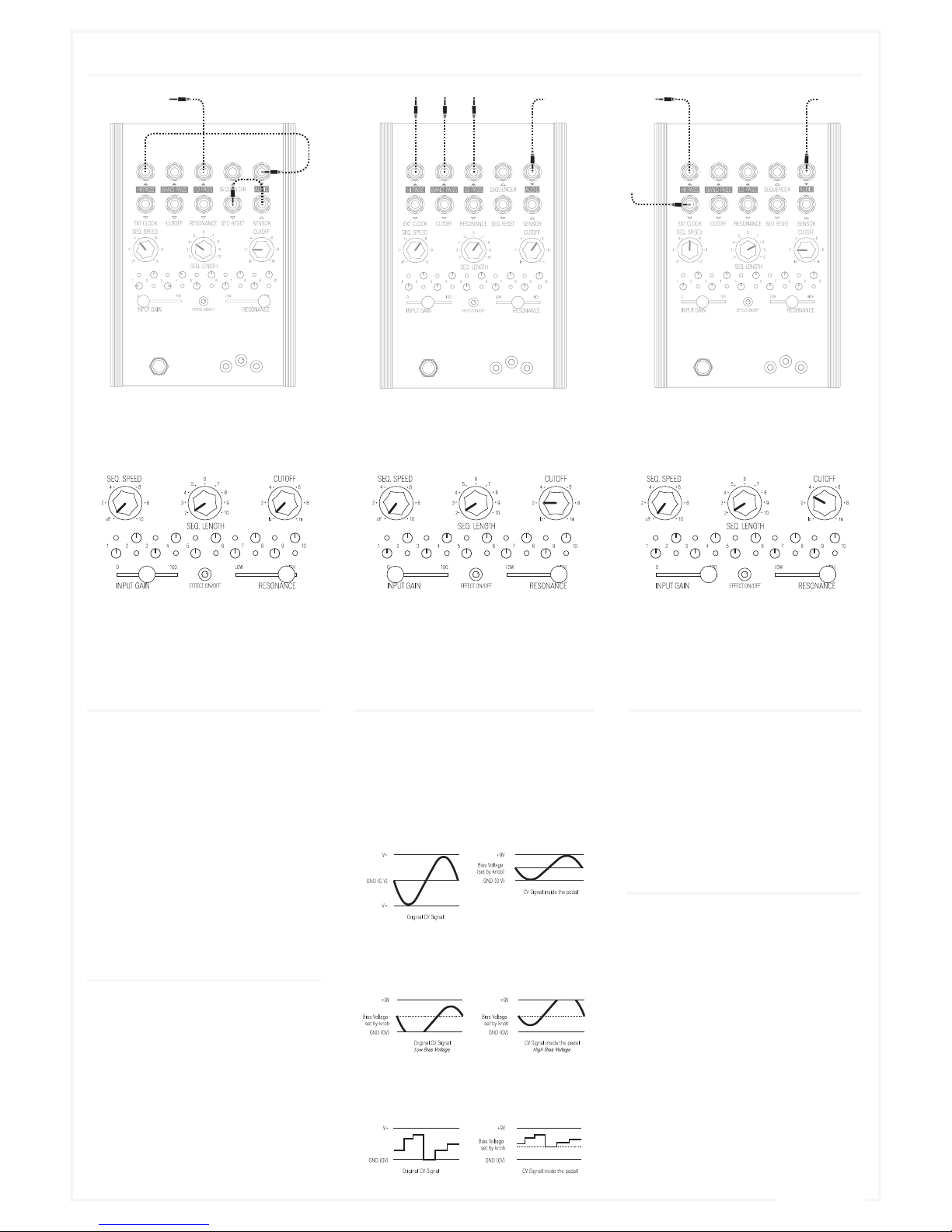
The FT201 is running on a +9V power supply. To make the unit compatible to all other equipment out there, we provide you with a trimmer for each CV input on the backside of the panel. So whenever you
notice a significant distortion or clipping in your control signal waveform or strange CV behavior simply turn the trim pot counter-clockwise until you hear the desired result. By turning it counter-clockwise
you attenuate the incoming CV signal. Fully counter-clockwise means that the incoming CV signal is completely trimmed down, whereas fully clockwise means that the incoming CV signal is arriving to the
circuit unattenuated.
Wouter Jaspers Christian Zollner
Robert Kunz Hayden Moskowitz
Imprint
KOMA Elektronik GmbH
is a subsidiary company of KOMA Elektronik B.V.
Managing Director:
Christian Zollner & Wouter Jaspers
Registered Office: Berlin, Germany
Court of Registration:
Amtgericht Berlin-Charlottenburg
Registernummer : HRB 145453
VAT ID: DE285522050
KOMA Elektronik GmbH
Mahlower Strasse 24
12049 Berlin-Neukölln
Germany
Front Panel Connections & Controls
Getting Started
Rear Panel Controls
Sensor CV Out
Adjust the sensitivity of the
motion controller.
Resonance CV In
Attenuates the incoming CV
signal.
Cutoff CV In
Attenuates the incoming CV
signal.
Sensor CV Out
Attenuates the outgoing CV signal
of the Sequencer.
DC Power Connector:
Use only KOMA
PSU to ensure
high quality
performance.
(Audio Output) BAND PASS 1
The bandpass output of the filter.
(CV Input) CUTOFF 2
Controls the cutoff frequency
of the filter. When you insert a
control voltage into this input
the CUTOFF knob determines the
offset voltage.
(Audio Output) HI PASS 3
The highpass output of the filter.
(CV Input) EXT. CLOCK 4
Accepts clock signals for the se-
quencer by overriding the inter-
nal clock set by the SPEED knob.
It reacts to rising edge triggers,
proceeding one step whenever a
trigger or gate signal arrives.
(CV Input) RESONANCE 5
Controls the amount of resonance
in your given filter setting. When
you insert a control voltage into
this input the RESONANCE slider
determines the offset voltage.
Sequencer Steps A
The sequencer of the FT201 con-
sists out of 10 steps that you set
with the 10 small knobs in the
middle of the unit. It is easy to
imagine these ten knobs as du-
plicates of the big CUTOFF knob,
the amount set with the little se-
quencer knob of the active step is
added to the current setting of the
CUTOFF knob, or in other words:
You can shift the sequencer CV up
and down with the CUTOFF knob,
similar to setting a bias voltage
for incoming CV signals. You can
use the sequencer CV Output on
the patchbay to controls another
function on the FT201 with CV or
send it to another device.
InpuT GaiN B
The INPUT GAIN slider of the FT201
provides you with an adjustable
gain to boost low level input sig-
nals. By sliding from left to right
you can boost your signal from
zero gain to 100 gain (0 to +20dB).
Footswitch C
Heavy duty Alpha foot switch
turning the effect on and off.
(Audio Output) LO PASS 6
The lowpass output of the filter.
7 SEQUENCER OUT (CV Output)
The output of the sequencer, ranging
from 0 – 7V. Note that this is the sum
of the sequencer itself and the the
CUTOFF knob.
Seq. Length D
The SEQ. LENGTH knob is a rotary switch that
lets you choose the length of the sequencer
pattern from 2 – 10; in other words, on what
step that the sequencer will go back to step
1. The currently active step is indicated by a
small red LED next to the step number.
ESensor
Emits a CV signal that can be connected to
any CV input on KOMA products or for ex-
ample your (modular) synthesizer or other
effect unit. By moving your hand over the
sensor you can control the parameters of
the CV input patchedto it.
8 SEQ. RESET (CV Input)
A rising edge trigger or gate sig-
nal arriving at this CV input resets
the sequencer to step 1. A trigger
will reset, and a gate will hold the
sequencer at step 1 as long as it
is high.
9 AUDIO IN (Audio Input)
The main audio input of the FT201.
The sound source plugged in here
will go through the whole effects
section.
10 SENSOR (CVOutput)
This is the CV output of the
infrared motion sensor. The closer
you move something towards the
sensor, the higher the CV raises.
You can set the sensitivity of the
sensor with a small trimmer on the
back called ‘Sensor’. The sensor
output is 0 – 8V.
H SEQUENCER speed
The SEQ. SPEED knob sets the
speed of the sequencer: the time
it takes to go from one step to the
next one and at the same time
also the duration of each single
step (On the scale that means: 2
is the fastest, 10 is the slowest). If
you turn the SEQ. SPEED knob fully
counter-clockwise you can turn
the sequencer off with a ‘click’
(there’s a built-in switch in the
potentiometer).
G Cutoff
Sets the cutoff frequency for the
filter, simultaneously for all three
filter characteristics. Fully counter-
clockwisesets the cutoff frequency
to the lowest and fully clockwise to
the highest frequency.
Fresonance
Sets the Q of the filter, better
known as resonance. The reso-
nance of a filter determines the
gain increase of the signal at the
cutoff frequency. Set it to LOW
(left) to leave the signal gain at
cutoff frequency at zero and slide
it to HIGH (right) to hear plenty of
resonance at the given cutoff fre-
quency. Be aware of the fact that
the filter might start self-oscillat-
ing when you are at or near maxi-
mum resonance.
The patch bay consists of ten 1/4” mono jack sockets used to send and receive various audio or control voltage signals. Blank arrows mark CV inputs/outputs, black arrows mark audio inputs/outputs.
If the arrow is pointing towards the jack socket it shows you that this is an output. If the arrow is pointing away from the jack socket it is an input.
The FT201 has been designed to accept unipolar CV signals only. Because the pedal runs on 9 V, every time you patch a control voltage to one of the CV inputs, the respective knob (e.g. SPEED knob or SPEED
IN (CV input) determines the offset voltage of your CV input signal.