6
2.1 Getting Started
The FX is a great device to apply effects on various instruments and
signals and works great with any of your electronic instruments, syn-
thesizers and (Eurorack) modular systems.
To get started, you will first need to bring the Field Kit FX to life. Grab
the included 9V PSU and plug the PSU into the DC connector on the
back side of the Field Kit FX.
For the Eurorack version, carefully connect your Field Kit FX to the
bus board of your Eurorack system with a ribbon cable, making sure
-12V aligns with the red stripe and eventually mount the module on
the rails of the case (for more detailed information with photos, skip to
the ‘Field Kit FX In A Eurorack System’ chapter).
2. User Manual
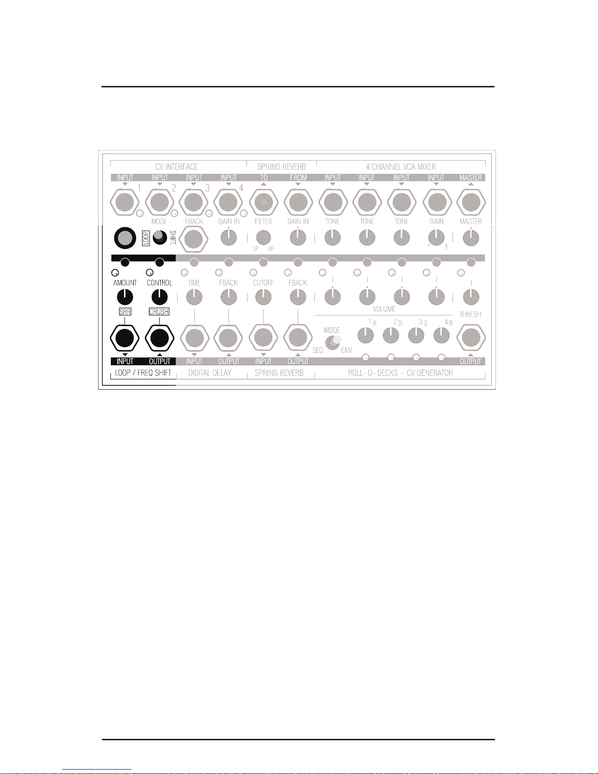
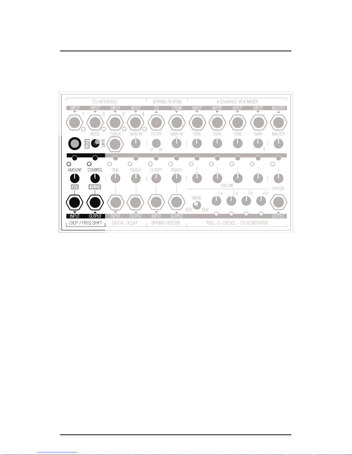
2.2 Function Overview
The Field Kit FX is an effect box which allows you to use several
effects at the same time including reverb, delay, an envelope genera-
tor, frequency shifter, looper, a bitcrusher, a sample rate reducer and
even a 4-step sequencer – all in one device! Its compact size makes
the FX ideal for touring and traveling, but the device is as useful in
the studio where you can explore its potential and experiment apply-
ing effects on various sounds, from acoustic instruments to synthesiz-
ers.
The Field Kit FX consists of seven different effect blocks of which
many parameters can be controlled with the CV Interface and its nifty
CV matrix.
All outputs are mono, except for the master output, which is dual
mono (“fake stereo”). If you have a Field Kit, you can connect the
two devices so they can instantly become friends! Use this manual
to check all the specifications on your device and get inspired by the
many possibilities the Field Kit FX has to offer!