Komfovent 392-12 User manual

Spiskåpa 392–12
Cooker hood 392–12
Garų surinktuvas 392–12
SSVV BBrruukkssaannvviissnniinngg
Säkerhetsföreskrifter ..................... 3
Installation ...................................... 4
Injustering av luftflöden .................. 7
Användning ..................................... 8
Service och garanti ......................... 9
GGBB UUsseerr iinnssttrruuccttiioonnss
Safety Instructions ....................... 1
Installation .................................... 11
Adjusting air flow .......................... 14
Instructions for use ...................... 15
Service and warranty .................... 16
LLTT NNaauuddoojjiimmoo iinnssttrruukkcciijjaa
Saugos taisyklės ........................... 17
Įrengimas ..................................... 18
Oro srauto reguliavimas ............... 21
Naudojimas .................................. 22
Priežiūra ir garantija ..................... 23

991. 485.5 3/126239/2 17- 1-19 (23 11)
SÄKERHETSFÖRESKR FTER
Läs noga igenom denna bruks-
och monteringsanvisning, i synner-
het säkerhetsföreskrifterna, innan
du installerar och börjar använda
produkten.
Spara bruksanvisningen för senare
användning eller till den som even-
tuellt övertar produkten efter dig.
Gör produkten strömlös innan all
form av rengöring och skötsel.
§Avledning av utblåsningsluften
skall utföras i enlighet med fö-
reskrifter utfärdade av berörd
myndighet.
§Utblåsningsluften får inte ledas
in i rökkanal som används för
avledning av rökgaser från t ex
gas- eller braskaminer, ved- el-
ler oljepannor etc.
§Avståndet mellan spis och pro-
dukt måste vara minst 45 cm.
Vid gasspis ökas avståndet till
65 cm. Om högre monterings-
höjd rekommenderas av gas-
spisens tillverkare ska hänsyn
tas till detta.
§För att undvika att fara uppstår
ska fast installation, utbyte av
sladdställ eller annan typ av
anslutning utföras av behörig
fackman.
§Att flambera under produkten
är inte tillåtet.
§Tillräckligt med luft måste till-
föras rummet när produkten
används samtidigt med pro-
dukter som använder annan
energi än el-energi, t ex gas-
spis, gas- eller braskaminer,
ved- eller oljepannor etc.
§ Produkten kan användas av
barn från 8 år och personer
med nedsatt mental, sensorisk
eller fysisk förmåga, eller brist
på erfarenhet och kunskap, om
de informeras om hur produk-
ten är avsedd att användas.
§Barn skall inte leka med pro-
dukten. Rengöring och under-
håll av produkten skall inte
utföras av barn utan tillsyn.
§Åtkomliga delar av produkten
kan bli heta i samband med
matlagning.
§Risken för brandspridning ökar
om inte rengöring sker så ofta
som anges.
991. 485.5 3/126239/2 17- 1-19 3

NSTALLAT ON
Spiskåpan är avsedd för montering infälld i
skåp. Spiskåpan är försedd med motordri-
vet spjäll, LED-belysning och metalltrådsfil-
ter. Installation, skötsel, underhåll mm
framgår av denna anvisning.
TEKNISKA U GIFTER
Fig. 1
Mått se Fig. 1
Elektrisk
anslutning
23 V ~ med
skyddsjord.
Belysning LED 2 x 2 W
Max anslutningsef-
fekt för styrledare 9 W vid 23 V~
TILLBEHÖR
Trumsats för anslutning till imkanal.
INSTALLATION
Monteringsdetaljer, skruvar för uppfästning
mm levereras med spiskåpan.
Elektrisk installation
Anslutningen skall göras fast och spiskåpan
måste föregås av en allpolig brytare. Instal-
lationen skall utföras av behörig fackman.
Fig. 2
Byte av spjällucka
Om spiskåpan ska monteras i kök där det
finns separat grundflödesventilation ska
den förses med tätslutande spjällucka. Byt
spjällucka innan spiskåpan monteras, se se-
parat anvisning.
Montering anslutningsstos med spjäll
Fig. 3
Utluftdonet levereras inuti spiskåpan.
Spjällaxeln A placeras i öglan under spjäl-
locket, se Fig. 3. Se till att klackarna B ham-
nar under plåtkanten och att donet snäpper
fast.
4991. 485.5 3/126239/2 17- 1-19

Montering av spiskåpan
Montering mellan, eller i skåp utan
botten.
Fig. 4
Spiskåpan monteras med hjälp av konsoler.
Märk ut och fäst skruvar, så att de sticker
ut några millimeter i båda skåpsidorna en-
ligt måttbilden, Fig. 4A. Om man vill placera
spiskåpans undersida i linje med skåpra-
dens undersida används det övre måttet,
1 2, se Fig. 4A. Konsolerna är justerbara
på spiskåpan för att passa olika skåpdjup,
Fig. 4B.
Fig. 5
Montera konsolerna i spiskåpan utan att
dra åt skruvarna helt och justera konsoler-
na så att de passar mot skåpsidorna, Fig.
5A. Häng upp spiskåpan i de förmonterade
skruvarna i skåpsidan. Dra åt skruvarna på
konsolen och i väggen, Fig. 5B. Lås fast
konsolerna med låsskruvar, Fig. 5C.
Montering i skåp med botten
Fig. 6
Fig. 7
Spiskåpan monteras med hjälp av konsoler.
Såga upp ett hål i skåpbotten enligt måttbil-
den, Fig. 6. Fäst konsolerna så långt in det
går på spiskåpan. Skjut upp spiskåpan i hå-
let mot skåpets botten. Drag ut, Fig. 7A,
och skruva fast konsolerna i sidorna på skå-
pet, Fig. 7B. Drag fast konsolerna i
spiskåpan.
Anslutning till frånluftkanal
Anslut spiskåpan med rör eller slang Ø125
mm.
Fig. 8
Obs!
Vid montering med anslutningsslang,
måste slangen monteras sträckt när-
mast anslutningen, Fig. 8.
991. 485.5 3/126239/2 17- 1-19 5

Justering av utdragbar front.
Fig. 9
Drag ut fronten helt. Lossa skruven för
frontstoppen, på undersidan av spiskåpan
och dra den så långt fram mot fronten det
går, Fig. 9.
Fig. 10
Skjut in fronten tills den hamnar i rätt läge
mot skåpraden, Fig. 1 . Drag ut fronten
igen och dra fast skruven för frontstoppen.
Byte av front.
Fig. 11
Fronten är löstagbar för byte mot annan
frontlist. Lossa skruvarna enligt Fig. 11.
6991. 485.5 3/126239/2 17- 1-19

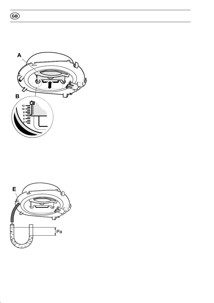
NJUSTER NG AV LUFTFLÖDEN
S JÄLLINSTÄLLNING
Grundflöde
Fig. 12
Grundventilationen ställs in genom att
skjutspjället A placeras i önskat läge enligt
markering B, Fig. 12. (Se diagram, sidan
24.)
Tryckfallsmätning
Fig. 13
Tryckfallsmätningen utföres genom att
slangen monteras på mätuttaget E i stosens
framkant, Fig. 13.
991. 485.5 3/126239/2 17- 1-19 7
ANVÄNDN NG
FUNKTION REGLAGE
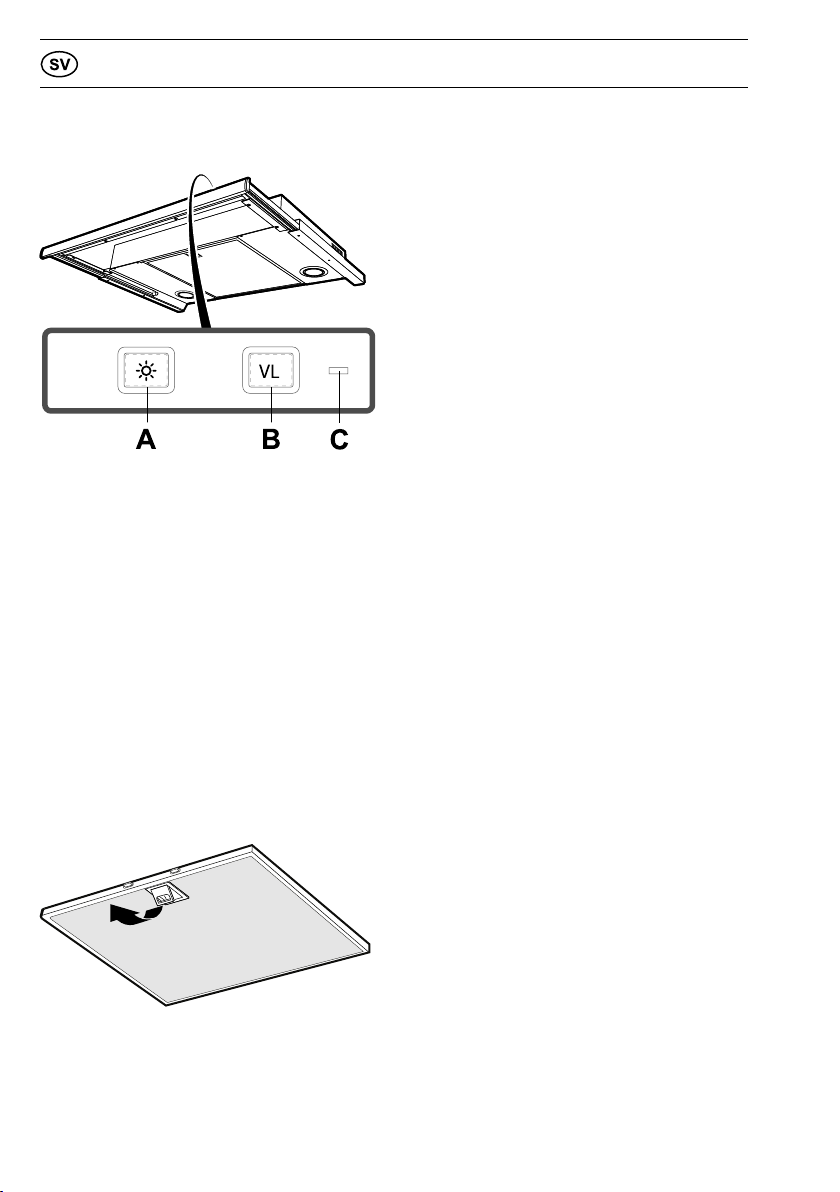
Fig. 14
A. Belysning
B. Spjällfunktion
C. Indikeringslampa (tänd vid öppet spjäll).
Vid matlagning öppnas spjället. Spjället
stängs automatiskt efter 6 minuter eller
genom att trycka en andra gång på knap-
pen B. Låt gärna spjället vara öppet en
stund före och efter matlagning, för att
hindra att os sprids i rummet.
SKÖTSEL OCH UNDERHÅLL
Rengöring
Spiskåpan torkas av med våt trasa och
diskmedel. Filtret ska rengöras 2 gånger
per månad vid normal användning.
Fig. 15
Ta bort fettfilter genom att öppna snäppet,
Fig. 15. Hantera filter försiktigt, var noga
med att inte bocka dem.
Blötlägg filtret i varmt vatten blandat med
diskmedel. Filtret kan även diskas i maskin.
Sätt tillbaka fettfilter efter rengöring, se till
att de snäpper fast ordentligt.
Insidan av spiskåpan samt spjället ska ren-
göras minst två gånger per år. Torka av
med våt trasa och diskmedel. Spjället ren-
görs enklast när det är öppet.
8991. 485.5 3/126239/2 17- 1-19

SERV CE OCH GARANT
Kontrollera att säkringen är hel. Prova alla
funktioner för att säkerställa vad som inte
fungerar.
Kontakta Komfovent
Du hittar företagets kontaktuppgifter på
www.komfovent.se
De kan hjälpa till att åtgärda felet eller anvi-
sa till närmaste servicefirma för snabb och
bra service.
Produkten omfattas av gällande EHL-
bestämmelser
EMBALLAGE- OCH
RODUKTÅTERVINNING
Emballaget ska lämnas in på närmaste
miljöstation för återvinning.
Symbolen anger att produkten
inte får hanteras som hushålls-
avfall. Den skall i stället lämnas
in på uppsamlingsplats för
återvinning av el- och elektro-
nikkomponenter. Genom att säkerställa att
produkten hanteras på rätt sätt bidrar du till
att förebygga eventuellt negativa miljö- och
hälsoeffekter som kan uppstå om produk-
ten kasseras som vanligt avfall. För ytterli-
gare upplysningar om återvinning bör du
kontakta lokala myndigheter, sophämt-
ningstjänst eller affären där du köpte varan.
991. 485.5 3/126239/2 17- 1-19 9
SAFETY NSTRUCT ONS
Carefully read these instructions
of use and the installation guide,
in particular the safety instruc-
tions, before you install and begin
using the product.
Save these instructions for later
use or for the party who may take
over the product after you.
Make sure you unplug the product
prior to any form of cleaning or
care.
§Diversion of exhaust air shall
be carried out in accordance
with instructions issued by the
appropriate authority.
§Exhaust air may not be direc-
ted into flues that are used for
fumes from, for example, gas,
wood or oil-burning stoves, fi-
replaces, etc.
§The distance between the coo-
ker and the product must be at
least 45 cm. For gas cookers,
the distance should be increa-
sed to 65 cm. If a higher
mounting height is recommen-
ded by the gas cooker manu-
facturer, this should be taken
into account.
§In order to avoid a potential
hazard, installation, replace-
ment of cables or other types
of connection should be car-
ried out by a qualified
professional.
§Flambéing underneath the pro-
duct is not allowed.
§There must be sufficient air in
the room when the hood is to
be used at the same time as
products that use energy sour-
ces other than electricity, i.e.,
gas hobs, gas, wood or oil-bur-
ning stoves or fireplaces, etc.
§ The product may be used by
children from 8 years of age
and persons with mental, sen-
sory or physical impairment, or
a lack of experience and know-
ledge, if they are informed on
how the product is to be used.
§Children should not be allowed
to play with the product. Clea-
ning and maintenance of the
product must not be perfor-
med by children without
supervision.
§Accessible parts of the product
may become hot in conjunc-
tion with cooking.
§The risk of a fire spreading in-
creases if cleaning is not car-
ried out as often as is
recommended.
1 991. 485.5 3/126239/2 17- 1-19
NSTALLAT ON
The cooker hood is intended for installation
built into cupboards. The cooker hood is
equipped with a motorised damper, LED
lamps and metal mesh filter. Installation,
care, maintenance etc., are described in
these instructions.
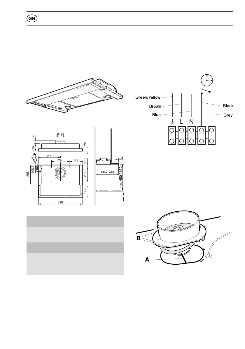
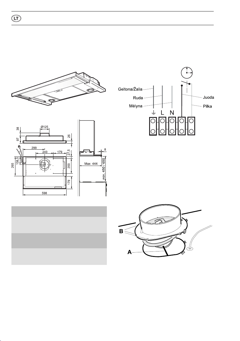
TECHNICAL INFORMATION
Fig. 1
Measurements see Fig. 1
Electrical
installation 23 V ~ earthed.
Lighting LED 2 x 2 W
Max. connection
output for control
cable
9 W at 23 V~
O TIONS
Drum attachment for connection to kitchen
flue.
INSTALLATION
Fixing parts, screws for mounting, etc. are
supplied with the cooker hood.
Electrical installation
The connection must be secured and the
cooker hood must be preceded by an omni-
polar switch. Installation must be carried
out by a qualified professional.
Fig. 2
Replacement of damper hatch
If the cooker hood is to be installed in kit-
chen with separate basic flow ventilation, it
must be fitted with tight-fitting damper. Rep-
lace the damper hatch before installing the
cooker hood, see separate instructions.
Installing the damper.
Fig. 3
A duct connector with damper is provided
inside the hood.
Position the damper axle "A" in the loop un-
der the damper lid; see Fig. 3. Ensure that
the clips "B" engage under the edge of the
plate. Press the connector into position un-
til the snap locks is fixed.
991. 485.5 3/126239/2 17- 1-19 11
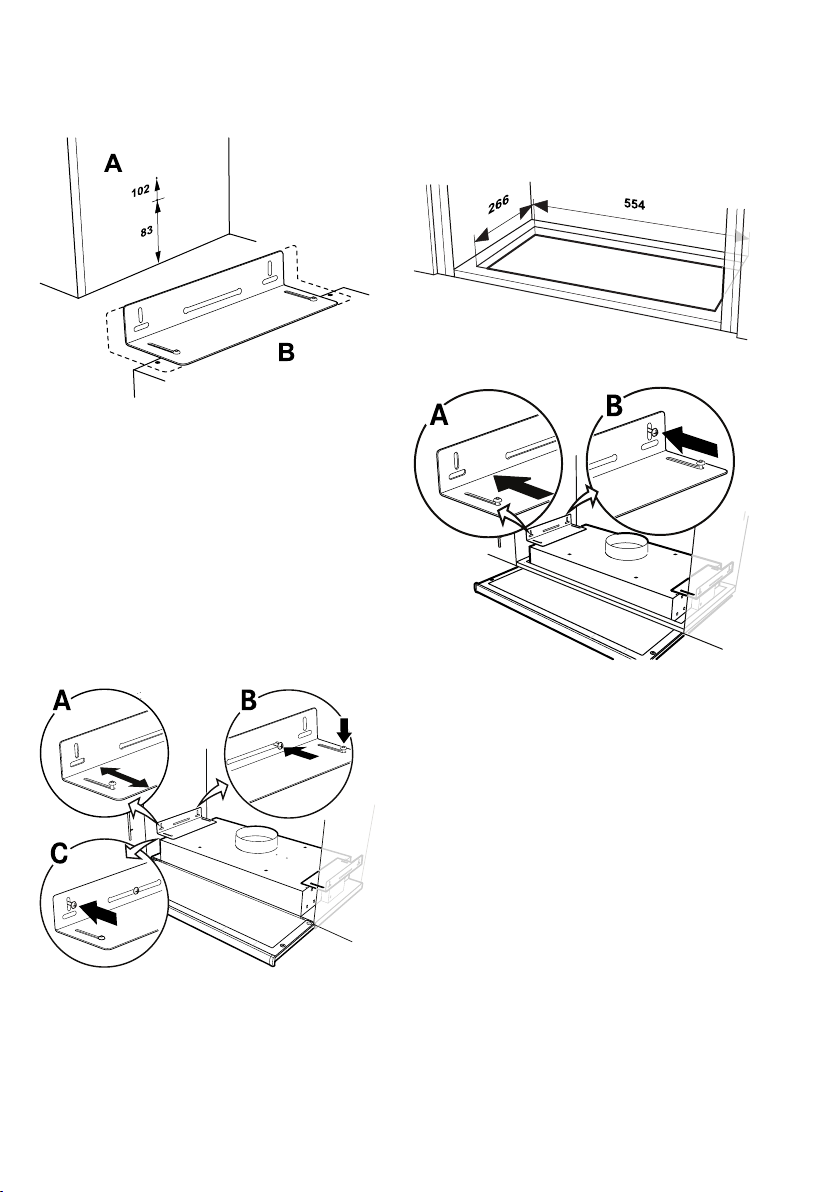
Installing the cooker hood
nstallation between or in cupboards
without bases.
Fig. 4
The cooker hood is installed using
brackets.
Mark out and fasten screws so that they
protrude a few millimetres from both cup-
board sides as illustrated, Fig. 4A. If it is in-
tended to align the underside of the cooker
hood with the underside of the row of cup-
boards, use the upper measurement 1 2;
see Fig. 4A. The cooker hood brackets are
adjustable to fit various cupboard depths,
Fig. 4B.
Fig. 5
Move the cooker hood brackets without ful-
ly tightening the screws and adjust the
brackets so that they fit the sides of the
cupboards, Fig. 5A. Hang the cooker hood
in the pre-installed screws in the side of the
cupboard. Tighten the screws in the bracket
and on the wall, Fig. 5B. Lock the brackets
into position using the locking screws, Fig.
5C.
nstallation in cupboards with bases.
Fig. 6
Fig. 7
The cooker hood is installed using
brackets.
Using a saw, cut out a hole in the base of
the cupboard, Fig. 6. Attach the brackets as
far into the cooker hood as possible. Insert
the cooker hood up into the hole in the
base of the cupboard. Pull out, Fig. 7A, and
use screws to fasten the brackets to the si-
des of the cupboard, Fig. 7B. Tighten the
brackets in the cooker hood.
Connection to exhaust flue
Connect the cooker hood with a pipe or
tubing Ø 125 mm.
12 991. 485.5 3/126239/2 17- 1-19

Fig. 8
Attention!
When using a connecting tubing, the
tubing must be stretched and assembled
to fit directly next to the connection, Fig.
8.
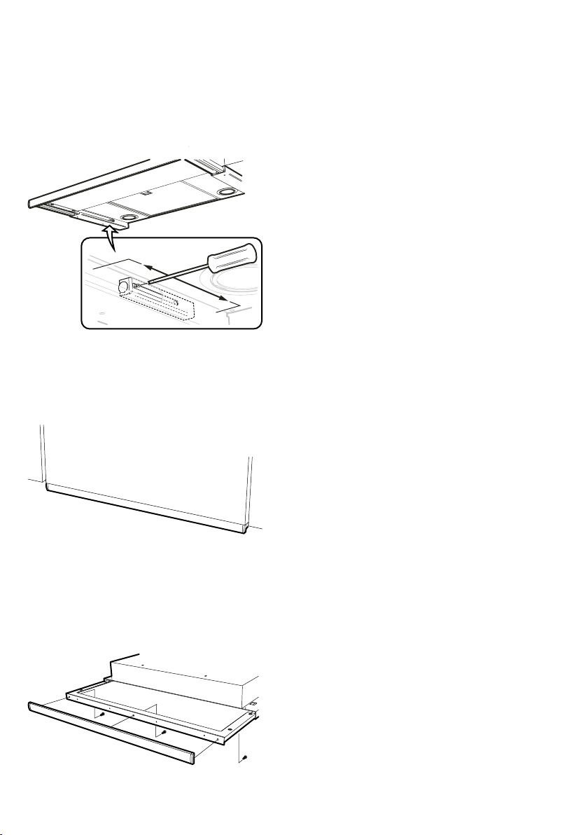
Adjusting the pull-out front.
Fig. 9
Pull the front out completely. Undo the
screw for the front stop, which is located
on the underside of the cooker hood, and
the pull it as far towards the front as pos-
sible, Fig. 9.
Fig. 10
Slide in the front until it is correctly positio-
ned in relation to the cupboards, Fig. 1 .
Pull out the front again and tighten the front
stop screw.
Changing front.
Fig. 11
The front is removable to enable replace-
ment with another front moulding. Undo
the screws according to Fig. 11.
991. 485.5 3/126239/2 17- 1-19 13
ADJUST NG A R FLOW
SETTING THE DAM ER
Basic flow
Fig. 12
Basic ventilation is set by moving the slid-
ing damper A to the desired position ac-
cording to marking B, Fig. 12. (See
diagram, page 24.)
Measuring pressure drop
Fig. 13
The pressure drop is measured by fitting
the hose on the measuring port E at the
front edge of the coupling, Fig. 13.
14 991. 485.5 3/126239/2 17- 1-19

NSTRUCT ONS FOR USE
FUNCTION CONTROLS
Fig. 14
A. Lighting
B. Damper
C. Indicator lamp (lit when damper open).
The damper is opened while food is being
prepared. The damper closes automatically
after 6 minutes or by pressing button B a
second time. Ideally, keep the damper open
a short while before and after cooking, in
order to avoid the spread of odours in the
room.
CARE AND MAINTENANCE
Cleaning
The cooker hood should be cleaned with a
damp cloth and washing-up liquid. The filter
must be cleaned twice a month, with nor-
mal usage.
Fig. 15
Remove the grease filter by opening the
snap, Fig. 15. Handle the filter gently, be
careful not to bend them.
Soak the filter in a solution of warm water
and washing-up liquid. The filter can also be
washed in a dishwasher.
Refit the grease filter after cleaning, make
sure they snap firmly into place.
The inside of the fan and the damper shall
be cleaned at least twice a year. Wipe with
a damp cloth and detergent. The damper is
best cleaned when it is open.
991. 485.5 3/126239/2 17- 1-19 15

SERV CE AND WARRANTY
Check that the fuse is intact. Go through all
the functions to check what does not work.
Contact Amalva/Komfovent
You will find the company's contacts in
www.komfovent.com website.
They can provide assistance with address-
ing the problem or point you to the nearest
service company for fast and effective
service.
The product is covered by the relevant EHL
provisions
Visit our website: www.komfovent.com
ACKAGING AND RODUCT
RECYCLING
The packaging should be deposited at
your nearest recycling collection point
The symbol means that the
product may not be treated as
household waste. It should in-
stead be submitted to a collec-
tion point for the recycling of
electrical and electronic components. By
ensuring that the product is handled in the
correct manner, you help to prevent the
possible negative environmental and health
effects that could occur if the product was
disposed of as regular waste. For further in-
formation on recycling, contact your local
authority or refuse disposal service, or the
store where you purchased your product.
16 991. 485.5 3/126239/2 17- 1-19

SAUGOS TA SYKLĖS
Prieš įrengdami ir pradėdami nau-
doti gaminį atidžiai perskaitykite
šią naudojimo ir montavimo in-
strukciją, ypač saugos taisykles.
Išsaugokite naudojimo instrukciją,
jei vėliau prireiktų jums patiems
arba tam, kam perduosite gaminį.
Prieš atlikdami bet kokio pobūdžio
valymą ar priežiūrą, išjunkite gami-
nį iš elektros tinklo.
§Šalinamas oras turi būti nukrei-
piamas laikantis taisyklių, nus-
tatytų atitinkamos institucijos.
§Šalinamo oro ortakio negalima
jungti prie dūmtraukio, kuris
yra naudojamas išmetamo-
sioms dujoms pašalinti iš, pa-
vyzdžiui, dujomis arba mediena
kūrenamų židinių, medžiu ar
skystu kuru kūrenamų katilų ir
t. t.
§Atstumas tarp viryklės ir gami-
nio turi būti mažiausiai 45 cm.
Jei naudojama dujinė viryklė,
padidinkite atstumą iki 65 cm.
Jeigu dujinės viryklės gaminto-
jas rekomenduoja didesnį auk-
štį, laikykitės jo
rekomendacijų.
§Kad išvengtumėte pavojaus,
įrengimo, laidų keitimo ir kitus
prijungimo darbus turi atlikti
kvalifikuotas specialistas.
§Naudojant gaminį draudžiama
ruošti maistą „flambé“ būdu
(užpilant spiritu ir padegant).
§Jei naudojant gaminį tuo pat
metu naudojami ir kiti gami-
niai, maitinami ne elektros
energija, pvz., dujomis arba
mediena kūrenami židiniai,
medžiu ar skystu kuru kūrena-
mi katilai ir t. t., į kambarį turi
pateikti pakankamas oro
kiekis.
§Gaminį gali naudoti vaikai nuo
8 metų amžiaus ir asmenys, tu-
rintys psichikos, sensorikos ar
fizinių sutrikimų arba menką
patirtį ir nedidelį žinių kiekį, jei-
gu jie yra informuoti apie tai,
kaip jį reikia naudoti.
§Vaikai negali žaisti su gaminiu.
Suaugusiųjų neprižiūrimiems
vaikams neleidžiama valyti
gaminio ir atlikti jo priežiūros
darbų.
§Gaminant maistą kai kurios
gaminio dalys gali įkaisti.
§Jei valoma rečiau nei rekomen-
duojama, padidėja gaisro
rizika.
991. 485.5 3/126239/2 17- 1-19 17
ĮRENG MAS
Numatyta, kad garų surinktuvas bus įreng-
iamas spintelėje. Garų surinktuve įtaisyta
motorinė sklendė, LED apšvietimas bei me-
talinis filtras. Šiose instrukcijose aprašytas
įrengimas, naudojimas, priežiūra ir kt.
TECHNINIAI DUOMENYS
Fig. 1
Matmenys žr. Fig. 1
Prijungimas prie
elektros tinklo
23 V ~ su
įžeminimu.
Apšvietimas LED lempa, 2 x 2
W
Didžiausia leistina
prijungimo galia
9 W, 23 V~
RIEDAI
Gofruotas vamzdis, skirtas prijungti prie vė-
dinimo kanalo.
ĮRENGIMAS
Montavimo detalės, tvirtinimo varžtai ir kt.,
parduodami kartu su gartraukiu.
rijungimas prie elektros tinklo
Prijungimas turi būti stabilus, o garų surink-
tuvas – įžemintas. Garų surinktuvą turi
įrengti kompetentingas specialistas.
Fig. 2
Sklendės angos pakeitimas
Jeigu garų surinktuvas bus montuojamas
virtuvėje, kurioje yra atskira vėdinimo siste-
ma, jo sklendės anga turi sandariai užsida-
ryti. Prieš montuodami garų rinktuvą,
pakeiskite gartraukio perėjimą į angą (žr.
atskirai pateiktas gaires).
Sklendės montavimas
Fig. 3
Ortakio jungtis su sklende pateikiama garų
surinktuvo viduje.
Sklendės ašis A įstatoma į kilpą po sklen-
dės dangčiu, žr. Fig. 3. Patikrinkite, ar an-
tgaliai atsirado po plokštės kraštu ir ar
įtaisas įsitvirtino.
18 991. 485.5 3/126239/2 17- 1-19

Garų surinktuvo įrengimas
Įrengimas spintelėje be dugno arba tarp
spintelių.
Fig. 4
Garų surinktuvas montuojamas naudojant
atramas.
Pažymėkite ir pritvirtinkite varžtus taip, kad
jie išsikištų pora milimetrų abiejuose spin-
telės šonuose, kaip parodyta paveikslėlyje,
Fig. 4A. Jeigu norite, kad garų surinktuvo
apačia būtų vienoje eilėje su spintelių apa-
čia, naudokite viršutinį matą, 1 2, žr. Fig. 4
A. Garų surinktuvo atramos yra reguliuoja-
mos, kad atitiktų skirtingus spintelių gylius,
Fig. 4 B.
Fig. 5
Sumontuokite atramas į garų surinktuvą iki
galo neišimdami varžtų ir sureguliuokite jas
taip, kad jos atitiktų spintelės sienas, Fig. 5
A. Pakabinkite garų surinktuvą ant jau
sumontuotų varžtų. Priveržkite varžtus atra-
moje ir sienoje, Fig. 5B. Užtvirtinkite atra-
mas varžtais su veržlėmis, Fig. 5C.
Įrengimas spintelėje su dugnu.
Fig. 6
Fig. 7
Garų surinktuvas montuojamas naudojant
atramas.
Išpjaukite angą spintelės dugne pagal pa-
veikslėlį, Fig. 6. Įtvirtinkite atramą kuo gi-
liau. Pastumkite gartraukį į angą spintelės
apačioje. Ištraukite, Fig. 7A, prisukite atra-
mas spintelės šonuose, Fig. 7B. Priveržkite
atramas prie garų surinktuvo.
Prijungimas prie išeinančio oro kanalo
Prijunkite gartraukį lanksčiu ar cinkuotos
skardos ortakiu, kurio skersmuo - 125 mm.
Fig. 8
991. 485.5 3/126239/2 17- 1-19 19
Obs!
Prijungiamoji žarna montuojama ištiesta,
tiesiai į artimiausią prijungimo vietą, Fig.
8.
Nuimamos priekinės dalies
reguliavimas.
Fig. 9
Iki galo ištraukite priekinę dalį. Atlaisvinkite
varžtus, laikančius priekinės dalies viršų
garų surinktuvo apačioje ir patraukite ją į
priekį tiek, kiek įmanoma, Fig. 9.
Fig. 10
Traukite priekinę dalį tol, kol ji bus tinkamo-
je padėtyje, Fig. 1 . Dar kartą patraukite
priekinę dalį ir priveržkite priekinės dalies
viršų.
riekinės dalies pakeitimas.
Fig. 11
Priekinė juostelė gali būti nuimama ir pakei-
čiama kitokia. Atsukite varžtus pagal Fig.
11.
2 991. 485.5 3/126239/2 17- 1-19
Table of contents
Languages:
Other Komfovent Ventilation Hood manuals

Popular Ventilation Hood manuals by other brands

KLARSTEN
KLARSTEN REMY 10031996 manual

Thermador
Thermador HPCN36WS installation instructions

Miele
Miele DA 424 V EXT Operating and installation instructions

Gurari
Gurari GCH F 462 Manual for installation and use

Electrolux
Electrolux EFC 950 Operating and installation instruction

KOBE
KOBE RA92 Series Installation instructions and operation manual


Harbor Freight Tools
Harbor Freight Tools 90787 Assembly and operating instructions

Akrapovic
Akrapovic Slip-on installation instructions

Beko
Beko BHCA96641BBBHS user manual

American Standard
American Standard QR031 owner's manual

Russell Hobbs
Russell Hobbs RHGCH702B-M instruction manual

Alpes Inox
Alpes Inox ARGENTO E 193 instruction manual