RECOMMENDATIONS AND SUGGESTIONS 4
RECOMMENDATIONS AND SUGGESTIONS
The Instructions for Use apply to several versions of this appliance. Accordingly, you
may find descriptions of individual features that do not apply to your specific appli-
ance.
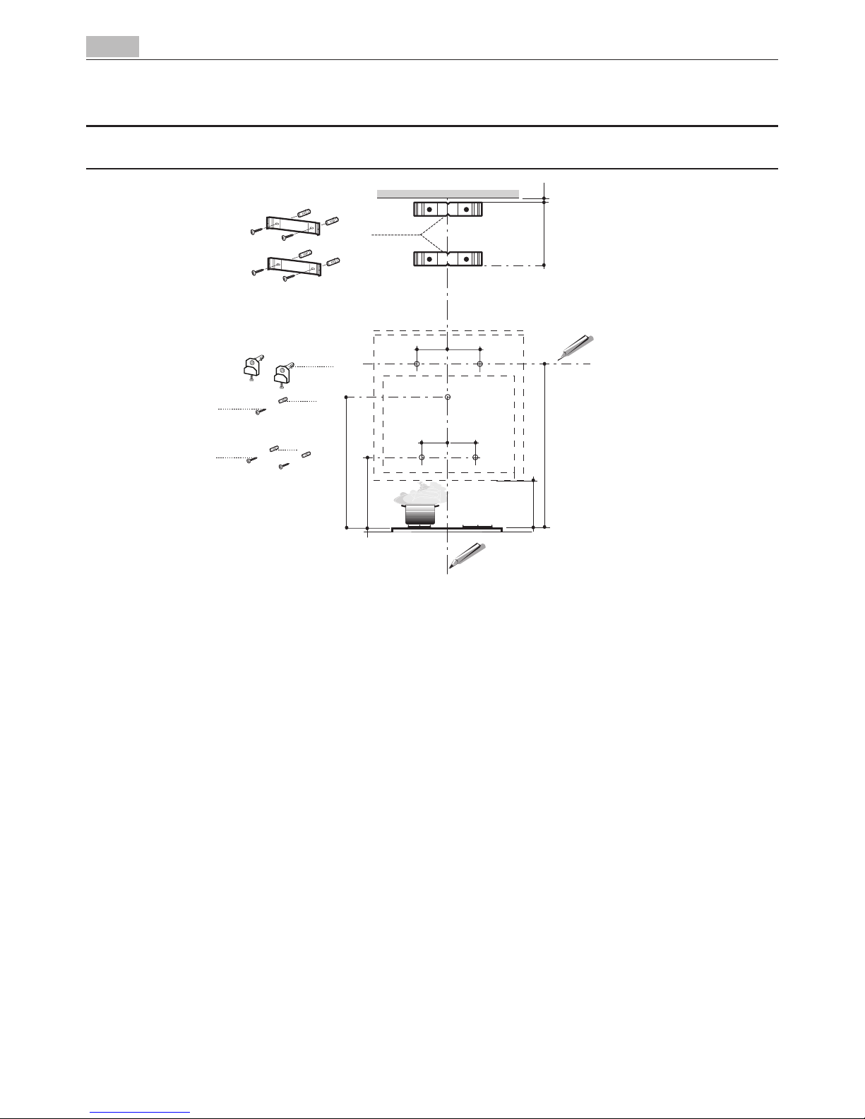
INSTALLATION
• Themanufacturerwillnotbeheldliableforanydamagesresultingfromincorrector
improper installation.
• Theminimumsafetydistancebetweenthecookertopandtheextractorhoodis650mm
(some models can be installed at a lower height, please refer to the paragraphs on work-
ing dimensions and installation).
• Checkthatthemainsvoltagecorrespondstothatindicatedontheratingplatefixedto
the inside of the hood.
• ForClassIappliances,checkthatthedomesticpowersupplyguaranteesadequateearth-
ing.
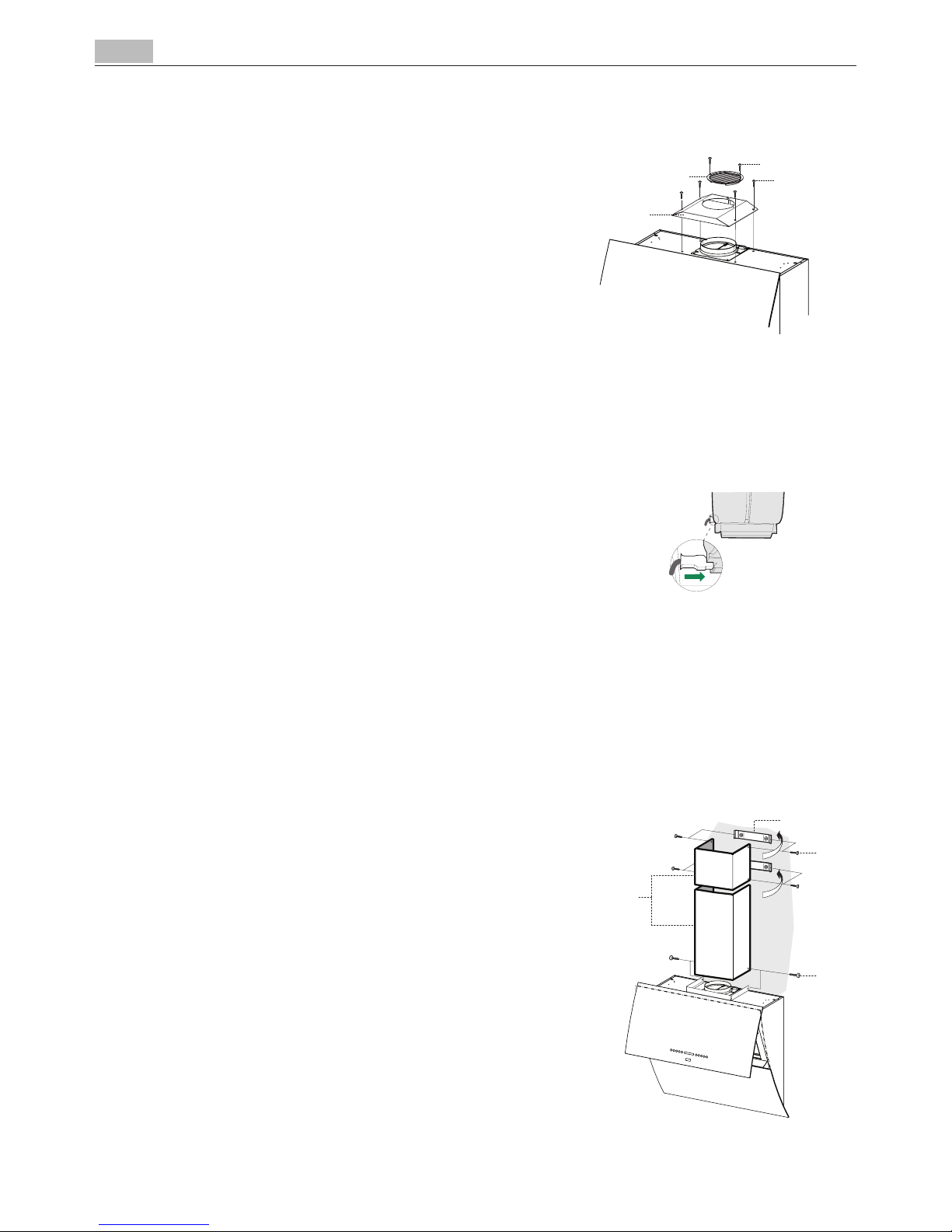
Connect the extractor to the exhaust flue through a pipe of minimum diameter 120 mm.
The route of the flue must be as short as possible.
• Donotconnecttheextractorhoodtoexhaustductscarryingcombustionfumes(boilers,
fireplaces, etc.).
• Iftheextractorisusedinconjunctionwithnon-electricalappliances(e.g.gasburning
appliances), a sufficient degree of aeration must be guaranteed in the room in order to
prevent the backflow of exhaust gas. The kitchen must have an opening communicating
directly with the open air in order to guarantee the entry of clean air.
USE
• Theextractorhoodhasbeendesignedexclusivelyfordomesticusetoeliminatekitchen
smells.
• Neverusethehoodforpurposesotherthanforwhichithasbendesigned.
• Neverleavehighnakedflamesunderthehoodwhenitisinoperation.
• Adjusttheflameintensitytodirectitontothebottomofthepanonly,makingsurethat
it does not engulf the sides.
• Deepfatfryersmustbecontinuouslymonitoredduringuse:overheatedoilcanburstinto
flames.
• Donotflambèundertherangehood;riskoffire
• Thisapplianceisnotintendedforusebypersons(includingchildren)withreducedphysi-
cal, sensory or mental capabilities, or lack of experience and knowledge, unless they have
been given supervision or instruction concerning use of the appliance by a person re-
sponsible for their safety.
• Childrenshouldbesupervisedtoensurethattheydonotplaywiththeappliance.
MAINTENANCE
• Switchofforunplugtheappliancefromthemainssupplybeforecarryingoutanymain-
tenance work.
• Cleanand/orreplacetheFiltersafterthespecifiedtimeperiod(Firehazard)
• Cleanthehoodusingadampclothandaneutralliquiddetergent.
The symbol on the product or on its packaging indicates that this product may not be treated as household waste. Instead it shall be
handed over to the applicable collection point for the recycling of electrical and electronic equipment. By ensuring this product is disposed
of correctly, you will help prevent potential negative consequences for the environment and human health, which could otherwise be
caused by inappropriate waste handling of this product. For more detailed information about recycling of this product, please contact your
local city office, your household waste disposal service or the shop where you purchased the product.