Komfovent DOMEKT R 200 V Manual

DOMEKT
EN Installation and service Manual

UAB AMALVA we reserve the right to make changes without prior notice 3
D2-18-01
This symbol indicates that this product is not to be disposed of with your household waste, according to the
WEEE Directive (2002/96/EC) and your national law. This product should be handed over to a designated
collection point, or to an authorised collection site for recycling waste electrical and electronic equipment (EEE).
Improper handling of this type of waste could have a possible negative impact on the environment and human
health due to potentially hazardous substances that are generally associated with EEE. At the same time, your
cooperation in the correct disposal of this product will contribute to the effective usage of natural resources. For
more information about where you can drop off your waste equipment for recycling, please contact your local city
ofce, waste authority, approved WEEE scheme or your household waste disposal service.
Content
1. SAFETY REQUIREMENTS ............................................................................................................................ 4
2. TRANSPORTATION........................................................................................................................................ 4
3. BRIEF DESCRIPTION OF THE UNIT ........................................................................................................... 5
4. INSTALLATION ............................................................................................................................................. 12
4.1. Condensate Drain Connections ............................................................................................................... 16
4.1.1. Water trap installation for a unit section mounted on the suction side........................................... 17
4.1.2. Water trap installation for a unit section mounted on the pressure side ........................................ 17
4.2. Heating coil connection............................................................................................................................ 24
4.3. Ductwork .................................................................................................................................................. 24
4.4. Final Inspection........................................................................................................................................ 25
5. MAINTENANCE............................................................................................................................................. 25
6. TECHNICAL INFORMATION ....................................................................................................................... 26

EN
UAB AMALVA we reserve the right to make changes without prior notice
4
D2-18-01
1. SAFETY REQUIREMENTS
• To avoid accidents and/or unit damage, only a trained technician must
carry out the connection.
• The appropriate Personal Protective Equipment (PPE) attire is worn
relative to the operation being carried out.
• Electrical equipment is rated, connected and earthed in accordance
with CE regulations.
The air handling unit must be plugged in to an electrical outlet (with earth), which is in good order and corre-
sponds with all requirements of electric safety. Before starting any operations inside the unit, make sure that
the unit is switched off, and the power cable is unplugged.
• Earth must be installed according EN61557, BS 7671.
• The unit should be installed according to Installation and Maintenance
Manual.
• Before starting the unit, check correct position of air lters.
• Service maintenance should be carried out only in conformity with the
instructions specied herein below.
• If main cable is damaged, only manufacturer, service team or trained
technician must change it in order to avoid accidents.
2. TRANSPORTATION
The air handling units are ready for transit and storage (1 Picture). The unit is packed to prevent damage of the
external and internal parts of the unit, dust and moisture penetration.
Corners of the air handling units are protected against the damage – protective corners are used. The en-
tire unit is wrapped up in protective lm. For transit or storage, units are mounted on timber pallets. The unit is
fastened to the pallet with polypropylene packing tape over protective corners.
Vertical and horizontal units ready for transit and storage
1 Picture
UAB AMALVA we reserve the right to make changes without prior notice 5
D2-18-01
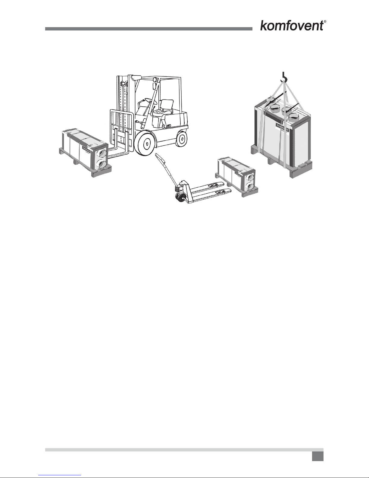
When unit is loaded or unloaded by crane, cargo rope is fastened in its designated places.
Forklift truck or hand pallet truck can transport air handling unit as it is shown (2 a, b, c Pictures).
Vertical and horizontal unit transportation by forklift truck, hand pallet truck or crane
2 a Picture 2 c Picture
2 b Picture
2 a Unit is transported by forklift truck on a wooden pallet;
2 b Unit is transported by hand pallet truck on a wooden pallet;
2 c Unit is lifted by crane on a wooden pallet.
The unit should be examined upon receipt, to ensure that no visible damage has occurred during transit, and
the advice note checked to ensure that all items have been received. If damage or delivery shortages are disco-
vered, the carrier should be immediately informed. AMALVA should be notied within three days of receipt, with
a written conrmation sent within seven days. AMALVA can accept no responsibility for damage by unloading
from carrier or for subsequent damage on site.
If the unit is not to be installed immediately, it should be stored in a clean, dry area. If stored externally, it
should be adequately protected from the weather.
3. BRIEF DESCRIPTION OF THE UNIT
• The air handling units are intended for ventilation of small and medium-sized spaces (eg. single family
houses, ofces, etc.), having operating ambient temperature and relative humidity. The unit is intended to
be installed in the domestic or non residential premises. Mineral wool is used for thermal insulation and
sound attenuation. Units cover panels are 25–50 mm thick. As standard, the unit is designed for indoor
placement. In cold, wet rooms possible icing or condensation on the housing inside and outside. The op-
erating temperature range for the unit is -30 °C ... +40 °C, outdoor air temperature. Extracted indoor air
temperature +10 – +40 °C, relative humidity (non-condensing) 20–80 %.
• The air handling unit is not to be used to transport solid particles, even not in areas where there is a risk of
explosive gases.
• The units are equipped with a rotary heat exchanger or with a plate heat exchanger (may be replaced with
summer cassette, when recuperation is needless), air lters, an electric or water heater, fans and automa-
tion control system, to ensure safe and efcient operation of the unit.
• Before you open the door, the unit must be switched off and the fans must have been given time to stop (up
to 3 minutes).
• The unit contains heating elements that must not be touched when they are hot.
• We recommend to leave air handling unit in working mode (minimum 20 percent of power) during the rst
operation year. Due to moisture in building constructions, condensation may occur inside and outside the
air handling unit. Continuous operation of the equipment will signicantly reduce the risk of condensation.
EN
UAB AMALVA we reserve the right to make changes without prior notice
6
D2-18-01
• To maintain a good indoor climate, comply with regulations and, to avoid condensation damage, the unit
must never be stopped apart from during service/maintenance or in connection with an accident.
• If the unit is placed in spaces with high humidity, condensation might occur on the surface of the unit when
outdoor temperatures are very low.
• Under conditions, when the outdoor air temperature is low and humidity is high, risk of heat exchanger
frosting may appear. For this reason anti-frost protection function is foreseen in the controller of the Kom-
fovent air handling units. Depending on the type of the recovery, different methods of anti-frost protection
are available: cold air by-passing, or / and supply air fan speed reducing. For extremely low outdoor air
temperature the duct mounted preheater is recommended. Counter cross ow heat exchanger is the mostly
sensitive for low outside air temperatures, as the risk of frosting appears in the temperature range from
0 to -5 °C and below. Standard aluminium cross-ow plate heat exchanger has better features, as the risk
of freezing appears only at -10 °C. The lowest risk and the highest resistance to cold outside air is a com-
petitive feature of the rotary heat exchanger, as it is not freezing even at the temperatures of -30 °C if the
humidity level of the air is appropriate.
• Selecting the management without pre-heater, but with cold air bypass the unit must be additionally
equipped with a secondary duct mounted heater.
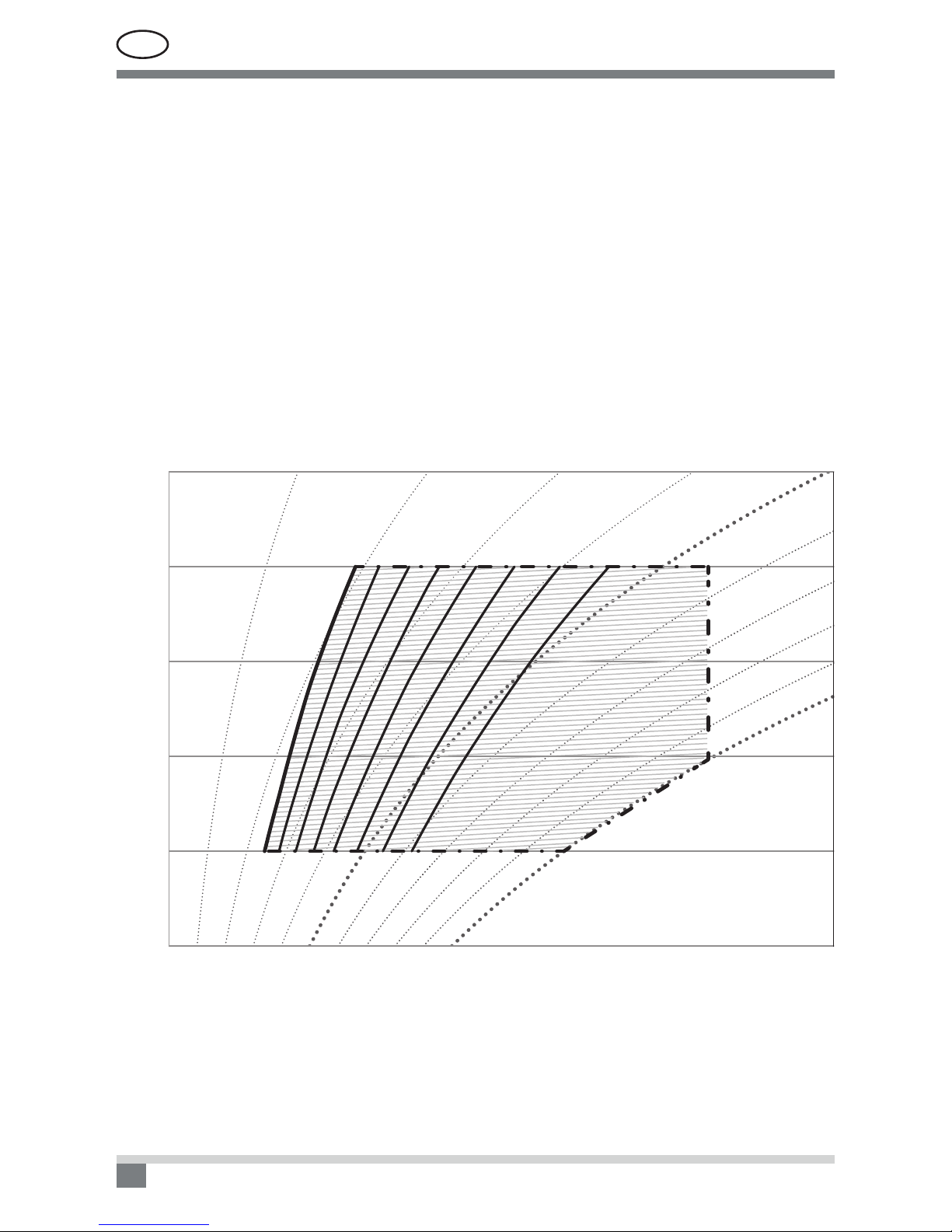
During air handling unit operation the process of condensation could be caused because of cold outdoor air
or due to high ambient air humidity (3 picture).
Indoor humidity
35
30
25
20
15
10
Indoor temperature, °C
10% 20% 30% 40% 50%
60%
70%
80%
90%
100%
Outside temperature, °C
-25 -20 -15 -10 -5 0510
3 picture. Condensation on unit surface diagram
UAB AMALVA we reserve the right to make changes without prior notice 7
D2-18-01
Suppose that supply air temperature is -25°C. Ambient air temperature, where air handling unit is installed,
is +20°C. In this case, condensate may appear on the outer surfaces of the air handling unit when relative hu-
midity in room is in range from 23% up to 100% (from point where curves of outside and inside air temperatures
crosses till the maximum value).
In other case, suppose that supply air temperature is 0°C. Indoor air temperature where air handling unit
is installed is +20°C. In this case, condensate may appear on the outer surfaces of the air handling unit when
relative humidity in room is in range from 43% up to 100% (from point where curves of outside and inside air
temperatures crosses till the maximum value).
To avoid condensation on unit outer surface use following solutions:
1) There should be maintained a lower relative humidity in the room where air handling unit is installed;
2) Preheater should be installed to increase the supply air temperature
EN
UAB AMALVA we reserve the right to make changes without prior notice
8
D2-18-01
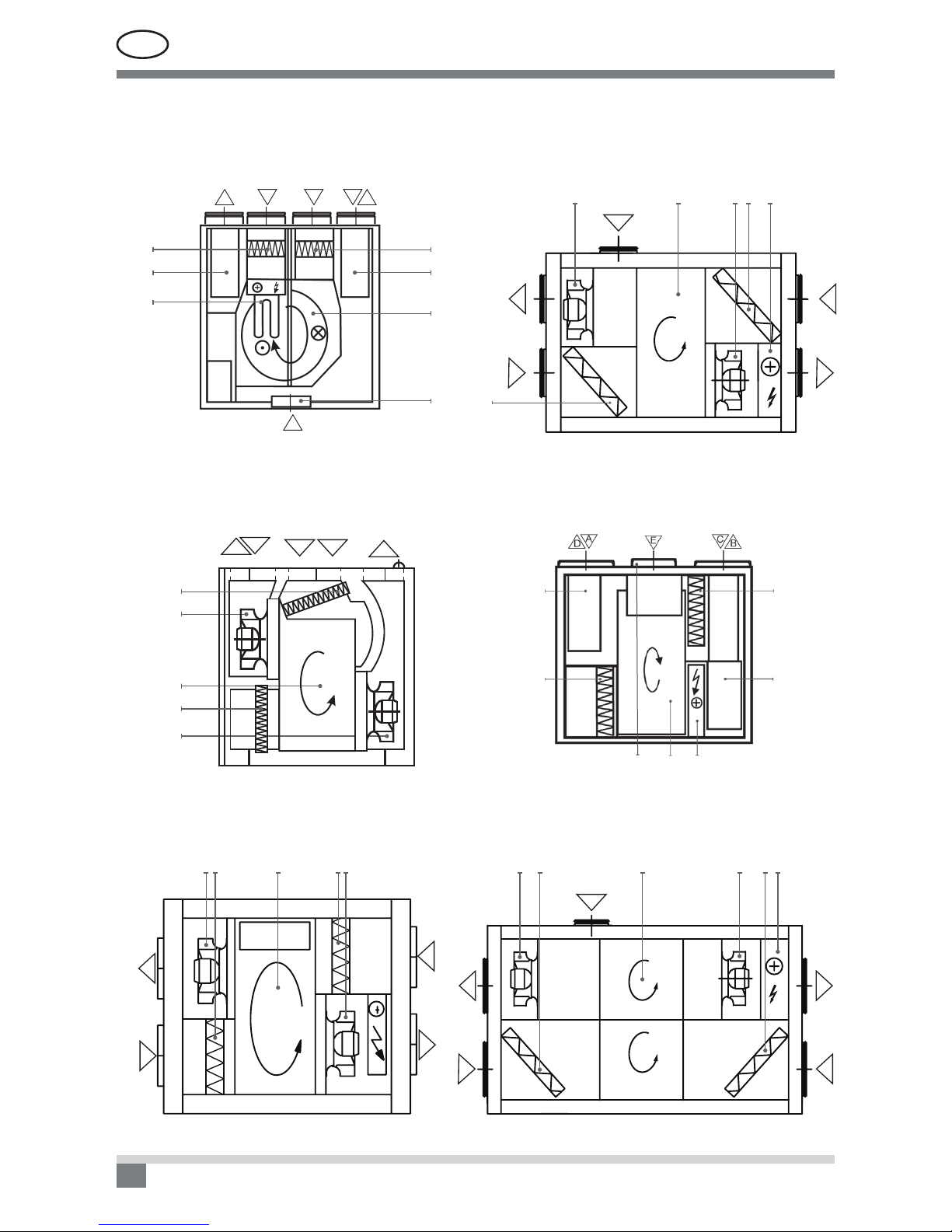
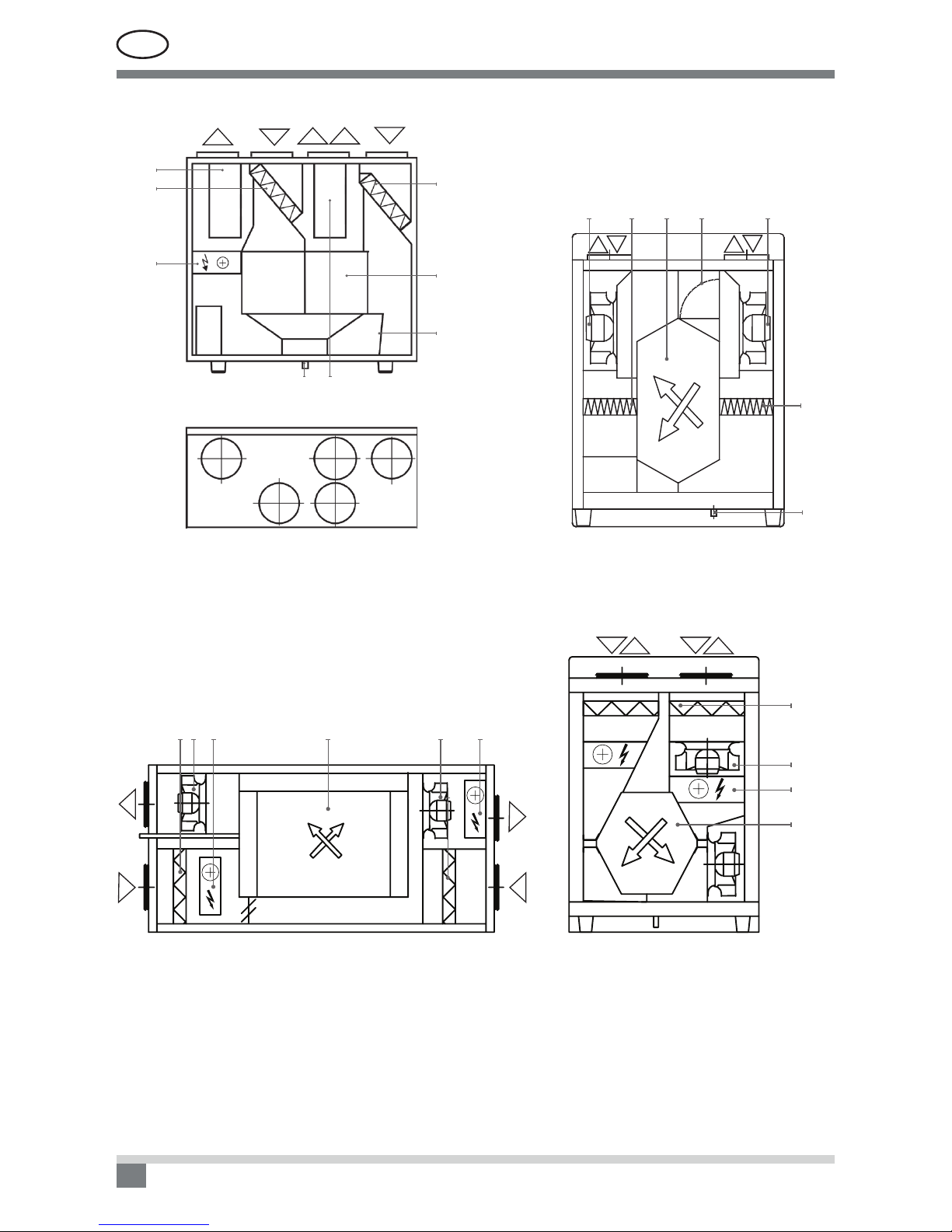
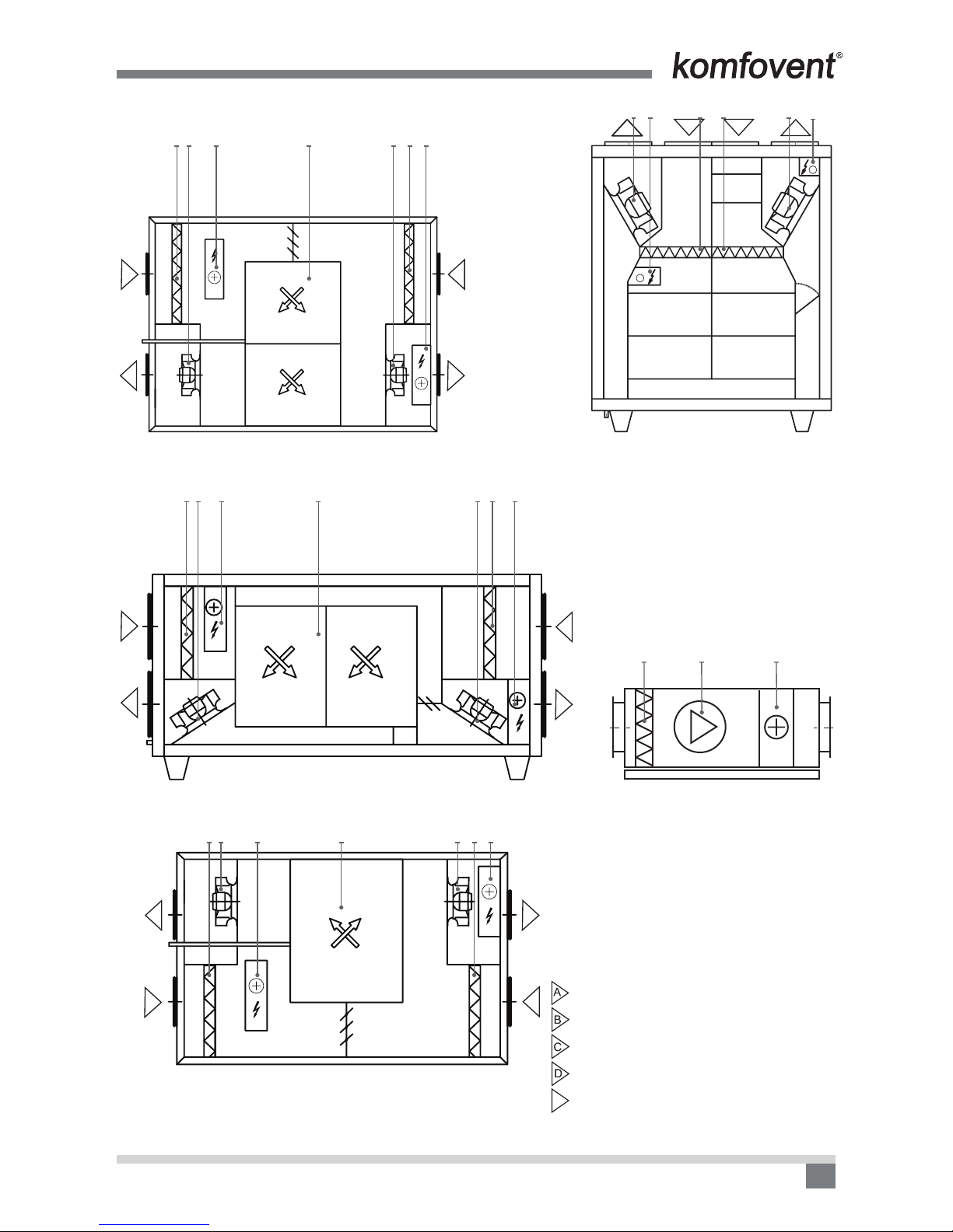
Air Handling Units Schemes
6
3
4
5
712
DOMEKT R 400 V / DOMEKT R 450 V
5
2
7
4
3
6
1
BA C E D
E
DOMEKT R 200 V
6
3
1
5
4
C
BA E D
DOMEKT R 300 V
D
A
C
B
341 5
6
DOMEKT R 400 H
E
D
A
C
B
3
4
156 2
DOMEKT R 250 F C6
C
B
A
D
E
6 3 1 5 4 2
DOMEKT R 400 F

UAB AMALVA we reserve the right to make changes without prior notice 9
D2-18-01
E
D
A
C
B
6 3 1 54 2
DOMEKT R 700 H
A
D
E
C
B
63 1 4 5 2
DOMEKT R 500 H C6
D
A
E
C
B
63 1 45 2
DOMEKT R 600 H
B
E
ADC
2
5
4
3
6
1
DOMEKT R 500 V** / DOMEKT R 700 V**
C
BD
A
2 6 13 54
DOMEKT R 700 F
EN
UAB AMALVA we reserve the right to make changes without prior notice
10
D2-18-01
ADCB
3
6
2
1
DOMEKT CF 400 V
CD
43
1
5
68
BEA
2
7
BCEDA
DOMEKT PP 300 V / 450 V
6 3 1 7 5
4
8
DABC
DOMEKT CF 250 V
D
A
B
C
1263 5
4
2
DOMEKT CF 250 F
UAB AMALVA we reserve the right to make changes without prior notice 11
D2-18-01
A
D
C
B
1
263 5 24
DOMEKT CF 500 F
B
C
D
A
1
263 5 24
DOMEKT CF 700 F
A
D
C
B
1
263 5 24
DOMEKT CF 700 H
+
+
DACB
623 4 5 2
DOMEKT CF 700 V
4 6 3
DOMEKT S 650 F / 800 F
A. Outdoor intake
B. Supply air
C. Extract indoor
D. Exhaust air
EE. Kitchen hood connection
(by-pass – extraction without heat recovery)
1. Rotary or plate heat exchanger
2. Electric or water air heater
3. Supply air lter
4. Exhaust air lter
5. Supply fan
6. Exhaust fan
7. Air by-pass damper
8. Condensate drain (the water trap must be installed)
EN
UAB AMALVA we reserve the right to make changes without prior notice
12
D2-18-01
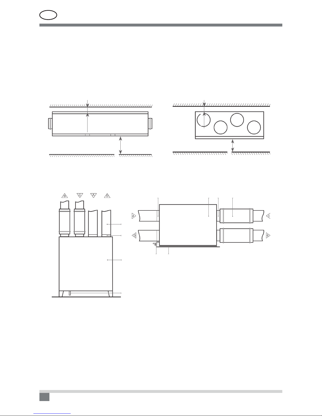
4. INSTALLATION
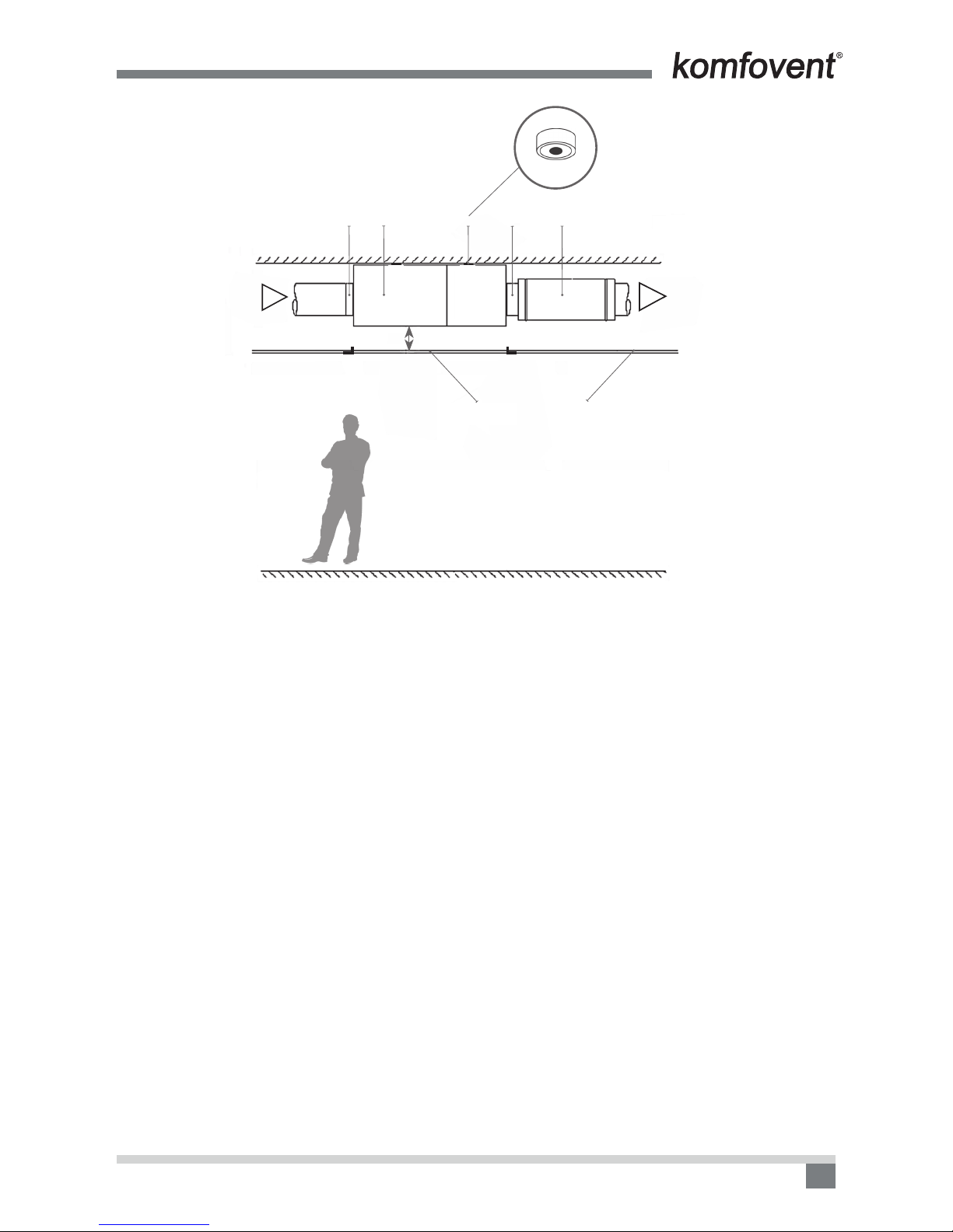
It is recommended to install the air handling unit in a separate room or in the attic on a hard smooth surface
insulated with a rubber mat. The minimum free space in front of the control panel should be not less than
700 mm. The free space over the top of the unit should be at least 300 mm (4 a, b Picture). Rubber vibration
absorbers must be used when unit is going to be mounted on the wall or ceiling.
The place for the unit must be selected with allowance for minimum access to the unit for maintenance or
service and must comply with safety requirements. Opening for inspection can not be smaller than dimensions
of the unit and unit itself must be mounted in a way, that if needed (for example in case of complicated repair)
it can be easily dismounted.
Minimum Maintenance Space for Horizontal Units
100 mm
min. 700 mm
4 a Picture
Minimum Maintenance Space for Vertical Units
100 mm
min. 700 mm
4 b Picture
Unit Installation Scheme
23
12
4 5
2
1
3
4
1. Air handling unit
2. Air duct connections
3. Sound attenuator
4. Drain siphon (if provided)
5. Rubber vibration absorber (not included in unit set)
4 Picture
UAB AMALVA we reserve the right to make changes without prior notice 13
D2-18-01
B
ceiling
A
min. 100 mm
5
B
1
Inspection
trapdoor
223
5 Picture
EN
UAB AMALVA we reserve the right to make changes without prior notice
14
D2-18-01
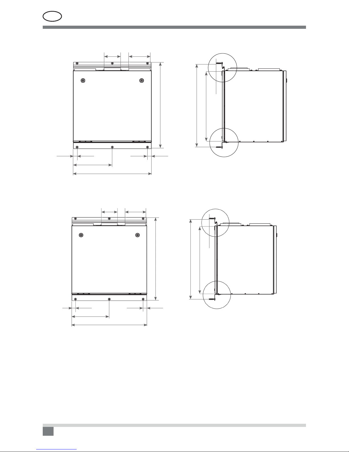
DOMEKT R 400 V Unit brackets’ positions
B
A
641
604
57
662
30
300
600
30
Ø125 Ø160
6 Picture
DOMEKT R 450 V Unit brackets’ positions
Ø125 Ø160
A
57
667
704
B
30
340
30
680
7 Picture
UAB AMALVA we reserve the right to make changes without prior notice 15
D2-18-01
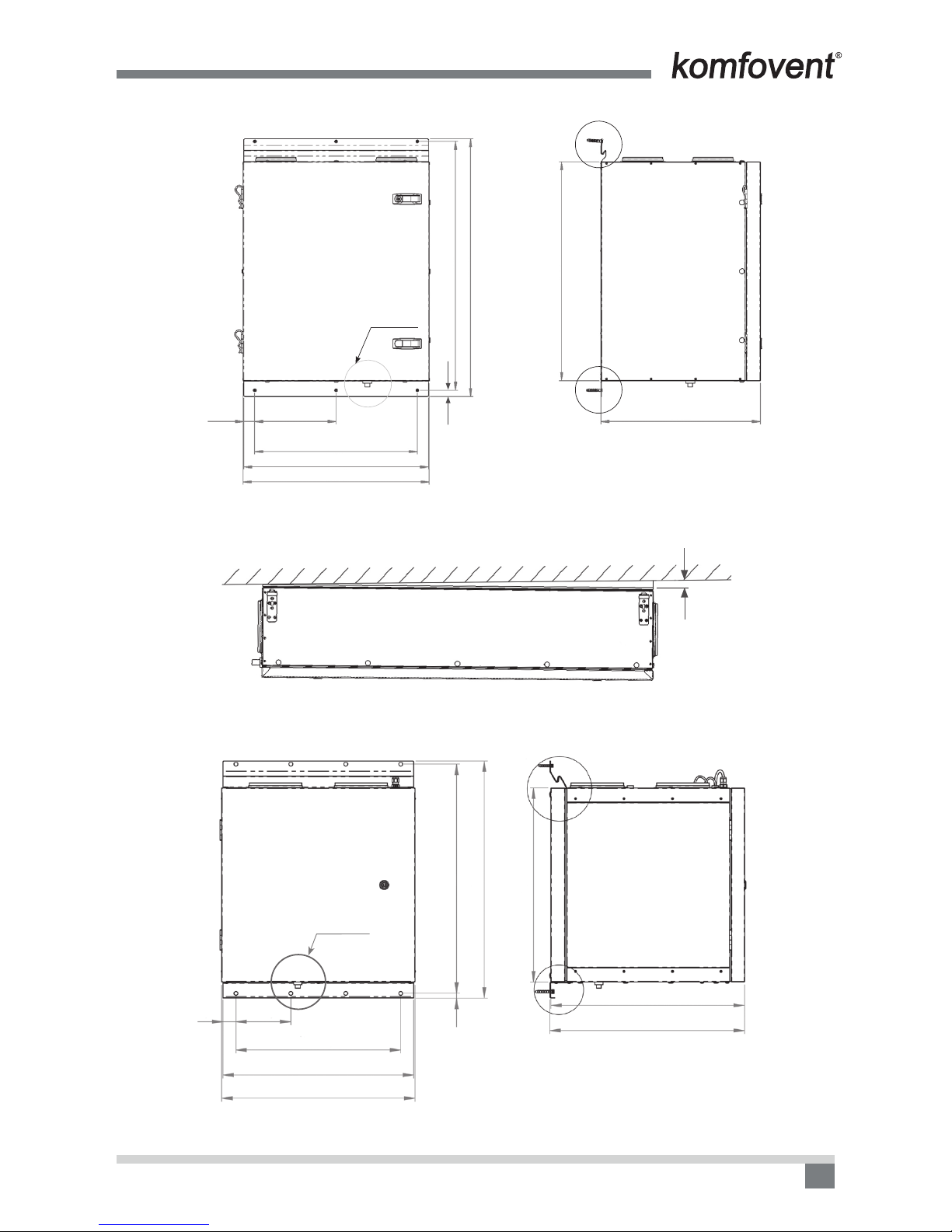
Įrenginio DOMEKT CF 250 V Unit brackets’ positions
view 1
35 260
520
590
595
20
B
A
510
700
824
795
8 Picture
DOMEKT CF 250 F Unit brackets’ positions
15
9 Picture
DOMEKT CF 400 V Unit brackets’ positions
view 1
40 170
3 × 170 = 510
590
598
15 709
734
600
600
603
A
B
10 Picture
EN
UAB AMALVA we reserve the right to make changes without prior notice
16
D2-18-01
4.1. Condensate Drain Connections
All condensate drain connections must be correctly trapped. Incorrect trapping can result in ooding within the
unit and consequent ooding of the immediate area. Fill the drain trap with water before starting up the unit.
All drain lines should be insulated where passing through any space where damage from condensation
drip might occur. If the unit is installed in unheated premises the condensate pipe should be heat-insulated and
heated with heating cable.
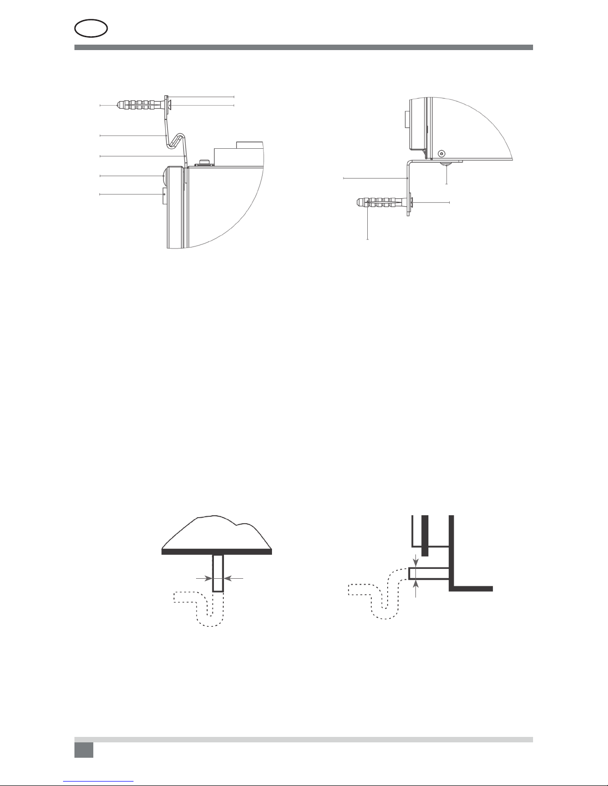
A condensate pipe and a drain trap
Drain scheme of Vertical Unit
view 1
D = 15
12 a Picture
Drain scheme of Horizontal Unit
view 2
D = 15
view 2
12 b Picture
The bend of the water trap can be repositioned by turning it to the right or the left. The drain line from the
water trap must be arranged so that it will not damage adjacent unit sections or building elements. If the drain
line is run through cold spaces, it should be insulated to prevent freezing. A heating cable may be required.
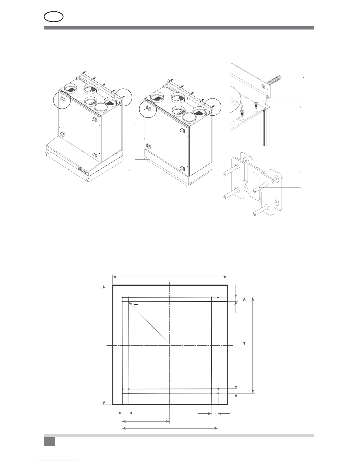
Pictures 11 a and 11 b show unit’s upper and bottom xing element.
2
3
4
5
6
9
1
8
2
7
1
11 a Picture 11 b Picture
1. Screw
2. Wall plug
3. Hanging bracket 1
4. Hanging bracket 2
5. Bolt M5
6. Gasket
7. Self tapping screw
8. L-shape bracket
9. Washer M5 DIN9021

UAB AMALVA we reserve the right to make changes without prior notice 17
D2-18-01
4.1.1. Water trap installation for a unit section mounted on the suction side
Since the fans in most air handling units are last in the chain of functions and generate sub-atmospheric pres-
sure inside the unit,it is very important to correctly install the water trap. Because of that reason condensate
can be hardly eliminated from the air handling unit and the technical premise may get covered with condensate.
Height H1must be at least equivalent in mm to half of the negative pressure inside the unit in mm water gauge.
Height H2must be at least equivalent in mm to the negative pressure inside the unit in mm water gauge.
Ø 32
25-240106
DN 40
95
H1, H2
140-310
Condensate Condensate
H2
H1
Precaution: The drainage siphon should be mounted on the outlet t-
ting pipe of every drip tray for complete condensate drainage from the air
handling unit and prevention of penetration of offensive odours from an
efuent into the ventilation system.
In case of the outdoor operation of the air handling unit, the siphon and
the bleeders should be heated with an electric thermal cable (if ambient
air temperature tamb < 0 °C). The siphon and the bleeders should be heat-
insulated with an insulating material.
4.1.2. Water trap installation for a unit section mounted on the pressure side
Since the fans in most air handling units are not last in the chain of functions and generate over-atmospheric
pressure inside the cooling section. In such case the consisted condensate can be easily removed from AHU
and there will be no strict requirements for siphon‘s installation. A drainage siphon is enough with a minimum
rake.
RECOMMENDATION: The drainage siphon must be installed in connection with not less size pipe diameter.
Any drainage systems must not be connected directly to the municipal sewage system. The condensate tray
shall be easily accessible for cleaning and disinfection.
EN
UAB AMALVA we reserve the right to make changes without prior notice
18
D2-18-01
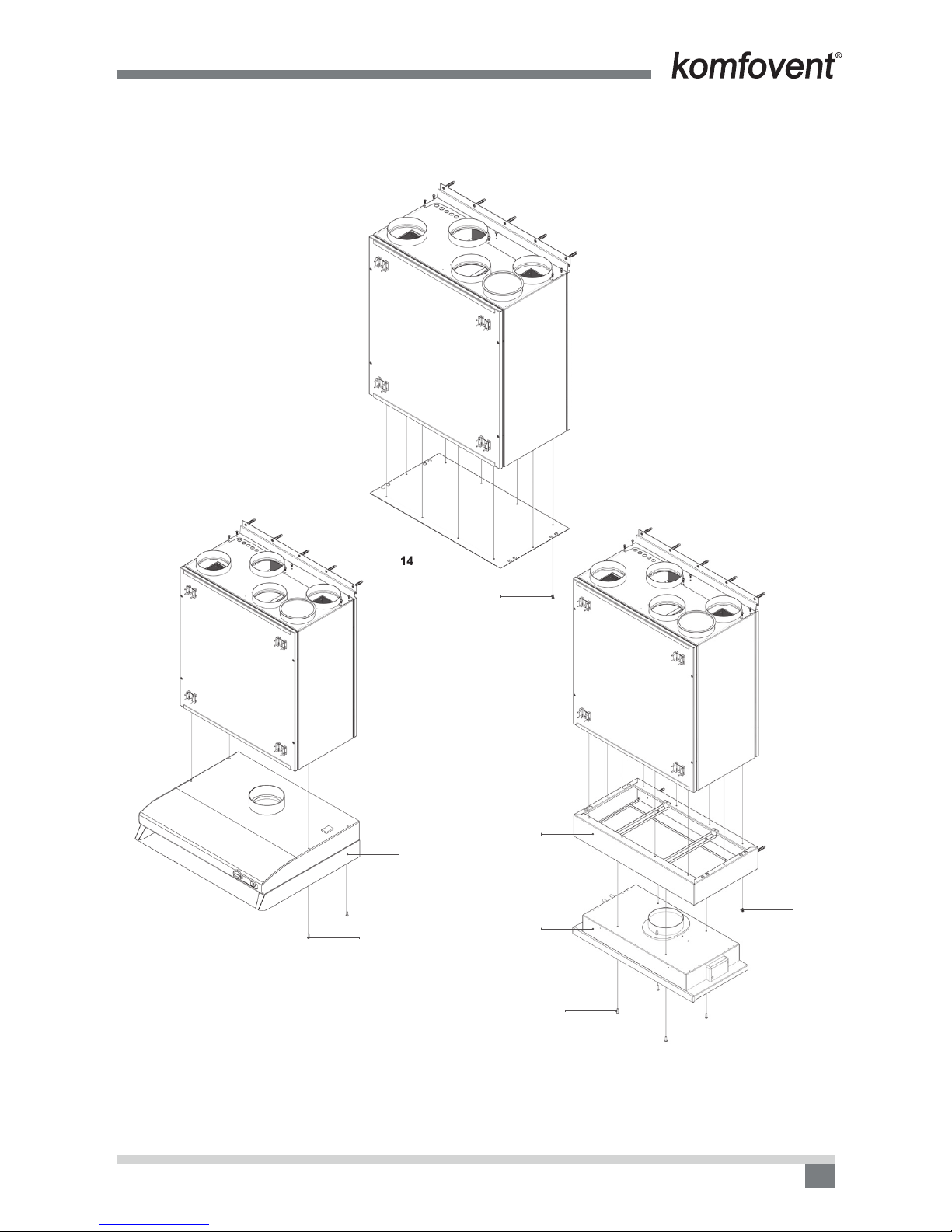
DOMEKT R 200V unit with kitchen hood
Air handling unit DOMEKT R 200 V can be mounted with one of the two types of kitchen hoods (13, 14 Picture).
1. Air handling unit DOMEKT R 200V
2. Kitchen hood adapter 392-12
3. Kitchen hood 392-12
4. Standard kitchen hood
5. Wall plug 8×50 + screw 4,5×50
6. Wall mounting bracket
7. Unit bracket
8. Self tapping screw 4,2×13
9. Bracket for decorative panel
10. Screw 2.5×16 with cone head
Dimensions for mounting furniture panel
22
625
600
500
250
22
32.5
500
250
32.5
Ø 2(depth – 5 mm) 16 holes
13 Picture
1
9
2
3
4
A
B
BA
A
B
5
6
7
8
9
10
UAB AMALVA we reserve the right to make changes without prior notice 19
D2-18-01
14a Picture
5 (×10)
Instalation scheme of DOMEKT R 200V unit with kitchen hood
Before installing kitchen hood, bottom cover plate must be removed by remooving xing screws (14a pic.)
14b Picture. Installation of standard kitchen hood 14c Picture. Installation of kitchen hood 392-12
1. Kitchen hood adapter 392-12
2. Standard kitchen hood
3. Kitchen hood 392-12
4. Screws M4 for hood xation (4 picture)
5. Self tapping screws 4,2×13 for adapter xation (10 picture)
5 (×10)
4 (×4)
4 (×4)
3
2
1

EN
UAB AMALVA we reserve the right to make changes without prior notice
20
D2-18-01
Dimensions for the DOMEKT R 200 V installation space
804
42
320
625
~777
500
140
140 × 4 = 560
575
600
15 Picture. Dimensions with standard kitchen hood
16 Picture. Dimensions with kitchem hood 392-12
320
42
738
94
625
140×4 = 560
140
25
600
This manual suits for next models
12
Table of contents
Popular Ventilation manuals by other brands

nilan
nilan Compact P installation instructions

Genvex
Genvex GES Energy S installation manual

DVS
DVS Positive Pressure Home Ventilation System operating guide

Fantech
Fantech 405335 installation manual

Monodraught
Monodraught Cool-phase Nova operating & maintenance manual

GE
GE UVB30 Owner's Manual & Installation Instructions


