nilan Compact P User manual

Installation Instructions
for
Compact P
Version 5.02, 07.01.2011

Contents
Contents......................................................................................................................................... 2
Figure table .................................................................................................................................... 2
Before starting................................................................................................................................ 4
Electrical connection....................................................................................................................... 5
Installing Compact P....................................................................................................................... 6
Condensation drain/water trap........................................................................................................ 9
Water connection.......................................................................................................................... 10
Duct connection............................................................................................................................ 12
Supplementary heating element DHW.......................................................................................... 13
Start-up and configuration of CTS602 controls............................................................................. 14
Startup...................................................................................................................................... 14
CTS602 configuration ............................................................................................................... 14
Activating the SERVICE menu.................................................................................................. 15
Inlet heating.............................................................................................................................. 16
Hotwater ................................................................................................................................... 17
Air quality.................................................................................................................................. 18
Air exchange............................................................................................................................. 19
Defrost...................................................................................................................................... 20
Temp. control............................................................................................................................ 21
Inlet control............................................................................................................................... 22
Room control ............................................................................................................................ 23
Restart...................................................................................................................................... 24
Preset....................................................................................................................................... 25
Manual...................................................................................................................................... 26
Fault finding.................................................................................................................................. 27
Maintenance................................................................................................................................. 28
Energy saving............................................................................................................................... 30
Accessories / spare parts ............................................................................................................. 31
Figure table
Figur 1: CTS 602 Control Panel...................................................................................................... 5
Figur 2: Duct Connections.............................................................................................................. 6
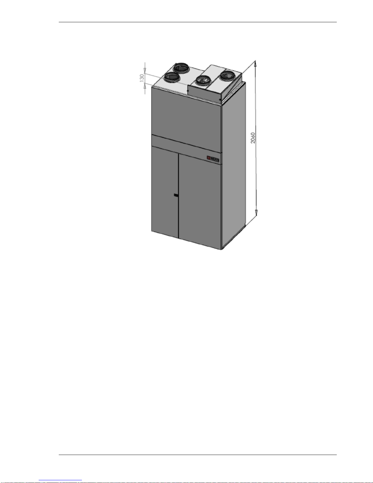
Figur 3: Sketch of Compact P......................................................................................................... 7
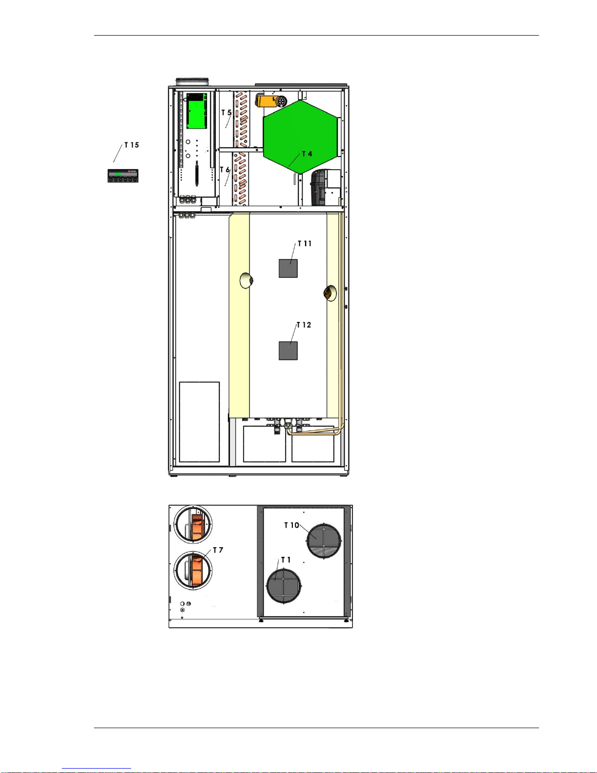
Figur 4: Location of temperature sensors ....................................................................................... 8
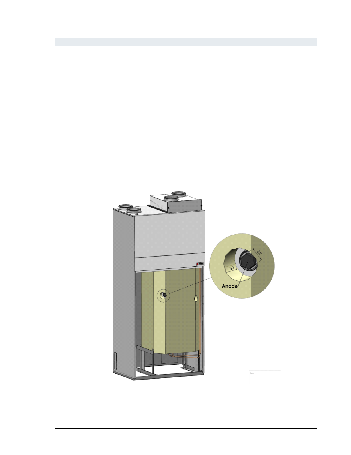
Figur 5: Location of sacrificial anode............................................................................................. 10
Figur 6: Water connections............................................................................................................11
Figur 7: Insulation of ducting......................................................................................................... 12
Figur 8: Headlines in the service menu......................................................................................... 15
Figur 9: The "inlet heating" Menu.................................................................................................. 16
Figur 10: The "Hotwater" Menu..................................................................................................... 17
Figur 11: The "Air quality" Menu.................................................................................................... 18
Figur 12: The "Air exchange" Menu.............................................................................................. 19
Figur 13: The "Defrost" Menu ....................................................................................................... 20
Figur 14: The "Temp. control" Menu.............................................................................................. 21
Figur 15: The "Inlet control" Menu................................................................................................. 22
Figur 16: The "Room control" Menu.............................................................................................. 23
Figur 17: The "Restart" Menu ....................................................................................................... 24
Figur 18: The "Preset" Menu......................................................................................................... 25
Figur 19: The "Manual" Menu ....................................................................................................... 26
Figur 20:Air Filter change............................................................................................................. 28
Figur 21: Safety Switch................................................................................................................. 29

Installation Instructions Compact P
Subject to alterations NILAN A/S Page 3 of 31
Figur 22: Accessories/spare parts................................................................................................. 31

Installation Instructions Compact P
Subject to alterations NILAN A/S Page 4 of 31
Before starting
Please check that the following documents have been supplied with the unit:
- Installation instructions (this manual)
- Operating instructions for CTS602 controls
- Wiring diagram
- Warranty documents
Although we have done everything in our power to write this manual in as clear and concise a way
as possible, please do not hesitate to contact us if you have difficulty understanding it or encounter
problems when installing the system.
NILAN A/S
NILANVEJ 2
DK-8722 Hedensted
(+45) 7675 2500
Compact P is a heat recovery ventilation system with a capacity of up to 330m3/h at 100Pa exter-
nal counter pressure. The energy of the exhaust air is transferred via a heat pump to a 180litres
hot water tank as first priority and to the inlet air as second priority.
The system can be equipped with G3 duct filter. Other optional extras are also available, including
hygrostat and pollen filter unit.
The system is operated via NILAN CTS602 controls offering a wide range of functions, including
menu-based operation, weekly programming, timed filter alarm, fan speed adjustment, etc. The
NILAN CTS602 controls are described in a separate manual supplied together with the system.
For details of spare parts and accessories under Figure 22 “accessories”
Compact P is supplied in a white Aluzink cabinet, fully tested and ready to operate. Installation and
start-up must only be performed by a qualified electrician.

Installation Instructions Compact P
Subject to alterations NILAN A/S Page 5 of 31
Electrical connection
All wiring (power supply, safety circuit breaker, etc.) must only be fitted by a qualified
electrician.
The system must be connected in accordance with the accompanying wiring diagram.
The system is supplied with a 1 m test cable for the CTS602 control panel. The control panel must
be connected to the CTS602 controls using twisted pair cable type 2x2x0.25mm2(max. length
50m).
The CTS602 control panel should be installed in a dry, frost-free location. A temperature sensor
built into the control panel prevents further cooling of the building should the primary heating sys-
tem fail by switching the ventilation system off if control panel temperature falls below a preset
level.
Figur 1: CTS 602 Control Panel

Installation Instructions Compact P
Subject to alterations NILAN A/S Page 6 of 31
Installing Compact P
When installing the unit, it is important to take future service and maintenance into ac-
count. There should be a minimum clearance of 602mm in front of the unit, measured
from the Compact P front panel.
When lifting the unit with straps it is important that the straps has an angle of maximum
45°C off perpendicular.
Individual connectors have been marked out at the factory to facilitate installation. Please note the
attached labels. The connectors should be connected to the duct system using flexible adapters
(flex tube, soundproofed flex tube or similar).
Figur 2: Duct Connections
2. Ø160
Afkastluft
Fortluft
Discharge air
Air extrait
3. Ø160
Fraluft
Abluft
Exhaust air
Air repris
3. Ø160
Tilluft
Zuluft
Inlet air
Air pulsè
1. Ø160
Udeluft
Aussenluft
Fresh air
Air frais

Installation Instructions Compact P
Subject to alterations NILAN A/S Page 7 of 31
Figur 3: Sketch of Compact P
The unit must be installed and leveled on a firm, vibration-free surface. There should be at least
10mm clearance to walls or other permanent installations. Although the unit itself is practically
noise and vibration free, care must be taken to prevent any vibration from being propagated to ad-
joining parts of the building.
The rear angular slide bar of the base frame of the Compact P can be removed in order to make it
possible to push the unit towards the wall to hide water connections etc.
It is important that the condensation outlet of the Compact P be connected to a drain. The unit is
supplied complete with water trap. The outlet should be led frost-free with steady decline to the
nearest drain. The safety valve overflow must also be led to a drain.
If Compact P is enclosed by any covering, it must be possible to remove the covering easily.

Installation Instructions Compact P
Subject to alterations NILAN A/S Page 8 of 31
Figur 4: Location of temperature sensors
Explanation temperature sensors:
T1: Fresh air.
T4: In the counter flow heat exchanger.
T5: Condenser.
T6: Evaporator.
T7: Inlet air after the electrical heating sur-
face.
T10: Exhaust.
T11: Top of the hot water tank.
T12: bottom of the hot water tank.
T15: CTS602 panel.
temperatures are shown in the ”Show data”
menu”.
E5: Heating element 1,5kW

Installation Instructions Compact P
Subject to alterations NILAN A/S Page 9 of 31
Condensation drain/water trap
Compact P is supplied with 20mm condensation outlet (PVC, GF fittings). The unit is also equipped
with built-in water trap.
The condensation outlet must be led frost-free with a steady decline of at least 1 cm/m to
the nearest drain. The safety valve overflow must also be led to a drain.
In order to prevent ice formation, it may be necessary to equip the condensation outlet
with a heating cable where frost is possible Protecting the condensation outlet from frost
is the responsibility of the fitter.

Installation Instructions Compact P
Subject to alterations NILAN A/S Page 10 of 31
Water connection
The inner tank surface is enamelled and the tank is equipped with a sacrificial anode.
All connectors have 3/4” threads, with the exception of the anode access which is a 5/4” sleeve.
All water pipes are connected to the bottom of the unit.
If required, hot water circulation can be established by fitting a non-return valve to the recirculation
connector of the tank after inserting a 80cm long circulation pipe (optional accessory) into the tank.
See figure 3 below.
If hot water circulation is not required, the connector and fitted blanking plug should be left un-
touched.
Hot water circulation may result in considerable heat loss within the piping system. A large propor-
tion of heat pump output may therefore be lost. To prevent heat loss, circulation and hot water
pipes must be insulated with at least 30mm of mineral wool or other type of pipe insulating materi-
al.
Figur 5: Location of sacrificial anode

Installation Instructions Compact P
Subject to alterations NILAN A/S Page 11 of 31
Figur 6: Water connections
Supplementary coil is standard only in the VP 18 Compact Sol unit type.
1. Tilslutning for cirkulationsrør ¾”
Anschluss für zirkulationrohr ¾”
Circulation pipe connection ¾”
Branchement à tuyeau de circulation ¾”
2. Fremløb suppleringsspiral ¾”
Vorlauf WT ¾”
Inlet supplementary coil ¾”
Alimenration échangeur supplémentaire ¾”
3. Varmtvandsudtag ¾”
Warm Wasser ¾”
Hot water connection ¾”
Sortie eau chaude ¾”
4. Koldt vandsindtag ¾”
Kalt wasser ¾”
Cold water connection ¾”
Alimentation eau froide ¾”
5. Retur suppleringsspiral ¾”
Rücklauf WT ¾”
Return supplementary coil ¾”
Retour échangeur supplémentaire¾”

Installation Instructions Compact P
Subject to alterations NILAN A/S Page 12 of 31
Duct connection
Ducting and fittings with rubber seals of tightness class B are recommended. It is also advisable
that all duct connections to Compact P be made with approx. 1m of soundproofed flex tube in order
to dampen sound emission.
Ducting should be cut to length using a hacksaw or angle grinder and laid in accordance with the
design drawing. Ducting is usually either attached to rafter feet using perforated strip or suspended
in fitting strip. Avoid pinching the ducting in any way and any unnecessary bends.
The ducting must be insulated. Sometimes, standard loft insulation can be used for the purpose.
All ducting should be insulated with 100mm mineral wool to prevent heat loss and condensation.
Such insulation requirements also apply to soundproofed flex tubing. It is recommended that two
layers of 50mm insulating material be used. If ducting is installed in an unheated room, it is inad-
visable to switch the system off for prolonged periods as air from heated rooms will rise into the
ducting and condensate, thus possibly causing moisture problems.
Figur 7: Insulation of ducting
The discharge duct leads the exhaust air (from which the system has recovered the energy it con-
tained) to the outside through the roof or outer wall. It is important that the roof stack or wall grille
has at least the same area as the duct immediately ahead of the stack or grille. Any contraction will
cause unnecessary pressure drop, which may reduce ventilation capacity.
Holes for inlet and exhaust valves should be cut to fit the frame of the valve concerned. Secure the
valve frame in position using screws and then attach the valve. Where the valves should be posi-
tioned depends on room design and use. It is, for example, inadvisable to install inlet valves
immediately above where people usually sit as inlet air may sometimes be perceived as a draught.
Loft insulation
material
Duct
Granulate

Installation Instructions Compact P
Subject to alterations NILAN A/S Page 13 of 31
Supplementary heating element DHW
The hot water tank has a supplementary heating element of 1,5kW. The heating element can be
activated and de-activated via the CTS602 control, see the “Hotwater” menu.
The temperature, at which the heating element should be active (T11), can be set in the “Hotwater”
menu, see “Directions for use of the CTS602 control

Installation Instructions Compact P
Subject to alterations NILAN A/S Page 14 of 31
Start-up and configuration of CTS602 controls
Startup
Once all connections have been checked, check that the tank is full of water. To do so, open the
hot water tap.
Open ceiling valves, ensuring that valve cone is level with front edge.
CTS602 configuration
This section describes the SERVICE menu of the CTS602 controls. For instructions on everyday
operation of the CTS602 controls, please refer to the accompanying CTS602 operating instruc-
tions.
On the CTS602 control panel, press:
- ESC to return to the previous menu
- qp to scroll upwards or downwards through the menus or to
adjust the setting of an activated menu option
- ENTER to activate a menu option
- ENTER to confirm a menu option setting
- OFF switch off the controls
- ON to switch on the controls

Installation Instructions Compact P
Subject to alterations NILAN A/S Page 15 of 31
Activating the SERVICE menu
Press and hold qand ENTER simultaneously for 10 seconds. The SERVICE menu can then be
accessed. Press qrepeatedly until SERVICE appears on the display. Press ENTER to activate
the SERVICE menu. It is then possible to scroll through the SERVICE menu options using the pq
buttons. The options available on the SERVICE menu are shown in the figure below.
DEFROST
ENTER
SERVICE
AIR
QUALITY
AIR
EXCHANGE
TEMP.
CONTROL
INLET
CONTROL
ROOM
CONTROL
RESTART
OFF
PRESET
OFF
MANUAL
OFF
page 16
page 17
page 18
page 19
page 20
page 21
page 22
page 23
page 24
INLET
HEATING page 15
HOTWATER
page 25
Figur 8: Headlines in the service menu

Installation Instructions Compact P
Subject to alterations NILAN A/S Page 16 of 31
Inlet heating
In the ”Inlet heating” menu it is possible to activate and de-activate the heating surface in the inlet
air and to set the regulation time.
On the CTS602 control panel, press:
- ESC to return to the previous menu
- qp to scroll upwards or downwards through the menus or to
adjust the setting of an activated menu option
- ENTER to activate a menu option
- ENTER to confirm a menu option setting
- OFF switch off the controls
- ON to switch on the controls
HOTWATER
DEFROST
SELECT
ON ENTERENTER
SELECT
”OFF”
INTEGRAL
TIME 10
AIR
EXCHANGE
INLET
CONTROL
SERVICE ENTER
TEMP.
CONTROL
RESTART
OFF
MANUAL
OFF
PRESET
OFF
ROOM
CONTROL
AIR
QUALITY
INLET
HEATING
Regulation time
in minutes.
SELECT
”ON”
INTEGRAL
TIME ”10"
Figur 9: The "inlet heating" Menu

Installation Instructions Compact P
Subject to alterations NILAN A/S Page 17 of 31
Hotwater
The ”Hotwater” menu enables you to activate and de-activate the electrical heating element in the
hot water tank.
When the heating element is set to ON, a ”w” will occur in the main menu, when the heating ele-
ment is in use.
AUTO W
”>2<” 19° C
Options that flash are indicated by ” ”
On the CTS602 control panel, press:
- ESC to return to the previous menu
- qp to scroll upwards or downwards through the menus or to
adjust the setting of an activated menu option
- ENTER to activate a menu option
- ENTER to confirm a menu option setting
- OFF switch off the controls
- ON to switch on the controls
HOTWATER ENTER EL SUP
ON EL SUP
”ON”
LEGIONEL
”MON”
ENTER
ENTER
ENTER
ENTER
ENTER
EL SUP
”OFF”
LEGIONEL
OFF
LEGIONEL
”OFF”
A weekday can
be chosen,
where the
hotwater will be
warmed up to
65°C between
01.00 and 06.00
o’clock.
The legionella
fuction is not
active.
SERVICE ENTER
DEFROST
INLET
CONTROL
TEMP.
CONTROL
PRESET
OFF
RESTART
OFF
ROOM
CONTROL
AIR
EXCHANGE
INLET
HEATING
AIR
QUALITY
PRIORITY
”5"°C
Temperature for prioritizing the
hot water. (All energy in the
exhaust air is delievered to the
hot water). The setting is
suptracted to T12(the temperature
in the bottom of the hot water
tank).
MANUAL
OFF
PRIORITY
”5"°C ENTER
Figur 10: The "Hotwater" Menu

Installation Instructions Compact P
Subject to alterations NILAN A/S Page 18 of 31
Air quality
In the ”Air quality” menu it is possible to choose between 3 types of regulation: Humidity, Humidity
+ CO2or OFF.
On the CTS602 control panel, press:
- ESC to return to the previous menu
- qp to scroll upwards or downwards through the menus or to
adjust the setting of an activated menu option
- ENTER to activate a menu option
- ENTER to confirm a menu option setting
- OFF switch off the controls
- ON to switch on the controls
HOTWATER
DEFROST
FUNCTION
OFF ENTERENTER FUNCTION
”OFF”
AIR
EXCHANGE
INLET
CONTROL
SERVICE ENTER
TEMP.
CONTROL
RESTART
OFF
MANUAL
OFF
PRESET
OFF
ROOM
CONTROL
AIR
QUALITY
INLET
HEATING
Can be set to:
OFF, HUMIDITY or
HUM+CO2, when is
mounted.
Figur 11: The "Air quality" Menu

Installation Instructions Compact P
Subject to alterations NILAN A/S Page 19 of 31
Air exchange
The AIR EXCHANGE menu allows four ventilation steps (air quantities) to be set. Individual values
for inlet and exhaust can be set for each ventilation step.
A minimum ventilation step for inlet air and minimum and maximum steps for exhaust air can also
be set.
On the CTS602 control panel, press:
- ESC to return to the previous menu
- qp to scroll upwards or downwards through the menus or to
adjust the setting of an activated menu option
- ENTER to activate a menu option
- ENTER to confirm a menu option setting
- OFF switch off the controls
- ON to switch on the controls
INLET
HEATING
AIR
EXCHANGE ENTER
SERVICE ENTER
DEFROST
INLET
CONTROL
TEMP.
CONTROL
PRESET
OFF
RESTART
OFF
ROOM
CONTROL
HOTWATER
AIR
QUALITY
The lowest permissible
ventilation step for fresh air/inlet
(0-2)
The lowest permissible
ventilation step for outlet/exhaust
(1-2)
INLET
MIN 0
EXHAUST
MIN 1
EXHAUST
MAX 4
The highest permissible
ventilation step for outlet/exhaust
(3-4)
INLET25%
INLET
>2< 45%
INLET
>3< 70%
EXHAUST
>1< 25%
EXHAUST
>3< 70%
EXHAUST
>4< 100%
INLET
>4< 100%
EXHAUST
>2< 45%
Each ventilation step can be set
as a percentage of maximum fan
speed.
MANUAL
OFF
>1<
.
.
Figur 12: The "Air exchange" Menu

Installation Instructions Compact P
Subject to alterations NILAN A/S Page 20 of 31
Defrost
The DEFROST menu determines the mode of system operation while the evaporator surface and
the counter flow heat exchanger in the exhaust air flow is being defrosted.
Options that flash are indicated by ” ”
On the CTS602 control panel, press:
- ESC to return to the previous menu
- qp to scroll upwards or downwards through the menus or to
adjust the setting of an activated menu option
- ENTER to activate a menu option
- ENTER to confirm a menu option setting
- OFF switch off the controls
- ON to switch on the controls
INLET
HEATING
Lockout between 2
defrost periods. Can
be set from 15 –
720 minuttes.
DEFROST PERIOD
60 MIN
ENTER
HOTWATER
AIR
EXCHANGE
INLET
CONTROL
SERVICE ENTER
TEMP.
CONTROL
RESTART
OFF
MANUAL
OFF
PRESET
OFF
ROOM
CONTROL Max. defrosting
time of heat
exchanger.
AIR
QUALITY
TERMINAT
T4 4°C
COMP MAX
5 MIN
EXCH MAX
25 MIN
Max. defrosting
time of
compressor.
Adjustable temperature,
which terminates
defrosting of heat
exchanger. Temperature
measured at sensor T4.
Figur 13: The "Defrost" Menu
Other manuals for Compact P
9
Table of contents
Other nilan Ventilation manuals