Delta GBR80MHLED User manual

MODELS:
GBR80HLED,
GBR
80
LED,
GBR80MHLED
,
GBR100HLED
,
GBR
100
LED
INSTALLATION AND OPERATING INSTRUCTIONS
VENTILATION FAN /DIMMABLE LED LIGHT
READ AND SAVE THESE INSTRUCTIONS
GENERAL SAFETY INFORMATION
1.
Make sure that the electric service supply v ltage is AC 120V,
60Hz.
2.
F ll w all l cal electrical and safety c des, as well as the Nati n
Electrical C de (NEC) and the Occupati n Safety and Healthy Act
(OSH Act).
3.
Always disc nnect the p wer s urce bef re w rking n r near
the ventilating fan, m t r r juncti n b x.
4.
Pr tect the p wer c rd fr m sharp edges, il, grease, h t
surfaces, chemicals r ther bjects.
5.
D n t kink the p wer c rd.
6.
D n t install the unit where ducts are c nfigured as sh wn in
Fig. A.
7.
Pr vide sucti n parts with pr per ventilati n.
8.
This unit is UL listed f r use ver a bathtub r sh wer when
installed in a GFCI pr tected branch circuit.
WARNING
TO REDUCE THE RISK OF FIRE, ELECTRIC SHOCK, OR
INJURY TO PERSONS, OBSERVE THE FOLLOWING:
1. Use this unit nly in the manner intended by the manufacturer.
If y u have questi ns, c ntact the manufacturer.
2. Bef re servicing r cleaning unit, switch p wer ff at service
panel and l ck the service disc nnecting means t prevent
p wer fr m being switched n accidentally. When the service
disc nnecting means cann t be l cked, securely fasten a
pr minent warning device, such as a tag, t the service panel.
3. Installati n w rk and electrical wiring must be d ne by qualified
pers n(s) in acc rdance with all applicable c des and standards,
including fire-rated c nstructi n.
4. Sufficient air is needed f r pr per c mbusti n and exhausting f
gases thr ugh the flue (chimney) f fuel burning equipment t
prevent back drafting. F ll w the heating equipment
manufacturer’s guideline and safety standards such as th se
published by the Nati nal Fire Pr tecti n Ass ciati n (NFPA),
and the American S ciety f Heating, Refrigerating and Air-
C nditi ning Engineers (ASHRAE), and the l cal c de auth rities.
5. When cutting r drilling int wall r ceiling, d n t damage
electrical wiring and ther hidden utilities.
6. Ducted fans must always be vented t the utd rs.
7. If this unit is t be installed ver a tub r sh wer, it must be
marked as appr priate f r the applicati n and be c nnected t a
GFCI (Gr und Fault Circuit Interrupter) --- pr tected branch
circuit.
8. D n t use this unit with any ther s lid-state c ntr l devices.
S lid-state c ntr l devices may cause harm nic dist rti n,
which can cause a m t r humming n ise. (Avertissement: ne
c nvient pas à des régulateurs de vitesse à semi-c nducteurs).
9. NEVER place a switch where it can be reached fr m a tub r
sh wer.
10. N t t be installed in a ceiling thermally insulated t a value
greater than R50. (This is required f r installati n in Canada
nly).
Turning angle too large Duct shrink
Too many elbows Elbow near the body
Body
Fig. A
CAUTION
1. F r General Ventilating Use Only. D N t Use T Exhaust
Hazard us Or Expl sive Materials And Vap rs.
2. N t f r use in c king areas. (Fig. B)
3. This pr duct must pr perly c nnect t the gr unding c nduct r
f the supply circuit.
4. T reduce the risk f injury t pers ns, install the fan at least 8.2
feet (2.5m) ab ve the fl r.
45
Cooking area
45
Do not install above or
inside this area
Cooking
Equipment floor
Fig. B
Page 1.

MODELS:
GBR80HLED,
GBR
80
LED,
GBR80MHLED
,
GBR100HLED
,
GBR
100
LED
SUPPLIED ACCESSORIES
Part name Appearance Quantity
Grille
1
Fan
1
H using
1
Duct C nnect r
(4’’)
1
L ng W d Screw
(ø4×25)
8
Machine Screw
(#8-32x5/16’’)
4
Suspensi n Bracket
4
INSTALLATIONS
Pr per insulati n ar und the fan t minimize building heat l ss and
gain. 4’’ circular duct is rec mmended f r installati n. The ducting
fr m this fan t the utside f the building has a str ng effect n
the air fl w, n ise and energy use f the fan. Use the sh rtest,
straightest duct r uting p ssible f r best perf rmance, and av id
installing the fan with smaller ducts than rec mmended. Insulati n
ar und the ducts can reduce energy l ss and inhibit m ld gr wth.
Fans installed with existing ducts may n t achieve their rated air
fl w.
Roof cap
(with built-in damper)
Seal gap
around
housing
Caulk termination
to duct
Fan housing
Short piece of flexible
duct helps alignment
and absorbs sound
Wall cap
(with built-in damper)
or
MOUNT
MOUNTMOUNT
MOUNT
HOUSING
HOUSINGHOUSING
HOUSING
WITH
WITHWITH
WITH
FLANGE:
FLANGE:FLANGE:
FLANGE:
1. T bend the h using tabs ut t 90 degree and make
h using tabs c ntact the b tt m f the j ist.
Joist
Tabs
2. The h using m unts with 4 l ng w d screw (Ø4×25).
Screw h using t j ist thr ugh l west h les in each
m unting flange, then thr ugh the ther h les.
Joist
Long Wood Screw
( 4×25)
USING SUSPENSION BRACKETS
USING SUSPENSION BRACKETS USING SUSPENSION BRACKETS
USING SUSPENSION BRACKETS
3. Sliding suspensi n brackets available t all w f r y ur
specific
p siti ning f h using anywhere between j ists
and span up t 24’’.
Suspension Bracket
4. Extend suspensi n brackets t the width f the j ists. Make
sure the fan b dy is level and perpendicular with the j ist.
5. Secure suspensi n brackets t j ists with l ng w d screw
(ø4×25).
6. Secure suspensi n brackets t gether with machine screw
(#8-32x5/16’’).
(#8-32x5/16”)
Joist
Joist
Page 2.

MODELS:
GBR80HLED,
GBR
80
LED,
GBR80MHLED
,
GBR100HLED
,
GBR
100
LED
DUCT CONNECTION
1. Insert the duct int the duct c nnect r and tape all ductw rk
c nnecti ns t make them secure and air tight.
2. Install the duct with a gradient 1°~2° t the utside.
Inside Outside
Duct
Body
Gradient
1°~2°
Tape
Ceiling
Grille
Duct Connector
CONNECT WIRING
1. F ll w all l cal electrical and safety c des, ANSI/NFPA70.
2. NEVER place a switch where it can be reached fr m a tub r
sh wer.
3. C nnect wires as sh wn in wiring diagrams.
F r M dels: GBR80LED, GBR80MHLED, GBR100LED
POWER SWITCH
LIGHT SWITCH
JUNCTION BOX SWITCH BOX
WHITE
BLACK
OFF
ON
WHITE
RED
GREEN
GRD
L
N
L
N
OFF
ON
ON/OFF SWITCH
(purchase separately) SWITCH BOX
120 VAC
LINE IN
WIRING
PLATE
BLACK
WHITEGROUND
(bare)
RED
LIGHT
SWITCH
POWER
SWITCH
F r M dels: GBR80HLED, GBR100HLED
HI
POWER SWITCH
MODE SWITCH
JUNCTION BOX SWITCH BOX
WHITE
BLACK
OFF
ON
BLUE
GREEN
GRD
L
N
L
N
ON
LIGHT SWITCH
RED
L
N
WHITE
WHITE
BLACK
ON/OFF SWITCH
(purchase separately) SWITCH BOX
120 VAC
LINE IN
WHITE
GROUND
(bare)
POWER
SWITCH
WIRING
PLATE
MODE
SWITCH
LIGHT
SWITCH
RED
BLUE
4. Using wire nuts (n t pr vided), c nnect h use p wer cable
t ventilating fan.
5. 14 AWG (2.1 mm
2
) is the smallest c nduct r that shall be
used f r branch-circuit wiring.
GRILLE ATTACHMENT & TEST RUN
1. Insert the LED lighting c nnect r int the p wer s cket f
main b dy as bel w sh wn.
2. Insert the m ti n plug c nnect r int the h using. (f r
GBR80MHLED nly)
3. Insert the m unting springs int the sl ts and m unt the
grille t the fan unit.
Spring
Grille
Lighting Connector
Slots
4. When the p wer n, check f r abn rmal vibrati n r s und.
OPERATION
1. F r Single Speed M dels: GBR80LED, GBR100LED
1-1. Turn n the p wer switch t perate ON r OFF, and LED
indicat r is green.
2. F r Humidity m dels: GBR80HLED, GBR80MHLED, GBR100HLED
Humidity t lerance is ab ut ±10%. L ng -time perati n will
influence the detecting precisi n as dust accumulates. The
humidity switch may need t be adjusted.
80 SERIES
0
50
CFM
50
80
70
60
%RH
0
60
50
80
70
60
%RH
100 SERIES
Low speed air volume
preset control
Humidity preset control
Low Speed
CFM
Low Speed
2-1. Humidity c ntr l m de: Turn the POWER switch n t
perate at humidity c ntr l m de - the LED indicat r
will be blue. When the ambient humidity is higher than
the user-adjustable set-p int, the fan will run at full
speed. When the ambient humidity is l wer than the
set-p int, the fan will c ntinue t run at the full speed
until a 10-minute time delay has elapsed, and then will
aut matically change t the user -adjustable l w speed
airfl w.
Page 3.

MODELS:
GBR80HLED,
GBR
80
LED,
GBR80MHLED
,
GBR100HLED
,
GBR
100
LED
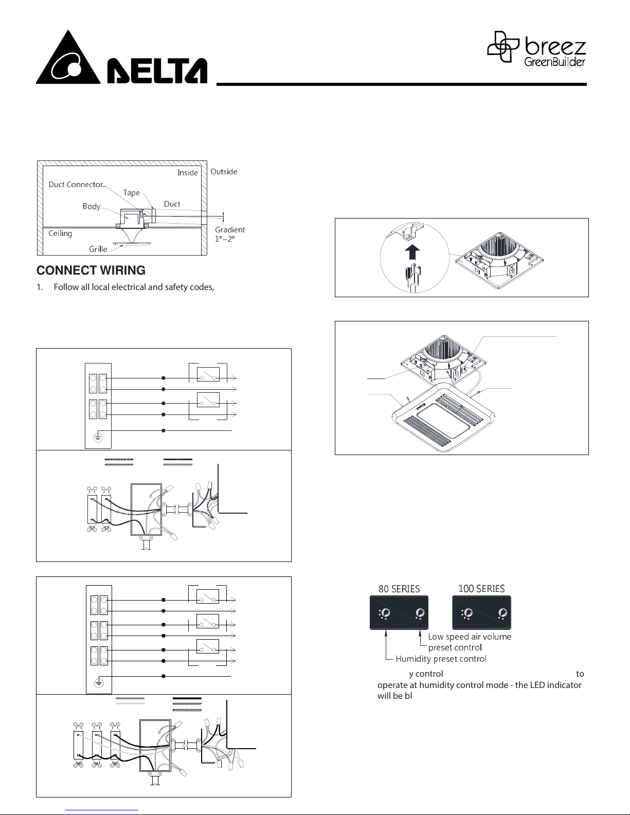
2-2. Full speed m de: Turn the MODE switch n t perate at
full speed m de - the LED indicat r will be amber.
(f r GBR80HLED and GBR100HLED nly)
2-3. When m ti n is detected, the fan will run at full speed
and the LED indicat r will be amber. When m ti n is n t
detected, the fan will c ntinue t run at the full speed
until a 10-minute time delay has elapsed, and then will
aut matically change t the user -adjustable l w speed
airfl w. (f r GBR80MHLED nly)
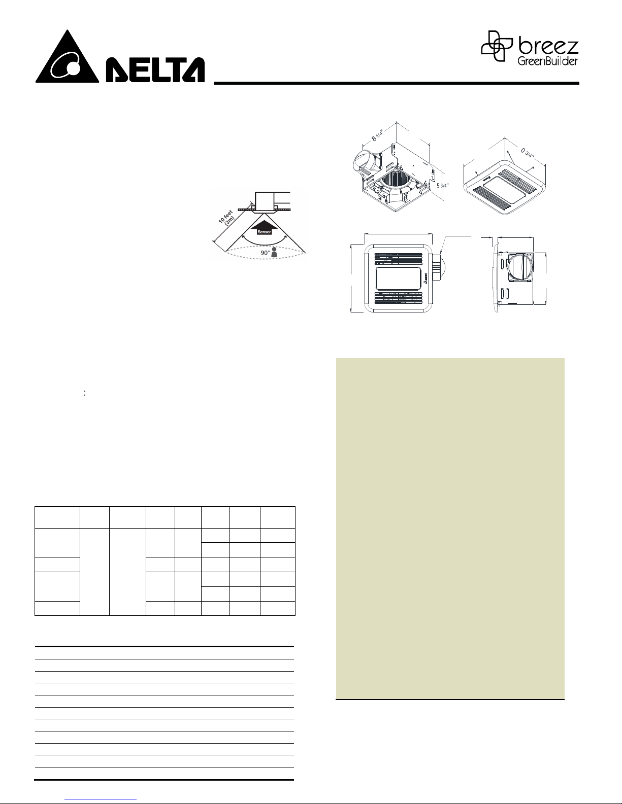
*M ti n sens r detectible range:
The distance that m ti n can be
detected is limited t 10 feet (3m).
The field f view f the sens r is 90°.
(R m temperature is 25°C )
MAINTENANCE
WARNING:
Disc nnect p wer s urce bef re w rking n unit. R utine
maintenance must be d ne every year.
CAUTION:
1. Never use gas line, benzene, thinner r any ther such
chemicals f r cleaning the ventilating fan.
2. D n t all w water t enter m t r.
3. D n t s ak resin parts in water ver 140°F (60°C).
CLEANING
:
1. Wash and clean grille. CAUTION: D n t let water int the lamp
base. (Use n n-abrasive kitchen detergent, wipe dry with a new
cl th.)
2. Using a cl th dampened with n n-abrasive kitchen
detergent, rem ve dust and dirt fr m ventilating fan. Wipe
dry with new cl th.
3. Replace grille.
SPECIFICATIONS – FAN
Model No. Voltage
(V)
Frequency
(Hz)
Weight
(lb.)
Power
Max.
(W)
Power
@ .1SP
(W)
Air Flow
@ .1SP
(W)
Remark
GBR8 HLED,
GBR8 MHLED
12 6
6.1 13
11. 8
Full
speed
4.4 5
Low
speed
GBR8 LED 6. 13 11. 8
Single
speed
GBR1 HLED 6.3 14
13.6 1
Full
speed
4.8 6
Low
speed
GBR1 LED 6.2 14 13.6 1
Single
speed
N te: Design and specificati ns subject t change with ut n tice.
SPECIFICATIONS – LED LIGHT
ITEM SPEC
VOLTAGE ( V ) 12
FREQUENCY ( Hz ) 6
POWER CONSUMPTION ( W ) 13
LUMINOUS FLUX ( Lumen ) 85
CORRELATED COLOR TEMPERATURE ( Kelvin ) 27
DIMMABLE YES
FCC QUALIFIED YES
ENERGY STAR QUALIFIED YES
ROHS QUALIFIED YES
SAFETY CERTIFICATIONS UL/cUL
DIMENSIONS
8
1/4
"
10
3/4
"
10
3/4
"
8"
4" Duct
10
3/4
"
10
3/4
" 8
1/4
"
5
3/4
"
7/8
"
WARRANTY
DELTA ELECTRONICS TH
REE YEAR LIMITED WAR
RANTY
Delta Electronics Inc. (“Delta Electronics”) warrants to the original
consumer purchaser in the USA and Canada that the Breez
ventilation fan products will be free from defects in material or
workmanship. This warranty is limited to three (3) years from the
original date of purchase.
Limitations and Exclusions
1. During the warranty period, a replacement for any defective
product will be supplied free of charge for installation by the
consumer. The warranty provided herein does not cover
charges for labor or other costs incurred in the
troubleshooting, repair, removal, and installation service.
2. All returns of defective parts or products must include the
product model number, and must be made through an
authorized Delta Electronics distributor. Authorized returns
must be shipped prepaid. Repaired or replacement products
will be shipped by Delta Electronics F.O.B. shipping point.
3. Delta Electronics shall not be liable for any indirect, incidental,
consequential, punitive, or special damages arising out of or in
connection with products use or performance, regardless of
the form of action whether in contract, tort (including
negligence), strict product liability or otherwise.
4. This warranty does not extend to fluorescent lamp starters and
tubes.
5. The warranty does not cover if user does not comply with
manufacture’s installation manual.
6. To qualify for warranty service, you must notify Delta
Electronics at the address or telephone number below.
7. Delta Electronics shall have no liability to the original owner-
user with respect to any defect caused by abuse, misuse,
neglect, improper transportation or storage, improper testing,
improper installation, improper operation, improper use,
improper maintenance, improper repair, improper alteration,
improper modification, tampering or accident of products or
parts thereof, or unusual deterioration or degradation of
products or parts thereof due to a physical environment
beyond the requirements of products’ specifications.
Address: 461 1 Fremont Boulevard, Fremont, CA 94538
US Toll Free Number: 1
-
888
-
979
-
9889
Page 4.
5 162211
This manual suits for next models
4
Other Delta Ventilation manuals