Fantech 405335 User manual

Heat Recovery Ventilator
Installation Manual
Fantech reserves the right to modify, at any time and
without notice, any or all of its products’ features,
designs, components and specifications to maintain
their technological leadership position.
Item #: 405335
Rev Date: 110512
United States
10048 Industrial Blvd.
Lenexa, KS 66215
Phone: 800-747-1762; 913-752-6000
Fax: 800-487-9915; 913-752-6466
Canada
50 Kanalflakt Way,
Bouctouche, NB E4S 3M5
Phone: 800.565.3548; 506.743.9500
Fax: 877.747.8116; 506.743.9600
www.fantech.net; [email protected]

2
Note Important
note Information Technical
information Practical tip
PLEASE READ THIS MANUAL BEFORE INSTALLING UNIT
For residential use only
Before installation careful consideration must be given to how this system will operate if connected to
any other piece of mechanical equipment, i.e. a forced air furnace or air handler operating at a higher
staticpressure.Afterinstallation,thecompatibilityofthetwopiecesofequipmentmustbeconrmedby
measuringtheairowoftheHeatRecoveryVentilatorusingthebalancingprocedurefoundinthismanual.
It is always important to assess how the operation of any HRV may interact with vented combustion
equipment (i.e. Gas Furnaces, Oil Furnaces, Wood Stoves, etc.)
Products are designed and manufactured to provide reliable performance, but they are not guaran-
teed to be 100% free of defects. Even reliable products will experience occasional failures, and this
possibility should be recognized by the user. If these products are used in a life support ventilation
system where failure could result in loss or injury, the user should provide adequate back-up ven-
tilation, supplementary natural ventilation or failure alarm system, or acknowledge willingness to
accept the risk of such loss or injury.
Your ventilation system should be installed in accordance with the local building code that is in
effect, in absence of such requirements, it is recommenced to check with local authorities having
jurisdiction in your area prior to installing this product.

3
TABLE OF CONTENTS
DETERMINING YOUR AIRFLOW REQUIREMENT ..................................................... 4
INSTALLATION EXAMPLES
Fully dedicated system ................................................................ 5
Partially dedicated system .............................................................. 6
Simplified Installation ................................................................. 7
EXTERIOR DUCTING INSTALLATION
Weatherhood Location ..................................................................... 9
Installing the ducting to the weatherhood ....................................................... 9
INTERIOR DUCTING INSTALLATION
General Tips ............................................................................ 9
Installing duct to HRV ..................................................................... 9
Supply & Exhaust Air Grilles Location........................................................... 9
HRV INSTALLATION ........................................................................ 10
AIRFLOW ADJUSTMENT & BALANCING
General preparation ..................................................................... 11
Adjusting airflow using integrated balancing system ............................................... 11
Balancing steps ........................................................................ 12
LOW VOLTAGE CONTROL SYSTEMS ............................................................. 13
WIRING DIAGRAM ......................................................................... 14

4
Room classification Number of rooms CFM (L/s)
CFM Required
Master bedroom x 10 L/s (20 CFM) =
Basement yes or no =
Bedrooms x 5 L/s (10 CFM) =
Living room x 5 L/s (10 CFM) =
Others x 5 L/s (10 CFM) =
Kitchen x 5 L/s (10 CFM) =
Bathroom x 5 L/s (10 CFM) =
Laundry room x 5 L/s (10 CFM) =
Utility room x 5 L/s (10 CFM) =
Total Ventilation Requirements (add last column ) =
if yes add 10 L/s (20 CFM)
if no = 0
1 CFM = 0.47 L/s
1 L/s = 2.13 CFM
Room Count Method
DETERMINING YOUR AIRFLOW REQUIREMENT
ASHRAE method
Ventilation Air requirements
Floor area Bedrooms
0-1 2-3 4-5 6-7 >7
Ft2m2CFM L/s CFM L/s CFM L/s CFM L/s CFM L/s
< 1500 <139 30 14 45 21 60 28 75 35 90 42
1501-3000 139.1-279 45 21 60 28 75 35 90 42 105 50
3001-4500 279.1-418 60 28 75 35 90 45 105 50 120 57
4501-6000 418.1-557 75 35 90 42 105 50 120 57 135 64
6001-7500 557.1-697 90 42 105 50 120 57 135 64 150 71
>7500 >697 105 50 120 57 135 64 150 71 165 78
* ASHRAE 62.2-2010 Table 4.1,
Ventilation and Acceptable Indoor Air Quality in Low-Rise Residential Buildings.
Bathroom: If the HRV is going to provide the required local exhaust ventilation for each bathroom with each a con-
tinuous 20 CFM (10 L/s), this ventilation rate can be considered as part of the whole-building ventilation rate.

5
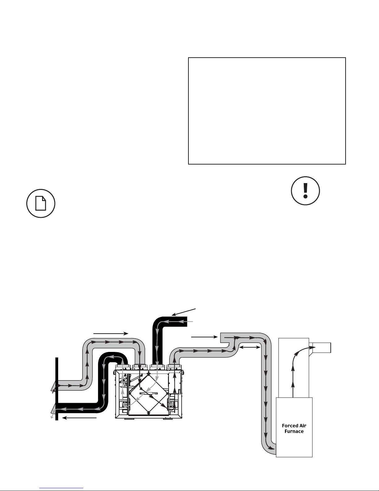
HRV ducting for fully Dedicated System
Stale air from inside
Outside
Fresh air to living areas
Fresh air from
outside
Stale air to
outside
INSTALLATION EXAMPLES
Example only – duct configuration may differ depending on the model.
FULLY DEDICATED SYSTEM
BEST FOR NEW CONSTRUCTION
1. Stale air is drawn from key areas of the home requiring local exhaust
(bathroom, kitchen, laundry room).
2. Fresh air is distributed directly to habitable rooms in the house (bed-
rooms, living room)
3. The HRV’s airflow must be balanced after installation using the procedure
found in the section “AIRFLOW BALANCING”
Suggested installation for:
- Hydronic baseboard
- Inoor heating
- Electric baseboard
- Mini split heat pump
Benets: Provides the best fresh air distribu-
tion in the house; lowest operation cost since
the furnace/air handler unit is not needed.
6
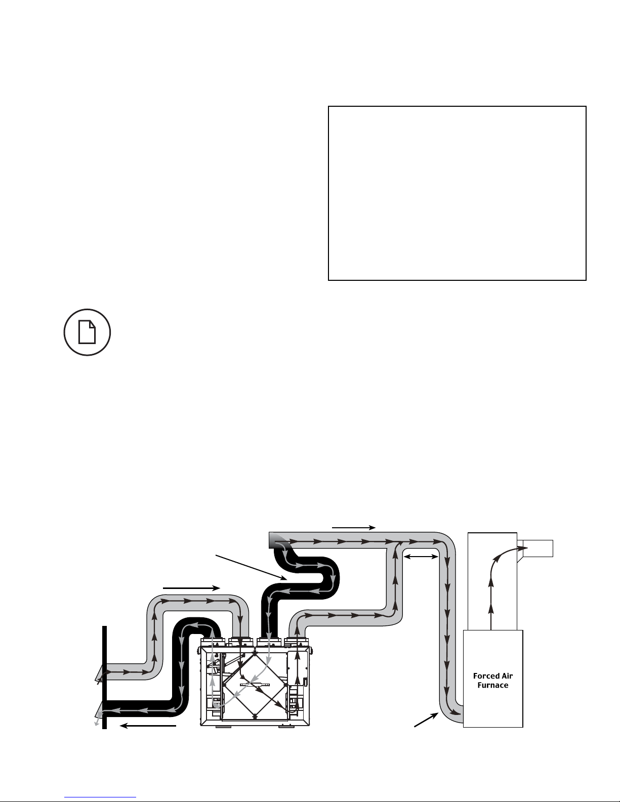
HRV/ Furnace ducting for Partially Dedicated System
INSTALLATION EXAMPLES (CONT'D)
DIRECT CONNECTION of the SUPPLY AIR STREAM to the RETURN PLENUM of the AIR HANDLER (Stale air drawn from key areas of home)
PARTIALLY DEDICATED SYSTEM (BETTER)
Suggested installation for:
- Central furnace (air handling unit or central
air conditioners)
- When ducting fresh air to living area is not
possible or practical, i.e. expensive or when
the central AHU will operate year-round.
Benets: Conditions the fresh air prior to
distributing it throughout the house
1. In order to provide proper distribution of the fresh air, it is recommend-
ed that the furnace blower be set to run continuously or interconnected
with HRV.
2. Stale air is drawn from key areas of the home (bathroom, kitchen, laun-
dry room). (see page 15)
3. Fresh air is supplied to the return air plenum of the furnace.
4. Due to the difference in pressure between the HRV and the equipment it
is being connected to the HRV’s airflow must be balanced on site, using
the procedure found in the section “AIRFLOW BALANCING”
Make sure the HRV is
capable of meeting the
required airow rate.
Stale air from inside
* Unit airflow should be balanced while HRV is on
“High” speed and furnace blower is running.
Outside
Fresh air
to living
areas
1 m (3' 3")
min.
recommended
Return
plenum
Stale air to
outside
Fresh air from
outside
7
Stale air from inside
Outside
Fresh air to
living areas
1 m (3' 3")
min.
recom-
mended
Cold air
return
HRV/ furnace for Simplified Installation – Option 1
INSTALLATION EXAMPLES (CONT'D)
DIRECT CONNECTION of both the HRV SUPPLY AIR STREAM and EXHAUST AIR STREAM to the FURNACE COLD AIR RETURN
SIMPLIFIED INSTALLATION
(GOOD)
(RETURN/RETURN METHOD)
Suggested installation for:
- When bathroom and kitchen already have lo-
cal exhaust system
- May be suitable for retrotting
Benets: Most cost effective installation type
1. Furnace blower must operate when ventilation from HRV is required. The fur-
nace should be set to run continuously or interlocked with HRV. See page 15.
2. A minimum separation of 1m (39’’) is recommended between the two
direct connections.
3. In order to prevent exhausting any fresh air, the HRV’s exhaust air connection
should be upstream of the HRV’s supply air connection when ducting to the
furnace’s cold air return.
4. Due to the difference in pressure between the HRV and the equipment it is
being connected to the HRV’s airflow must be balanced on site, using the
procedure found in the section “AIRFLOW BALANCING”
Stale air to
outside
Fresh air from
outside
* Unit airflow should be balanced while HRV is on
“High” speed and furnace blower is running.

8
EXTERIOR DUCTING INSTALLATION
WEATHERHOOD LOCATION
•Decidewhereyourintakeandexhausthoodswillbelocated.
Locating the Intake Weatherhood
•Shouldbelocatedupstream(ifthereareprevailingwinds)fromthe
exhaust outlet.
•Ataminimumof2m(6’)awayfromdryerventsandfurnaceexhaust
(medium or high efficiency furnaces), driveways, oil fill pipes, gas
meters, or garbage containers.
•Ataminimumheightof460mm(18’’)abovetheground,orabove
the level of expected snow accumulation.
•Ataminimumdistanceof1m(3’)fromthecornerofthebuilding.
•Donotlocateinthegarage,attic,crawlspace,orunderneathdeck.
Locating the Exhaust Weatherhood
•Atleast460mm(18")abovegroundorabovethedepthofexpectedsnowaccumulation
•Atleast1m(3’)awayfromthecornerofthebuilding
•Notnearagasmeter,electricmeterorawalkwaywherefogoricecouldcreateahazard
•Donotlocateinagarage,workshoporotherunheatedspace
INSTALLING THE DUCTING TO THE WEATHERHOODS
A well designed and installed ducting system will allow the HRV to operate at its
maximum efficiency. The inner liner of the flexible insulated duct must be secured
to the sleeve of the weatherhood (as close to the outside as possible) and to the
appropriate duct connection on the HRV. The insulation should remain full and not
crushed. The outer liner, which acts as a vapor barrier, must be completely sealed
to the outer wall and the HRV using tape and/or caulking. A good bead of high
quality caulking (preferably acoustical sealant) will seal the inner flexible duct to
both the HRV duct connection and the weatherhood prior to securing them.
To minimizeairflowrestriction,the flexibleinsulatedduct that connectsthe
two outside weatherhoods to the HRV should be stretched tightly and be as
short as possible.
Twisting or folding the duct will severely restrict airflow.
See “Installation Diagram Examples” for installation examples.
1Using the duct connection of
the outside hood, outline the
intake & exhaust holes to be
cut. The holes should be
slightly larger than the duct
connection to allow for the
thickness of the insulated
flexible duct. Cut a hole for
both the intake and exhaust
hoods.
3 Push the hood into the
opening and then attach
the hood to the outside
wall with mounting
screws.
Repeat the installation
procedure for both the
supply and exhaust hoods.
2Pull the insulated flexible
duct through the opening
until it is well extended and
straight.
Slide the duct’s inner vinyl
sleeve over the hood duct
connection and secure. Pull
the insulation over the duct
and pull the vapor barrier
over the sleeve. Secure with
appropriate tape or sealant.
4Using a caulking gun, seal
around both hoods to prevent
any leaks.
STEPS FOR HOOD INSTALLATION:
36" (1m)
min.
INTAKE
OUTSIDE CORNER INSIDE CORNER
EXHAUST
18" (460mm) min. 18" (460mm) min.
6' (2m)
min.
36” (1m)
min.
9
INTERIOR DUCTING INSTALLATION
• Tomaximizeairflowthroughtheductworksystem,allductsshouldbe
kept short and have as few bends or elbows as possible.
• 45º elbows are preferable to 90º.
• Use “Y“ ducts instead of “T” ducts whenever possible.
• All duct joints must be fastened with screws or duct sealant and
wrapped with aluminum foil duct tape to prevent leakage.
• Galvanizedductingfrom theHRVto thelivingareas inthe house is
recommended whenever possible, although flexible ducting can be used
in moderation when necessary.
• To avoid possible noise transfer through the ductwork system, a short
length (approximately 300mm, 12’’) of nonmetallic flexible insulated
duct should be connected between the HRV and the supply/exhaust
ductwork system.
• The main supply and return line to/from the HRV must have the same
diameter as the duct connection or larger.
• Branch lines to the individual rooms may be as small as 100mm (4’’).
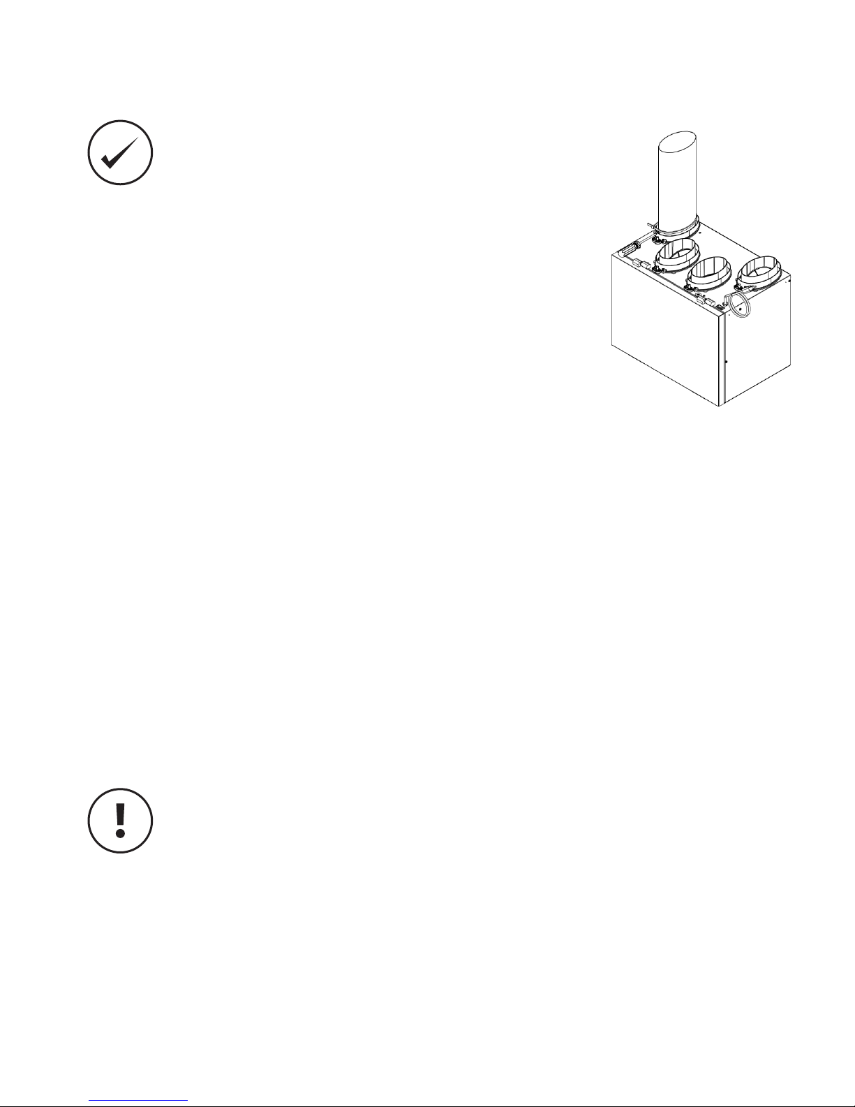
INSTALLING DUCT TO HRV
For flexible duct installation, slide flexible ducting onto duct connection. Then install a cable tie over flexible duct to prevent leakage
between the ducting and the duct connection.
In the case of solid ducting, slide duct over duct connection, screw in place and seal.
SUPPLY AIR GRILLES LOCATION
In homes without a forced air furnace, fresh air should be supplied to all habitable rooms, including bedrooms and living areas. It
should be supplied from high wall or ceiling locations. Grilles that diffuse the air comfortably are recommended. In homes with a
forced air furnace, you may want to connect the HRV to the furnace ductwork (see information below).
EXHAUST AIR GRILLES LOCATION
The stale air exhaust system is used to draw air from the points in the house where the worst air quality problems occur. It is
recommended that return air ducts be installed in the bathroom, kitchen, and laundry room. Additional return air ducts from
strategic locations may be installed. The furnace return duct may also be used to exhaust from. In this method, the exhaust air is
not ducted back from bathrooms, kitchens, etc to the HRV with “dedicated lines”.
AS PER BUILDING CODES AND INSTALLATION REQUIREMENTS FOR COMBUSTION APPLIANCES: AIR RETURN
DUCTS, OR OPENINGS FOR AIR RETURN, SHOULD NOT BE PLACED IN ENCLOSED SPACES CONTAINING
COMBUSTION APPLIANCES THAT ARE SUBJECT TO SPILLAGE

10
HRV INSTALLATION
LOCATION
The HRV must be located in a heated space where it will be possible to conveniently service the unit.
Typically the HRV would be located in the mechanical room or an area close to the outside wall where
the weatherhoods will be mounted. If a basement area is not convenient or does not exist, a utility
room may be used.
Attic installations are not normally recommended due to:
• The complexity of the installation
• Freezingconditionsintheattic
• Difficulty of access for service and cleaning
• No drain access
Connecting appliances to the HRV is not recommended. These include:
• Clothes dryer
• Range top
• Stovetop fan
• Central vacuum system
• Bathroom exhaust fans unless they are specifically designed for this purpose
These appliances may cause lint, dust or grease to collect in the HRV, damaging the unit.
Connecting any of
these types of
appliances to the
HRV will void your
warranty.
MOUNTING – WALL MOUNT
1. Attach bracket to wall
2. Lift unit & slide nuts into slots on bracket
3. Tighten screws to secure unit to bracket
4. Ensert the safety screws & place wall bumpers to level off the unit.
*Optional chain hanging kit available.
INSTALLING DRAIN LINE
Through normal operation and during its defrost mode, the HRV may produce
some condensation. This water should flow into a nearby drain, or be taken away by a condensate pump. The HRV and all condensate
linesmustbeinstalledinaspacewherethetemperatureismaintainedabovethefreezingpoint.A“P”trapshouldbemadeinthedrain
line. This will prevent odors from being drawn back up into the unit.
Safety screws
(included)
Place bumpers on
back of unit
(included)
16” (406mm)
2 Install the drain hose,
making a “P” trap
1 Install the drain nipple.
• Have a nearby power sup-
ply(120volts,60Hz)
• Choose a location which
allows the possibility of
mounting the unit to sup-
porting beams.
•The unit should be level
in order to allow proper
condensate drainage
• Tominimizenoise,donot
install unit in living area
•Ensure proper drainage
Table of contents
Languages:
Other Fantech Ventilation manuals


