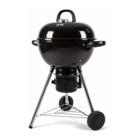
komodo KDSS4BRNBBQA User manual

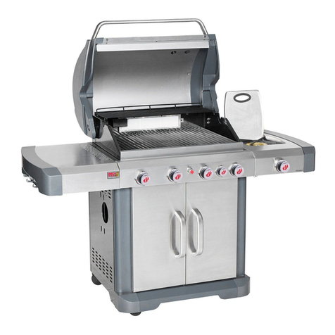
Product Desc: Outdoor BBQ Gas Grill 4B+SB
Model No.: KDSS4BRNBBQA
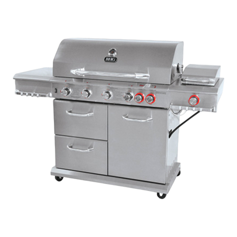
Model may not be exactly as shown

2
Congratulations On Your Purchase
Thank you and congratulations for choosing a quality barbecue as part of your outdoor entertaining world.
By following these instructions for safe and easy operation, you will enjoy years of satisfying, trouble-free outdoor
cooking.
Safety First
Australia has an excellent safety record when it comes to gas appliances. This reflects both the high quality of
appliances sold, as well as growing consumer awareness about safe practice. We urge you to follow the
guidelines below together with these instructions for safe use, to prevent overheating and to produce great
cooking results.
This barbecue is an outdoor appliance only. Under no circumstances should it be used indoors.
This barbecue has not been approved for marine use.
Do not perform any servicing on the barbecue yourself. This includes internal adjustment of the regulator and gas
valves. Servicing can only be carried out by authorized technicians.
It is important that you install your barbecue exactly as described in these instructions. In particular you should
keep the barbecue clear of combustible material, and you should check for leaks whenever a new connection is
made.
Do not store chemicals or flammable materials near this appliance.
Do not place articles on or against, or enclose this appliance.
The barbecue gets extremely hot while in use. Keep children away from the appliance until it has cooled to normal
temperatures.
It is a good idea to tie back long hair and loose clothing while cooking in case of unexpected flare ups.
Fat fires are the most common cause of problems in barbecues. They are caused by a build up of grease in the drip
tray and the inside of the barbecue frame. A fat fire can be difficult to put out, and will be dangerous if it spreads to
the gas hose. You should keep your barbecue clean to avoid this occurrence. Fat fires are not covered by the
warranty. Do not transport the barbecue whilst it is hot because there is a risk that the contents of the drip tray will
fall out. NEVER leave a barbecue unattended with any burners switched on. Always switch off all burners and
cylinders when the barbecue is not in use.
Take care when touching a hot barbecue, especially on surfaces close to the firebox or roasting hood.
Its fine to pre-heat with all burners on Hi and the hood closed, but NEVER let the temperature on the hood
thermometer exceed 250°Celsius.
When cooking with the hood closed, turn one or more burners to Low or OFF as required to keep the barbecue
from getting too hot. NEVER let the temperature on the hood thermometer exceed 250°Celsius.
NEVER leave all burners on Hi for more than 15 minutes, always stay in control by adjusting burners to Low and
OFF as required to maintain suitable cooking temperatures.
Follow all manufacturers’ instructions to periodically check for gas leaks.

3
Where To Put Your Barbecue
Most importantly, you must observe the clearances listed below and on the data sticker on your barbecue.
It will tell you how close you can put the barbecue to combustible surfaces (wood, gyprock, trees, wooden fences etc).
If you don’t follow these clearances, there is a chance that nearby surfaces will heat up and catch fire. If you purchased
your barbecue in a cart, you don’t need to be concerned with side clearances. The barbecue-cart combination has
been laboratory tested, and complies with relevant Australian Standards.
CLEARANCES FROM COMBUSTIBLE MATERIALS
Side and Back: 300mm. Vertically above: 900mm.
Keep the barbecue sheltered from the wind. Wind interferes with the flames and can prevent your barbecue from heating
up properly and can even damage some components.
Make sure the surface is level. This is safer, and makes cooking easier.
Don’t put the barbecue too close to windows or anywhere else where cooking smoke is likely to cause a problem.
Putting Your Barbecue In An Enclosure
This appliance must only be used in an above ground open-air situation with natural ventilation, without stagnant areas,
where gas leakage and products of combustion are rapidly dispersed by wind and natural convection.
Any enclosure in which the appliance is used must comply with one of the following:
(a) An enclosure with walls on all sides, but at least one permanent opening at ground level and no overhead cover.
(b) Within a partial enclosure that includes an overhead cover and no more than two walls.

4
(c) Within a partial enclosure that includes an overhead cover and more than two walls, the following shall apply—
(ⅰ) at least 25% of the total wall area is completely open; and
(ⅱ) at least 30% of the remaining wall area is open and unrestricted.
(d) In the case of balconies, at least 20% of the total of the side, back and front wall areas shall be and remain open
and unrestricted.

5
3. Explode view & hardware
PARTS LIST
NOTE: Some grill parts shown in the assembly steps may differ slightly in appearance
from Those on your particular grill model. However, the method of assembly remains
the same.
Key Description Qty Key Description Qty
1Side Burner Lid 132 Door Handle 2
2Rotate Rod, Side Burner Lid 233 Left Door 1
3Side Burner Grid 134 Door Bracket 1
4Side Burner 135 Back Panel 1
5Igniter Wire, Sideburner 136 Left Frame 1
6Located Pin, Side Burner 237 Fascia, Left Side Shelf 1
7Side Burner Base 138 Left Side Shelf 1
8Right Side Shelf 139 Thermal Baffle 1
9Fascia, Right Side Shelf 140 Grease Tray 1
10 Electronic Ignition Module 141 Firebox 1
11 Control Panel 142 Silicone Rubber Bumper 2
12 Gas Valve, Main Burner 443 Temperature Gauge 1
13 Side Burner Hose 144 Rotate Rod, Lid 2
14 Gas Valve, Side Burner 145 Lid 1
15 Manifold, Main Burner 146 Insulation Spacer,Lid 2
16 Control Knob Bezel 547 Bezel, Lid Handle 2
17 Control Knob 548 Lid handle 1
18 Regulator 1 49 Warming Rack 1
19 Cotter Pin 950 Cooking Griddle 1
20 Gas Bottle Holder 1 51 Cooking Grate 1
21 Bottom Shelf 152 Heat Diffusers 4
22 Door Magnet Box 153 Flame Carry Over Tube 3
23 Door Magnet 454 Main Burner 4
24 Caster 255 Electrode, Main Burner 1
25 Caster With Brake 256 Grease Accumulate Tray 1
26 Hose Fixed Pin 157 Mounting Plate of Thermal Baffle 2
27 Side Panel 258 Back Rail 1
28 Right Frame 159 Match Holder Chain 1
29 Match Holder Bracket 160 Silicone Rubber Bumper 2
30 Match Holder 161 Logo 1
31 Right Door 1
Not Pictured
Hardware Pack 1
Manual 1

6
PARTS DIAGRAM
Advice: Please remove all transit protection/packaging before assembly!

7
ASSEMBLY
CAREFULLY READ AND PERFORM ALL ASSEMBLY INSTRUCTIONS ON THE FOLLOWING PAGES.
Tools Required:
Adjustable wrench (not provided)
Screwdriver (not provided)
7/16” Combination wrench (not provided)
The following hardware is provided in blister pack:
Item Description Figure Quantity
1 M4X10 screw 39 pcs
2 M5X10 screw 6 pcs
3 M6X13 screw 16 pcs
4 M6 compression washer 8 pcs
5 M5 flat washer 4 pcs
6 AAA Battery 1pc

8
4. Assembly instructions
Bottom Shelf
Attach left side panel to left Frame (marked L) with (4) M4x10 screws to construct the Left Panel Assembly .
The Right Panel Assembly comes pre-constructed.
Attach sides of bottom shelf to left and right panel assemblies with (6) M4x10 screws. Do not fully tighten at
this time. The cart will not be level, however this will be corrected when the back panel is installed.
Attach door magnets to bottom shelf with (2) M4x10 screws.
M4x10 screw 12 pcs
side panel
Left Panel
Right Panel
Front
Bottom

9
Cart
Attach back panel to the left and right panel assemblies with (4) M4x10 screws. (A)
Attach back panel to bottom shelf with (1) M4x10 screw. (B)
Turn cart upside down. Align the bottom shelf side holes with leg holes.
Attach sides of bottom shelf to four legs with (4) M6x13 screws. (C)
Attach the two front leg ends to bottom shelf with (2) M5x10 screws. (C)
Screw the casters into each leg bottom end. Note: The casters with brakes should be mounted on the back
of bottom shelf. Tighten with caster wrench (provided with casters) counterclockwise. (D)
Fully tighten all screws, top and bottom.
M4X10 screws Qty: 5 pcs M5X10 screw Qty: 2 pcs M6X13 screws Qty: 4
AB
CD

10
Front Doors
Stand cart upright.
Align door bracket holes with holes on front legs. Attach door bracket to left and right panel assemblies
with (4) M4x10 screws. Note: Attach bracket so that magnets are at bottom.
Remove the screws and washers pre-assembled to the door handle ends, and use them to attach handles
to doors.
Insert the lower door pin into the hole on the bottom shelf. Push down the upper door pin, align it beneath
hole in door bracket, and release pin so that it inserts in hole.
Repeat this for the other door.
Note: If the doors do not line up when closed or cannot close freely, loosen the screws on the door pin
bracket. Adjust the door pin bracket as necessary, and retighten screws. Recheck door alignment once grill
is completely assembled and readjust if necessary.
M4x10 screw 4 pcs

11
4Thermal baffle
Fix the mounting plate of thermal baffle on the left and right flame with (4) M4x10 screws.
Fix the thermal baffle on the mounting plate wiith (4) M4x10 screws.

12
Grill Head to Cart
This step requires two people to lift and position grill head onto cart.
Remove the tie wraps securing regulator hose to underside of grill head. Pull hose and igniter wires out to
side of grill head.
Carefully lower the grill head onto the cart. Make sure the regulator hose and igniter wires are hanging
outside the cart. Open lid and attach head to cart with (4) M6x13 screws and M6 compression washers.
M6x13 screw 4 M6 compression washers 4 pcs

13
Left Side Shelf
Attach fascia to left side shelf with (2) M5x10 screws and M5 flat washers. (A)
Hang shelf onto brackets on left side of firebox.
Attach shelf to firebox as follows:
- From inside to outside of firebox with (2) M6x13 screws and M6 compression washers. (B)
- From outside to inside of firebox with (2) M6x13 screws. (C)
Attach fascia to control panel with (1) M4x10 screw. (C)
M6x13 screw 4 pcs M6 compression washers 2
M5x10 screw 2 pcs M5 flat washers 2 pcs
M4x10 screw 1 pcs
A
BC

14
Right Side Shelf
Remove sideburner grate from sideburner before assembling and attaching the right side shelf.
Attach fascia to right side shelf with (2) M5x10 screws, and M5 flat washers.
Hang right side shelf onto the brackets on right side of firebox.
Attach shelf to firebox as follows:
- From inside to outside of firebox with (2) M6x13 screws and M6 compression washers.(A)
- From outside to inside of firebox with (2) M6x13 screws. (B)
Attach fascia to control panel with (1) M4x10 screw. (C)
M6x13 screw 4 pcs M6 compression washers 2
M5x10 screw 2 pcs M5 flat washers 2 pcs
M4x10 screw 1 pcs
AB

15
8FIT THE SIDE BURNER AND HOSE ASSEMBLY (It’s best to do this with another person to help)
(a) Unscrew and remove two front screws and washers holding side burner in place. Note: Do not loosen
electrode screw.
(b) Loosen side burner in side shelf.
(c) Remove knob and bezel from side burner control valve. To remove, pull knob straight out from valve stem.
Unscrew bezel from valve face and set the two screws aside.
(d) Insert valve stem through hole in fascia.
(e) Place side burner tube over the valve, making sure that valve is inside side burner tube.
(f) Attach bezel to fascia and valve face with previously removed 2 screws.
(a) (b)
(d)
(c)
(e) (f)

16
(g) Push control knob onto side burner valve stem.
(h) Reattach side burner to side burner shelf with the 2 previously removed screws and washers. Fit the side
burner TRIVET (N).
( i ) Insert the small tip of the main burner wire and side burner wire into the two module sockets.
( j ) Unscrew igniter cap from control panel. Insert one AAA battery (provided in bolt pack) into battery slot with
positive end (+) facing outward. Screw igniter cap back onto panel.
(g)
(j)
(i)
(h)

17
FAT CUP
Place the FAT CUP (W) into the place as figure show.

18
Regulator hose
Feed the regulator hose through the hose bracket on Right Front Leg and fix with cotter pin.

19
11 Heat Diffusers, Cooking Grate, Cooking Griddle and Warming Rack
Place heat diffusers over burners by inserting tabs into slots in front and back of firebox.
Place heat diffusers over burners. Diffusers will fit in firebox in either direction. Fit tabs in firebox front
Through slots in diffuser tips. Fit diffuser tips over tabs in firebox rear at front and rear of firebox.
Insert warming rack into brackets at top of firebox as shown.

20
5. Installing with gas supply system
Checking The Gas Type
Before assembling your barbecue, you should ensure the barbecue is suited to the type of gas which you are going to
use.
LPG (also Known As Propane):
Barbecues suited to LPG should have an orange sticker on the side saying “PROPANE ONLY”.
This is most commonly supplied as a portable 4 kg or 9 kg gas cylinder, which can be refilled or swapped at petrol
stations or other retailers when empty.
Some homes have twin 45 kg LPG cylinders permanently installed near an outside wall. These cylinders supply LPG
gas to many appliances in the home via copper pipes, and are filled as required by the gas supply company.
Natural Gas
This barbecue is not suitable for Natural Gas.
It is extremely dangerous to use the barbecue with the wrong type of gas. Fire or explosion may result.
Portable LPG Cylinders (Supplied Separately)
Fill and leak check the cylinder before placing it in or attaching to the barbecue.
Place the LPG cylinder into the well in the base of the cart, with the cylinder opening facing forwards.
Take the hose that came with the barbecue, check that it has a rubber seal on the regulator end of it, and connect this
end of the hose to the gas cylinder. You won’t need a spanner here. Just turn the fitting in an anticlockwise direction
and hand tighten as much as you can. This should seal it sufficiently.
Conduct a leak test as outlined on Page 22 before use.
Table of contents
Other komodo Grill manuals