Konecranes SMV 10-600B User manual

Instruction manual SMV 10 600B – 60 1500B Publ. no. 6196.082 1117, Version 02 1
Model range
SMV 10-600B – SMV 60-1500B
Instruction manual SMV 10 600B – 60 1500B Publ. no. 6196.082 1117, Version 02
CONDESIGN INFOCOM AB, SWEDEN

2Instruction manual SMV 10 600B – 60 1500B Publ. no. 6196.082 1117, Version 02
Your machine from Konecranes
YOUR MACHINE FROM KONECRANES
LIFTTRUCKS
This user manual tells you all you need to know about
starting, driving, servicing and maintaining your machine
from Konecranes Lifttrucks.
Correct maintenance and operation will preserve the
machine over a long and profitable operational life time and
will utilise its features.
The phrases "front", "rear", "right" and "left" refer to the
position in which the component in question is installed as
viewed from the driver's seat.
Adhere to all the suggestions in the manual for the operation
of the machine and perform the maintenance and
inspections that are prescribed in the maintenance schedule,
regularly and on time using the specified lubricants.
Operation and maintenance must only be performed by
qualified staff. The working environment instructions must
always be adhered to.
In particular, we wish to point out the importance of
adhering to both general traffic regulations and the
guidelines that are necessary for a safe use of the machine
and for the prevention of work-related accidents.
The regulations that are applicable to the use of industrial
machines must be strictly adhered to by the work managers,
drivers and maintenance staff.
The responsibility for any risks that may occur when using the
machine for applications for which it has not been approved
rests with the user and not Konecranes Lifttrucks. The
intended use of the machine is clear from its EC assurance.
Konecranes Lifttrucks are constructed for transport and
lifting of such loads as stated on the lifting capacity plate. No
alterations, and in particular no additions or modifications,
may be performed on the machine without the approval of
the manufacturer.
For any optional equipment, please refer to the the user
instructions issued by the manufacturer.
TECHNICAL REMARK
For questions on machines from Konecranes Lifttrucks and
when ordering spare parts, contact your nearest authorised
dealer. Please make sure you state the correct delivery address.
For any repairs, please only use Konecranes Lifttruck original
spares. This is a prerequisite for ensuring that your machine
from Konecranes Lifttrucks shall maintain its original
technical standard.
When ordering spare parts, it is important that you state the
part number given in the spare parts list and also the
following information:
• Machine designation:
• The serial number/year of manufacture of the machine:
• Delivery date:
When ordering parts for the following units, their individual
manufacturing number should be stated:
• Engine no.:
• Mast/boom no.:
• Mast/boom lifting height:
• Hydraulic pump no.:
• Transmission no.:
•Driveaxleno.:
(The individual numbers are stated on the machine card.)
When the machine is delivered, the details on the machine
type plate should be written down in this user manual.
DELIVERY INSPECTION
Every machine from Konecranes Lifttrucks is checked very
carefully before leaving the factory in order to ensure that it
is in good condition and fully equipped as per the order.
Authorised Konecranes Lifttrucks dealers are then obliged to
inspect the machine once more prior to delivery to the
customer.
In order to avoid later complaints and problems, the
customer should also inspect the machine to ensure that it is
in fully operational condition and fully equipped at the
point of delivery and sign for the receipt of the machine
from the dealer.
Always perform maintenance, lubrication, checks and daily
inspections in accordance with the instructions in this book.
Prior to taking the machine into use, the inspection points in
accordance with the warranty/delivery report must be
inspected.
The warranty/delivery report must be filled in and returned
to Konecranes Lifttrucks within a week after the first time of
use in order for the warranty to be valid from the first time of
use. If the warranty/delivery report is not returned within
aweek, the warranty is valid from the day the machine was
delivered from Konecranes Lifttrucks.
The following technical manuals are enclosed with every
machine:
• 1 Spare parts catalogue
• 1 Instruction book
• 1 Driver user manual
•1Machinecard
When contacting your authorised dealer, please always state:
• Machine designation
• Machine serial number
•YearofManufacture
Instruction manual SMV 10 600B – 60 1500B Publ. no. 6196.082 1117, Version 02

Instruction manual SMV 10 600B – 60 1500B Publ. no. 6196.082 1117, Version 02 3
Table of contents
TABLE OF CONTENTS
YOUR MACHINE FROM KONECRANES
LIFTTRUCKS ................................................................. 2
Technical remark .............................................................. 2
Delivery inspection ........................................................... 2
TABLE OF CONTENTS ................................................ 3
SAFETY REGULATIONS .............................................. 4
Safety rules ....................................................................... 4
Warning texts and important information ........................ 5
Before driving ................................................................... 6
Preventions of accidents .................................................... 6
Norms .............................................................................. 6
PRESENTATION OF THE MACHINE ........................ 7
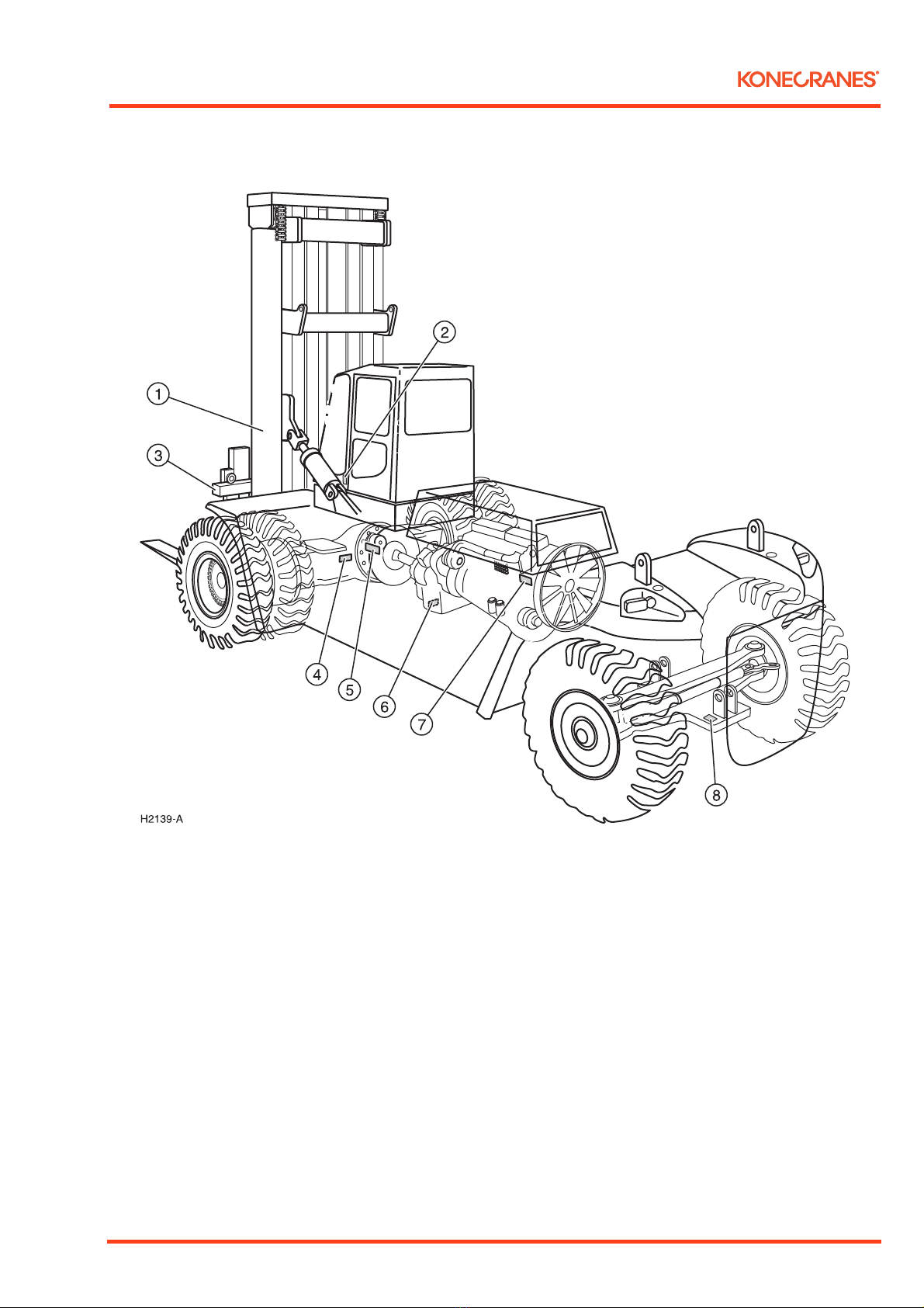
Technical description ........................................................ 7
Overview of the machine .................................................. 8
ID-plates and serial number .............................................. 9
Cabin controls and indicators ......................................... 10
Warning indicators and gauges ....................................... 11
Description of Drive monitor IQAN MD3 .................... 12
Driver seat ...................................................................... 17
Steering .......................................................................... 18
Declutch function ........................................................... 18
Parking brake switch ....................................................... 18
Emergency stop .............................................................. 19
Ventilation ..................................................................... 20
Cabin tilting ................................................................... 21
Locking of doors ............................................................. 21
Electrical system ............................................................. 22
DRIVING AND MANOEUVRING OF LOAD .......... 26
Start the engine ............................................................... 26
Stop the engine ............................................................... 27
Driving ........................................................................... 28
Manoeuvring of load ...................................................... 31
Manoeuvring of mast ...................................................... 32
LIFTING AND TRANSPORTING THE MACHINE .... 37
Towing ........................................................................... 37
Lifting the machine ....................................................... 38
Transport ....................................................................... 40
SERVICE AND MAINTENANCE ............................... 41
General ........................................................................... 41
Daily inspection and service prior to start ....................... 43
Cleaning ......................................................................... 49
Pressure draining of the hydraulic system ........................ 50
Wheel replacement ......................................................... 50
Retightening of bolt joints, torque .................................. 57
Overview lubrication schedule ........................................ 62
Engine, oil, oil filter and oil cleaner, Scania .................... 64
Fuel system, Scania ......................................................... 66
Engine, oil, and oil filter, Volvo ...................................... 68
Fuel system, Volvo .......................................................... 70
Air intake system ............................................................ 72
Transmission DANA, oil, oil filter and breathing valve ... 74
Transmission ZF, oil, oil filter and breathing valve ......... 76
Driving shaft, inspection and replacement of oil ............ 78
Hydraulic system ........................................................... 80
Lubrication .................................................................... 82
Inspection of the cooling system .................................... 85
Drive belt ....................................................................... 86
Engine ........................................................................... 86
Inspection of the battery ................................................ 87
Control steering axle bearing .......................................... 88
Wheel bearings .............................................................. 88
Spindle bearing .............................................................. 89
Inspection of the exhaust system for leaks ...................... 90
Fuel tank ........................................................................ 90
Wiper blade replacement ............................................... 91
Weld construction ......................................................... 91
Mast and fork carriage ................................................... 92
Parking brake ................................................................. 94
INSPECTION AND MAINTENANCE SCHEDULE .... 96
Delivery inspection and start-up .................................... 96
Service items .................................................................. 96
Daily inspection and service prior to start ...................... 97
Service items for the first 150 hours ............................... 97
Inspection and maintenance schedule ............................ 98
Service schedule engines ................................................. 99
Liquid volumes ............................................................ 100
FUEL AND OIL RECOMMENDATIONS ............... 101
The quality of the engine oil ........................................ 101
Extended oil replacement intervals ............................... 101
Recommended fuels and hydraulic oils ........................ 102
Instruction manual SMV 10 600B – 60 1500B Publ. no. 6196.082 1117, Version 02

4Instruction manual SMV 10 600B – 60 1500B Publ. no. 6196.082 1117, Version 02
Safety regulations
SAFETY REGULATIONS
SAFETY RULES
• Adhere to the local safety regulations
• The machine may only be operated by drivers who have
been specially trained and who have the permission of
the work management.
• Remember: The Road Traffic Act and the Highway Code
always applies!
• Prior to start: Ensure that there are no persons or other
objects in the way of the machine or its equipment.
• Do not block doors and/or emergency exits.
• The machine must not be used if there is a fault with the
brakes, steering, lifting device or other important
components.
• It is not allowed to bring along passengers.
• Lifting persons with the machine is prohibited.
• Never exceed the lifting capacity of the machine – see the
type plate and load chart.
• The load must always be transported in a lowered position.
• Always repair damage and wear that impacts safety/
functioning and the useful life.
• The hydraulic system of the machine is equipped with
a hydraulic accumulator using a high pressure. Take great
care when working with the hydraulic system. Only
maintenance staff with experience of the hydraulic
system may interfere with it.
• Use safety equipment – breathing mask, protective
goggles, hearing protection, gloves, helmet – as necessary.
• High pressure tyres. Always follow the instructions for
emptying and filling of the tyres.
Instruction manual SMV 10 600B – 60 1500B Publ. no. 6196.082 1117, Version 02

Instruction manual SMV 10 600B – 60 1500B Publ. no. 6196.082 1117, Version 02 5
Safety regulations
WARNING TEXTS AND IMPORTANT INFORMATION
There are three different types of warning texts in the
instruction manual. They are divided into different levels of
danger. All warning texts are preceded by a warning symbol.
This warning symbol makes the reader
aware of areas that may be associated with
risk of personal injury and refers them to
notices in the instruction manual.
DANGER
Situation that may lead to severe personal
injury or fatality if regulations are not
followed.
WARNING
Situation that may lead to personal injury
if regulations are not followed.
TAKE CARE
Situation that may lead to damage to the
product if regulations are not followed.
Always read the instructions that follow the warning symbol
or informative text.
Important information is indicated by the abbreviation
NOTE. The information is not necessarily do to with safety
but may also be about making the work easier or clarifying
information.
NOTE
Used to indicate important information that makes work or
handling easier.
Read the instruction manual carefully
before you start using the machine.
Incorrect usage may lead to severe
injury to person, product or property.
The instruction manual contains
important information on operation
and safety and must always be located
by the machine. Never use a machine that does not have an
instruction manual.

6Instruction manual SMV 10 600B – 60 1500B Publ. no. 6196.082 1117, Version 02
Safety regulations
BEFORE DRIVING
Responsible staff, in particular drivers and service personnel,
must be instructed in the regulations for normal and safe use
of industrial machines that accompany this user manual.
Adhere to the guidelines and safety rules that are available for:
• using industrial machines,
• roads and work places,
• drivers (rights, duties and rules of conduct),
• any optional equipment,
• different types of drive units,
• service (maintenance and inspection),
• check for the prevention of accidents.
The driver (/owner) or other persons of responsibility must
ensure that the guidelines above and all safety rules are
adhered to.
When a trained driver is to commence driving the machine,
instruct him on:
• the special functions of Konecranes Lifttrucks,
• extra equipment,
• specific operational features.
Driving, manoeuvring and steering should be practiced until
the driver is completely comfortable with this. Only then
should training in stacking manoeuvring commence. The
stability of the machine within the work area can only be
guaranteed if the machine is used correctly. If tendencies of
tipping over occur due to prohibited manoeuvres or incorrect
driving, the instructions given must be adhered to completely.
Take the following factors of environmental impact into
consideration:
1. Driving
Exhaust emissions, fuel consumption, noise level, leaks
(oil, fuel, liquids) increase if the machine is driven and
operated incorrectly.
2. Service
Oils, fuels, filters and filter elements, cleaning agents
must be handled in a way suitable for the environment.
3. Repairs
Metal, batteries, electronics, rubber (tyres, hoses, seals),
emulsions and chemicals must be handled or recycled in
a way suitable for the environment in accordance with
local regulations.
PREVENTIONS OF ACCIDENTS
In some countries, machines must be inspected at least once
annually by trained personnel in accordance with regulations
for the prevention of accidents.
Authorised dealers of Konecranes Lifttrucks may provide
further information on this.
NORMS
This machine is constructed and built in accordance with the
following norms:
Machine directive 2006/42/EC
Safety for industrial trucks EN 1551
Stability for industrial trucks ISO1074
Noise levels 2005/88/EC
Vibrations EN 13059
Emission 2004/26/EC
EMC 2004/108/EC

Instruction manual SMV 10 600B – 60 1500B Publ. no. 6196.082 1117, Version 02 7
Presentation of the machine
PRESENTATION OF THE MACHINE
TECHNICAL DESCRIPTION
The designation SMV 33-1200 B means:
SMV = Product name
33 = 33 ton lifting capacity,
1,200 = 1,200 mm load centre
B = series designation
The engine is a water cooled, turbo charged 6 cylinder diesel
engine. The engine drives a transmission through a torque
converter. DANA has a transmission version with four
forward gears and four backward gears. ZF has a transmission
version with four forward gears and three backward gears.
Both DANA and ZF have a transmission version with three
forward gears and three backward gears.
All machines are provided with a gear lever for four forward
but only three gears can be activate on certain models. The
gear change is done electrically with gears for driving
forward/backward. The torque converter is equipped with
an oil cooler under the engine cooler. The transmission has
a disconnect valve that is manoeuvred via the brake pedal
in the cabin.
The disconnection valve disconnects the transmission so that
the operator can control the braking and at the same time
retain a high engine revolution during stacking.
The front axle is driven by the transmission via the prop
shaft. This axle is of a double-reduction heavy duty type with
a conic pinion as its primary gear, hub planetary gear as its
secondary gear, load reduced axle pegs and conical roller
bearings.
The steering shaft is mounted in "spherical" bushings that
allow sufficient wheel movements for stability on uneven
surfaces. The parallel tie rods are between the steering
cylinders and the wheel axles.
The brake system consists of a oil cooled wet disc brake
system. The foot brakes are operated using the foot brake
valve and affects the drive axle.
The parking brake operates electrically and affects a hydraulic
cylinder on the prop shaft. The parking brake is always active
as long as it has not been released using electrical energy.
The axial piston pumps together with a gear pump are fitted
directly on the transmission. The gear pump builds up the
accumulator pressure for the foot and parking brakes. The
variable piston pump provides the steering system and the
different lift functions with pressure. The system is load
sensing.
The steering is completely servo assisted. In the event of an
engine breakdown, it is still possible to steer the machine for
a limited period of time without power assistance but it will
be heavy.
WARNING
In the event of engine breakdown, the
machine must be stopped in a safe manner.
Machine sizes 10-16 are equipped with a directional control
valve and machine sizes 18-60 are equipped with two. These
directional control valves are fitted to the chassis and
operated from the cabin using power assisted levers to the
right of the driver. These control the functions for mast lifts,
tilts, sideshift movement of the fork carriage and the fork
spreading and any extra functions.
The mast consists of an outer and an inner mast, a fork
carriage, two lift cylinders and two tilt cylinders. The inner
stand section moves along the outer using mast wheels and
support rollers. The mast is mounted on two axles in the
chassis using bearings. The fork carriage is of a rolling type
with sideshift movement and fork spreading.
The driver's cabin fulfils international safety standards and is
suspended on the chassis on rubber mounts to protect the
driver from vibrations. Getting into the cabin is done from the
left using the steps in the machine. When the driver seat is
turned 90°, it is also possible to leave the cabin to the right.
All hydraulic controls for the lifting functions are situated on
the console to the right of the driver seat.
The parking brake, switches for electric optional equipment's,
instruments, gauges and warning indicators are on the front
instrument panel.
Gear change controls, levers for driving direction indicators
and the windscreen wipers are on the steering column.
The electrical system is 24 volt using two heavy duty batteries
connected in line.
Instruction manual SMV 10 600B – 60 1500B Publ. no. 6196.082 1117, Version 02

8Instruction manual SMV 10 600B – 60 1500B Publ. no. 6196.082 1117, Version 02
Presentation of the machine
OVERVIEW OF THE MACHINE
1. Mast
2. Fork carriage
3. Forks
4. Tilt cylinder
5. Lift cylinder
6. Drive axle
7. Engine hood
8. Steering axle
9. Counter weight
10. Driver's cabin

Instruction manual SMV 10 600B – 60 1500B Publ. no. 6196.082 1117, Version 02 9
Presentation of the machine
ID-PLATES AND SERIAL NUMBER
1. Mast number
2. Load capacity plate
3. Fork carriage number
4. Driving axle number
5. Chassis number
6. Transmission number
7. Engine number
8. Steering axle number

10 Instruction manual SMV 10 600B – 60 1500B Publ. no. 6196.082 1117, Version 02
Presentation of the machine
CABIN CONTROLS AND INDICATORS
1. Steering wheel
2. Wiper windscreen
3. Main beam/dipped beam
4. Horn
5. Driving direction indicator
6. Windscreen washer
7. Adjustment lever steering wheel
8. Control levers hydraulics
9. Accelerator pedal
10. Brake pedal
11. Declutch
12. Cooling (AC)
13. Recirculation
14. Heater controls
15. Fan
16. Instrument panel and switches
17. Ignition lock
18. Emergency stop
19. Drive monitor IQAN MD3
20. Gear lever
The placing of the controls may vary from machine to machine depending on the requirements of the customer. The image above
shows the standard placing of controls.

Instruction manual SMV 10 600B – 60 1500B Publ. no. 6196.082 1117, Version 02 11
Presentation of the machine
WARNING INDICATORS AND GAUGES
1. Work light mast
2. Work light roof
3. Work light extra
4. Driving light
5. Parking brake
6. Washing roof/rear screen
7. Wiper rear screen
8. Wiper roofscreen
9. Hazards
10. Rotating warning lights
11. Lever steering (optional)
12. Central lubrication (optional)
13. Central lubrication (optional)
14. Activation diagnostics engine (optional)
15. Ignition lock
16. Emergency stop engine
17. Indicator main beam
18. Indicator driving direction Right/Left
19. Drive monitor IQAN MD3
20. Warning indicator
The placing of the controls may vary from machine to machine depending on the requirements of the customer. The image above
shows the standard placing of controls.

12 Instruction manual SMV 10 600B – 60 1500B Publ. no. 6196.082 1117, Version 02
Presentation of the machine
DESCRIPTION OF DRIVE MONITOR IQAN MD3
The function of the trip computer is to, by using information from
different sensors, analogue and digital signals, optimally control the
hydraulic system and drive line. The driver has a total overview of
the activities of the machine during operation.
1. Lever steering active (optional)
2. Low coolant level (optional)
3. Warning low fuel level
4. Low battery power
5. Low oil pressure engine
6. Parking brake activated
7. Low accumulator pressure, brakes
8. Indication twist look
9. Load weight (optional)
10. Confirms choice
11. Engine temperature
12. Fuel level
13. Adjustment and measure page
14. Previous page
15. Information page
16. Hydraulics page
17. Tranmission page
18. Engine page
19. Eco driving
20. Engine RPM
21. Clock
22. Gear position

Instruction manual SMV 10 600B – 60 1500B Publ. no. 6196.082 1117, Version 02 13
Presentation of the machine
Engine page
•PressF1onthestartpage.
The engine page shows:
• The real rpm of the engine
• The temperature of the engine
• Battery power
• Engine oil pressure
• Engine rpm requested by the Transmission
• Requested rpm in % of maximum value
• Operational time engine
• Diagnostics engine, warning and indicator lights (Scania
engines)
• F1 – Return to start page
• F2 – Eco driving page
• F3 – Stops the engine
• F4 – Shows error codes (Scania engines)
Eco driving page
• Press F2 on the engine page
The Eco driving page shows:
• Current fuel consumption in % of maximum fuel consumption
•Enginetype
• Current fuel consumption (litres/hour)
• Average fuel consumption (litres/hour)
• Operational time since last reset
• Estimated fuel consumption, F4 (litres)
• Total amount of consumed fuel in litres since the engine was
started
• F1 – Return to start page
• F3 – Reset, expect for the value Total Fuel Used
• F4 – Estimated fuel consumption (litres)
Gear #
F/R
Transmission page Dana
•PressF2onthestartpage
Transmission page Dana shows:
• Driving speed
• Accelerator position 0-100%
• Input rpm Transmission
• Temperature Transmission
•Drivingtime
• Brake temperature drive axle
• Gear position 0-4
• Driving direction indicator F-R
• Error codes from transmission
• OK – Activates the diagnostics page
• F1 – Return to start page
• F2 – Start in first gear
• F3 – Manual gear change
• F4 – Error codes from transmission Scrolls error codes

14 Instruction manual SMV 10 600B – 60 1500B Publ. no. 6196.082 1117, Version 02
Presentation of the machine
Transmission page ZF (optional, replaces DANA)
• Press F2 on the start page
Transmission page ZF shows:
• Driving speed
• Accelerator position 0-100%
• Input rpm Transmission
• Temperature converter
• Temperature oil tray
• Brake temperature drive axle
• Gear position 0-4
• Driving direction indicator F-R
• Status transmission
•Drivingtime
• F1 – Return to start page
• F2 – Start in first gear
• F3 – Manual gear change
• F4 – Activates the diagnostics page
Hydraulics page (optional)
• Press F3 on the start page
The hydraulics page shows:
• Pressure lift cylinder
•Tiltangel
• Height indicator
•Weight
• Last added weight
• Total added weight
• Weight calibration without load
• Weight calibration with known load
• F1 – Return to start page
• F3 – Add "weight" to "total added weight"
• F4 – Resets all measurements
Information page
• Press F4 on the start page
The information page shows:
• Machine model
• Serial number
• Delivery date
• Container counter (the first value cannot be reset)
• Container counter (the second value can be reset using F4)
• Operational time counter (the first value cannot be reset)
• Operational time counter (the second value can be reset using F3)
• F1 – Return to start page
• F3 – Resets the operational time counter
• F4 – Resets the container counter

Instruction manual SMV 10 600B – 60 1500B Publ. no. 6196.082 1117, Version 02 15
Presentation of the machine
Adjustment and measuring page
•Presson the start page
The adjustment and measure page shows:
• Any alarm, warning of message is shown
• F1 – Shows submenu Adjust
• F2 – Shows submenu Measure
• F3 – Shows submenu Settings
• F4 – Shows submenu Info
•– Cancel
•– Return to previous page
Settings page
• Press F3 on the adjustment and measuring page
The settings page shows:
• F1 – Shows display settings
• F2 – Shows the page for setting date and time
• F3 – Shows language settings page
•– Return to previous page
•– Return to the adjustment and settings page
Display settings page
• Press F1 on the settings page
The display settings page shows:
• F1 – Return to start page
• F2 – Setting of background light
• F3 – Setting of screen saver
• Scroll using the arrow keys and save with OK
•– Return to previous page
•– Return to the adjustment and settings page

16 Instruction manual SMV 10 600B – 60 1500B Publ. no. 6196.082 1117, Version 02
Presentation of the machine
Language adjustment page
• Press F3 on the settings page
The language settings page shows:
• Select a language using the arrow keys
• Save by pressing OK
• F1 – Return to start page
•– Return to previous page
•– Return to the adjustment and settings page
Presentation of error messages
This message is shown when the electronic register input data from
sensors etc. are outside the permitted ranges.
"Low error" or "High error"
The message indicates sensor fault, cable fault or input fault on
module.
The example in accordance with the error message shows:
• Type of message
•Nameofsensor
• Type of fault
• For fault finding, it is clear to which control unit and which pin
the sensor is connected.
• F2 – Confirm the error message The error message disappears
from the screen but the error remains with the machine.
• F3 – Scrolls through more error messages.
•– Return to the adjustment and settings page

Instruction manual SMV 10 600B – 60 1500B Publ. no. 6196.082 1117, Version 02 17
Presentation of the machine
DRIVER SEAT
• In order to set the height of the chair, turn the knob (3)
clockwise for raising and counter-clockwise for lowering.
• To adjust the tilt of the seat cushion, adjust with knob (2).
• Set the back rest to the correct position with knob (1).
•
H2187-A
5
4
1
Lift the handgrip (4) to adjust the forward/backward position of
the chair.
• Adjust the lumbar support with knob (5).
•Height limiter with blocking (6).
– Position 1 lever to the right is full suspension.
– Position 2 one step to the left is limited suspension.
– Position 3 two steps to the right is blocking (delivery position).
• Adjust the arm rest angle with knob (7).
WARNING
Never drive the machine without putting on the
seat belt properly.
Danger of serious personal injury or fatality.
The seat belt must always be used when driving the machine.
WARNING
Never drive the machine if the seat is not locked
in its position.
Danger of serious personal injury or fatality.
Uncontrolled movements of the driver due to the fact that the
seat is not locked in its position may lead to an incorrect
manoeuvring of the machine.

18 Instruction manual SMV 10 600B – 60 1500B Publ. no. 6196.082 1117, Version 02
Presentation of the machine
STEERING
Very little effort is required to turn the steering wheel thanks to the
power assisted steering system.
In order to reduce unnecessary tyre wear, the steering wheel should
only be turned when the machine is moving.
DECLUTCH FUNCTION
•Release the accelerator pedal (1).
• Activate the declutch using the foot switch (2).
• If the switch is pressed further together with the pedal, the
brakes are applied further.
• When braking only with the brake pedal (3), the disconnection
is only activated once the brakes have been applied.
PARKING BRAKE SWITCH
•The parking brake switch (2) is located on the instrument panel.
• Avoid using the parking brake for braking the machine unless it
is an emergency.
• When the parking brake is activated, the warning indicator (1)
is lit.
• If the driver leaves the driver seat without having activated the
parking brake, a signal is sound.

Instruction manual SMV 10 600B – 60 1500B Publ. no. 6196.082 1117, Version 02 19
Presentation of the machine
EMERGENCY STOP
• When using the emergency brake (press button (1) downwards),
all functions are switched off. The parking brake is activated and
the engine stops.
WARNING
There is a risk of tipping when using the brake
whilst the machine is moving. Danger of serious
personal injury and damage to the vehicle.

20 Instruction manual SMV 10 600B – 60 1500B Publ. no. 6196.082 1117, Version 02
Presentation of the machine
VENTILATION
A = Heat
• (1) Temperature
•(2)Fan
B = AC:
• (1) Temperature
• (2) Fan
• (3) Recirculation
• (4) Cold
C = ACC:
• (1) Temperature
• (2) Fan (stepless)
•(3)Recirculation
•(4)Cold
Settings for different types of weather
• Warm weather with normal air humidity
– Open the fresh air intake
– Close the heat regulator
– Switch on the cooling and set the cold temperature to the
desired position.
• Very warm weather with high air humidity
– Close the fresh air intake
– Close the heat regulator
– Switch on the cooling and set the cold temperature to the
desired position.
• During autumn and early winter with high air humidity with
rain, slush and mist on the windows
– Switch on the cooling
– Open the fresh air intake
– Crank open a window so that the air can circulate in the cabin.
– Increase the heat if necessary.
• Cold weather in the winter
– Open the fresh air intake, switch off the cooling
– Set the heat to the desired position.
• Very cold weather with low air humidity
– Close the fresh air intake
– Switch off the cooling.
– Set the heat to the desired position.
• Winter during cold and dry periods with low degree of use
– Switch on the cooling and allow the compressor to work for
a few minutes once a week so that connections, seals etc. are
lubricated.
This manual suits for next models
18
Table of contents