ep ESL122 User manual

ESL122
Original Instruction Part No.508000004526
V1 12/2020
Operation Manual

Thank you for buying our products.
The manual will show you the way of correctly using the truck as well as relevant preventive
maintenance and safety operation. The truck should be operated only by well-trained professionals
and by no means by non-working personnel. Operators are supposed to read through the manual
before actually operating the truck.
With the continuous upgradation and improvement of our company’s products, you may nd a
slight dierence existing between your carrier and some introductions in the manual.
All the information, specications and illustrations in the manual are eective in times of printing
and our company maintains the right to modify the specication (s) or design (s) of our products at
any time without any beforehand notication.
Indicates an extremely hazardous situation. Failure to comply with this instruction will
result in severe irreparable injury and even death.
Please strictly adhere to these safety instructions to avoid personal injury or major
damage to equipment.
Please pay attention to the important safety instructions.
Pay attention to Instruction.
i
CAUTION
NOTE
WARNING
DANGER
Preface
Explanations on the manual
Safety signs and corresponding esplations

Intended use
The lift truck is designed for transporting and stacking the loads stated in the load capacity
diagram.
In particular we refer to:
• the safety rules of your trade association.
• the special measures required for driving onpublic roads in accordance with the StVZO
(Road Trac Licencing Regulations).
• other local regulations.
The rules for the intended and approved use of industrial trucks must be followed
under all circumstances by the responsible persons, especially by the operator and
service personnel.
The user, and not Manufacturer, is responsible for any danger arising from applications not
authorised by the manufacturer.
If you want to use the truck for applications not mentioned in this manual, please rst contact your
authorised dealer.
No changes, particularly no modications and additions, may be made to the truck without the
approval of the manufacturer.
In the manual, “equipment user” refers to any natural person or legal person directly using or
appointing or authorizing others to use the carrier. In such special situations as renting or sales,
the “equipment user” represents the interested parties supposed to bear operation obligations
as specied by the contractual terms concluded between equipment owner and corresponding
users. Equipment users must ensure the use of the carrier only for purposes specied and timely
eliminate all the dangers that may threaten the life and health of the users themselves or any other
third party, in addition to which they must also strictly abide by accident prevention provisions,
other safety technology provisions and equipment operation, maintenance and repair guidelines,
and ensure that all the operators seriously read and completely understand the contents of the
operation instruction.
Should any violation of the operation instruction occur, the quality guarantee of our company will be
invalid automatically, and our company will assume none of the responsibilities for losses resulting
from any nonstandard operation of the equipment implemented by any client, equipment user or
any third party without the authorization of the client service department of our company.
Obligations and responsibilities of equipment user
This product has a compact chassis, 4-point ground contact, balanced tiller and a microprocessor
electronic control system.The machine is lightweight, highly ecient and easy to handle.
Design
The latest ergonomic and practical design, adaptable to all operators and working conditions.
Control handle
The composite construction control handle head provides excellent impact resistance.
The ergonomic control layout is suitable for left-handed and right-handed operators.
The horn, lifting and lowering devices can be operated using one hand without changing grip.
The emergency reverse switch integrated into the tiller head protects the operator if the truck
recoils.
Series

Equipment ret
Driving
The electronic control unit ensures comfortable use and lower costs.
Precise control of driving speed.
Jolt-free starting and smooth acceleration to maximum speed.
Simply release or turn the drive direction switch to brake.
Booster circuit prevents the truck rolling back when starting on a gradient.
Hydraulics
Gear pump driven by fully enclosed air-cooled motor.
Safety valve and lowering brake protect the hydraulic system.
Brake system
The electromagnetic brake with dust protection function can be used as a safety brake and parking
brake. Braking is controlled by the drive controller, the brake's electromagnet acts on the motor
shaft and automatic braking is activated when the tiller is in the horizontal or vertical position (end
stop brake).
Battery
It uses a large-capacity lead-acid battery or lithium-ion battery and the battery charge can be
viewed on the display unit.
Any installation or retrotting of any additional device that may inuence or enhance the functions
of the carrier must be approved by our company in writing beforehand.

Legal requirements for marketing
Declaration
We declare that the
Industrial truck: according to this operation manual
Type: according to this operation manual
complies with the most recent version of Machinery Directive 2006/42/EC.
Personnel authorised to compile the technical documents:
See EC/EU Declaration of Conformity
EC/EU Declaration of Conformity
The manufacturer declares that this industrial truck complies with the EC Machinery Directive
and the provisions of other applicable EC/EU directives eective at the time of sale. This can be
veried by means of the EC/EU Declaration of Conformity and the relevant certication label on the
nameplate.
The industrial truck is supplied with the EC/EU Declaration of Conformity document. This
declaration proves that this truck complies with the requirements of the EC Machinery Directive.
Unauthorized modication or additional installation of equipment to the structure of the industrial
truck may aect its safety, and will therefore invalidate the EC/EU Declaration of Conformity.
The EC/EU Declaration of Conformity must be carefully conserved and kept ready to be presented
to the relevant authorities. If this industrial truck is sold, this declaration document must be handed
over to the new owner.

A Identication points and data plates.....................................................................................A1
B Operation .............................................................................................................................B1
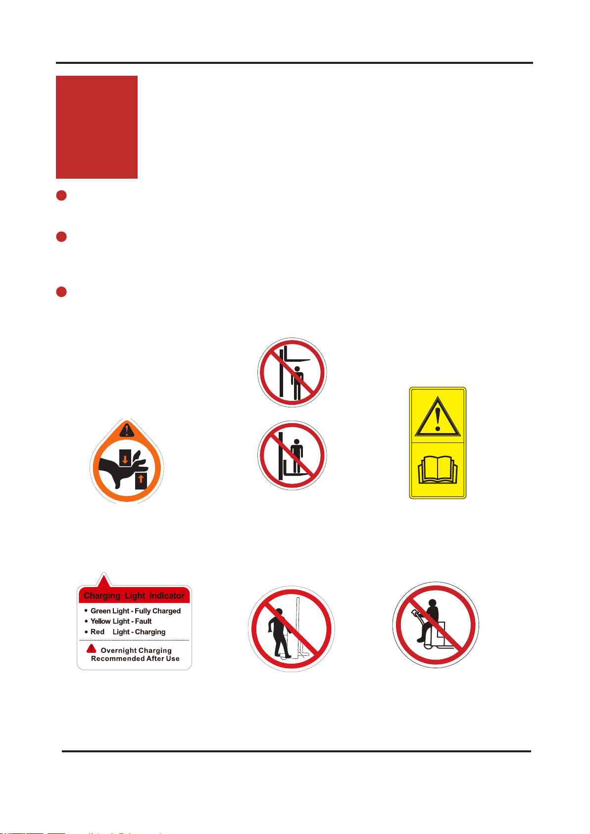
1.1 Utilization safety specication.............................................................................................B1
1.1.1 EN standards...................................................................................................................B2
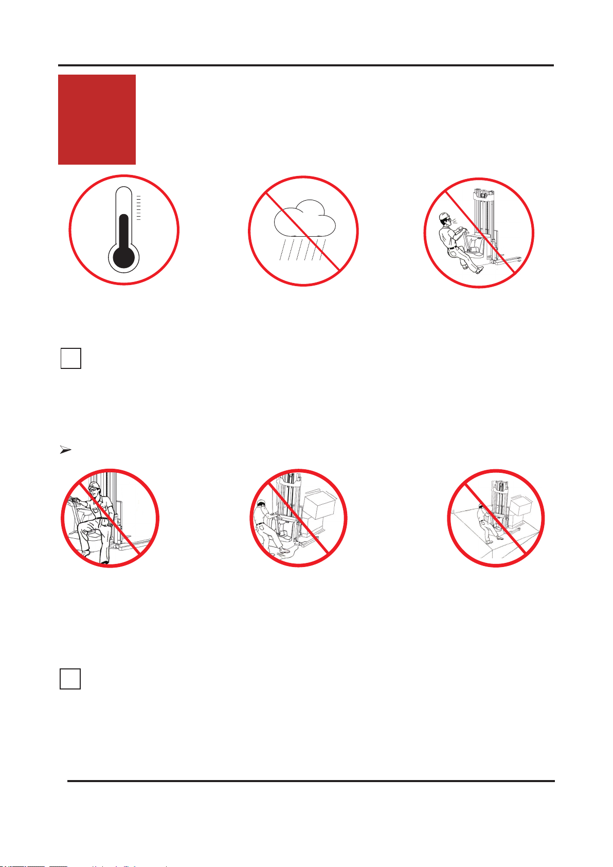
1.1.2 Conditions for application ...............................................................................................B3
1.1.3 Stability ...........................................................................................................................B3
2.2 Display and manipulation ...................................................................................................B4
2.2.1 Control handle .................................................................................................................B4
2.2.2 Key switch ......................................................................................................................B5
2.2.3 Display instrument...........................................................................................................B5
2.3 Truck use and operation.....................................................................................................B6
2.3.1 Preparation for use..........................................................................................................B6
2.3.2 Commissioning................................................................................................................B7
2.3.3 Truck starting ...................................................................................................................B8
2.3.4 Running, steerving and braking.......................................................................................B9
2.3.5 Goods picking................................................................................................................B12
2.3.6 Parking the truck securely .............................................................................................B14
2.3.7 Drive switch ...................................................................................................................B15
2.3.8 Loading..........................................................................................................................B15
2.3.9 Using the truck on a slope.............................................................................................B19
2.3.10 Operating the truck without its own drive system ........................................................B20
2.3.11 Transporting the truck ..................................................................................................B20
2.3.12 Hoisting........................................................................................................................B22
C Battery use and maintenance ..............................................................................................C1
1.1 Handling the battery ..........................................................................................................C1
1.1.1 Battery charging ..............................................................................................................C1
1.1.2 Battery type & dimensions&Charging time......................................................................C3
1.2 Battery removal and installation .........................................................................................C3
D Maintenance ........................................................................................................................D1
1.1 Truck maintenance .............................................................................................................D1
1.1.1 Safety announcement......................................................................................................D1
1.1.2 Decommissioning the industrial truck..............................................................................D1
1.1.3 Restoring the truck to operation ......................................................................................D1
1.1.4 Maintenance table ...........................................................................................................D2
1.2 Maintenance Instructions....................................................................................................D7
1.2.1 Checking the hydraulic oil level .......................................................................................D7
1.2.2 How to add oil..................................................................................................................D6
1.2.3 How to add grease or grease oil......................................................................................D8
1.2.4 Checking fuses................................................................................................................D8
1.2.5 Drive Wheel ...................................................................................................................D9
1.2.6 Load Wheels - Removal and Installation.......................................................................D10
1.2.7 Caster - Removal and Installation Removal ..................................................................D11
E Technical data .......................................................................................................................E1
Table of contents
Pg.

REV. 12/2020
1A
Identication points and data plates
A
Have the nameplates of a truck xed its main body and alarming labels pasted on its outer
cover.
Should any nameplate or alarming label lose or be damaged, please conduct replacement
immediately or contact with the sales department or corresponding agent of our company when
necessary.
Such truck-related information as product model, serial number, manufacturing date, rated
load lifting capacity, lifting height, load centre distance and dead weight are all shown in the
nameplates.
Instructions label
Anti-pinch hand label
Do not rest on the
stacker label
Notice “No standing under
the load carriage”label
Anti-pinch foot label
Charging indicator

REV. 12/2020 2A
Dmm
Hmm Q (kg)
The load capability chart
The capacity plate gives the capacity (Q) of
the truck in kg for a vertical mast.
The maximum capacity is shown as a table
with a given load centre of gravity D (in mm)
and the required lift height H (in mm).
The capacity plate of the truck indicates the
truck's capacity with the forks as originally
supplied.
Truck nameplate
For queries regarding the truck or ordering
spare parts please quote the truck serial
number.
Item Description
1TRUCK NAME
2MODEL TYPE
3SERIES NO.
4MANUFACTURE DATE
5UNLADEN MASS
6UNLADEN MASS
WITHOUT BATTERY
7BATTERY VOLTAGE
8RATED DRIVE
POWER
9MAX CAPACITY
10 MAX LIFT HEIGHT
11 RATED CAPACITY
12 LOAD CENTER
13 MAX BATTERY
WEIGHT
14 MIN BATTERY
WEIGHT
Fig0000-00012OM
Fig0000-00015OM
Emergency stop switch

REV. 12/2020
1
B
1.1 Utilization safety specication
The truck can by no means be used under the temperature lower than -10 °C for a long time, or
in refrigeratory or under the condition that such environmental factor as temperature or humidity
changes extremely before special equipment is additionally installed and the permit of the
manufacturer is acquired.
Operation
B
Don’t use the truck in
rainwater.
Don’t use the truck in non-
position.
Avoid the use of the truck by non-
working personnel.
Don’t ride on the truck.
Don’t carry or lift people by the
truck.
Don’t use the truck on slippery
road surfaces.
(such as road surfaces with oil
stain or residual snow or those
frozen ones )
Don’t carry goods on
steep slope to prevent
goods from sliding o.
Conditions of operation road surface: the truck should run on solid, at, level and paved road
surfaces (including both running and lifting)
i
NOTE
i
NOTE
Improper use
Fig0000-00016OM
Fig0000-00181OM
Applicable environment
temperature for lithium-ion
battery: -10 °C - 40 °C

REV. 12/2020 2B
Don’t place any part of
your body in any moving
part of the truck to avoid
being clamped.
Don’t leave the truck before
it is parked as regulated.
Don’t use the truck when any
non-working personnel is in the
dangerous area.
Don’t be distracted when using the
truck.
Don’t be distracted when using the
truck.
1.1.1 EN standards
Continuous sound level: 67 dB(A)
according to EN 12053 as stipulated in ISO 4871
The continuous sound level is a value averaged according to standard regulations, taking the
sound pressure level into account when driving, lifting and idling. The sound pressure level is
measured at the ear.
Electromagnetic compatibility (EMC)
The manufacturer confirms compliance with the limit values for electromagnetic emission and
interference immunity as well as testing of static electricity discharge according to EN 12895 and
the references to other standards contained therein.
Electrical or electronic components and their arrangement may only be modied after written
approval by the manufacturer has been obtained.
Fig0000-00182OM

REV. 12/2020
3
B
1.1.2 Conditions for application
Working condition requirements:
The walking, lifting and lowering devices, harness and components are IP55 dust and water-
resistant.
The truck's maximum operation altitude is up to 2000m.
Trucks can only be operated in adequately illuminated working areas to avoid injuries. In case
of insucient light, an additional lighting equipment is needed to ensure that the driver can see
properly.
If you must travel on an incline, the gradients should be below A% at full load, or below B% without
a load.(For the value of A and B, refer to the Gradability in technical data)
1.1.3 Stability
Stability is guaranteed if your truck is used properly in accordance with its intended
purpose. Common reasons for a loss of truck stability include:
Emergency stops or sharp turns.
Driving with a raised load or a load handling device.
Turning the vehicle around on or driving across a slope.
Driving up or down a slope with the load pointing downhill.
Driving with a wide load.
Carrying a swinging load.
Driving near the edge of a ramp or up steps.
Tilting the mast forward while carrying araised load.
Driving on uneven surfaces.
Overloading the truck.
Carrying bulky loads in strong winds.
When carrying liquid, its centre of mass inside the container may shift due to inertial force (such as
when pulling away, braking or turning).
Wind loads
Wind forces can aect the stability of a truck when lfting, lowering and transporting loads with large
surface areas .
Light loads must be especially secured when they are subjected to wind forces. This will prevent
the load from sliding or falling. Stop the truck in both cases .

REV. 12/2020 4B
2.2.1 Control handle
2.2 Display and manipulation
17 Lowering button Lower loading parts
18 Lifting button Lift loading parts
19 Drive switch Controls travel direction and speed
20 Horn button Send out sound warning signals
21 Emergency reverse swith Through touching the button, truck drives
away from operator.
Fig0000-00069OM

REV. 12/2020
5
B
1.Key switch
Connect and interrupt control current.
When the key rotates to gear “OFF”, the
control current of the truck will be interrupted;
When the key rotates to gear “ON”, the
control current of the truck will be connected.
2.2.2 Key switch
2.2.3 Display instrument
Fig0000-00070OM
• LED (1) displays the remaining charge;
• LED (2) displays the total running time
normally. If fault, display the fault code;
• LED (3) ashing, and the vehicle starts
timing;
• LED (4) is on, indicate vehicle failure;
• LED (5) is on under normal, it will ashing
when the power is less than 20%;

REV. 12/2020 6B
2.3 Truck use and operation
2.3.1 Preparation for use
The following are inspection and preparation operations that must be implemented before the
truck is put into daily use.
Daily Check Items O.K.(√) Remark
Check for Fluid Leakage
Check operation switch, display equipment
and component functions.
Check horn.
Check forward and reverse driving control
functions.
Check the function of the emergency brake
by activating the emergency stop switch.
Check lifting and lowering control functions.
Check emergency reverser function.
Check the battery installation, making
sure not to damage the battery cables.
Check the function of the steering funciton
Check the battery charging plug
Check the drive wheels and rollers for wear
and damage.
Check the hydraulic functions.
Check brake function of electromagnetic brakes.
Check whether optional functions are
operating normally.
WARNING
Table 1: Table of Daily Inspections by Operators is only a sample table for the daily inspections of
operators, and it can be adjusted according to specic requirements.
The truck should be regularly maintained by qualied maintenance engineers or technicians that
have passed the training of and also been authorized by the manufacturer.
WARNING

REV. 12/2020
7
B
The truck must only be operated on battery current!
To prepare the truck for operation after delivery or transportation, the following operations must be
performed:
Check the equipment for completeness.
If necessary, install the battery. Make sure that the battery cable is not damaged.
Charge the battery.
Check for Fluid Leakage.
Check the brake function.
Check the lifting and lowering function.
Check the driving function.
Check the steering function.
The truck can now be started, see 2.3.3 Truck starting
2.3.2 Commissioning
If the truck is delivered in multiple parts, setup and commissioning must only be
performed by trained, authorised personnel.
i
NOTE
Wheel attening
If the truck has been parked for a long period, the wheel surfaces may tend to
atten. This attening has a negative eect on the safety and stability of the truck.
Once the truck has covered a certain distance, the attening will disappear.

REV. 12/2020 8B
2.3.3 Truck starting
1. Release the emergency stop switch(1);
2.Turn the key switch (2) to start the truck;
3.Test the horn button(3);
The truck is now operational. Put the tiller in
the drive position(M) and use the drive switch
to control direction and speed.
1
2
3

REV. 12/2020
9
B
1.Running
Running area
2.3.4 Running, steering and braking
When using the truck on a ramp or a uneven road, please lift the mast to prevent its bottom from
colliding with the road surface.
i
NOTE
Tilt the control shaft into the running area (M) and control the running direction and speed of the
using the drive switch(1). (the lager the turning angle, the faster corresponding speed)
RV
R
V
B
M
B
i
NOTE
V is forwards.
R is reverse.
B is brake.
M is running area.
1

REV. 12/2020 10B
2.Steering
Turn the control handle (1) left or right
according to the desired direction.
3.Braking
Mechanical operating brake
The truck is braked when the operating
handle is released.
The mechanical brake engages when the tiller
is positioned in Braking area.
If the control handle moves slowly into the
brake position, identify the cause and rectify
the fault. If necessary, replace the gas spring!
CAUTION
B
B
1
1
2
Keep the handle in the vertical state,
and press tortoise speed button (1) and
drive switch(2) at the same time, then the
vehicle will move at a low speed.

REV. 12/2020
11
B
Emegency reverse switch
Braking can be accomplished by changing
the direction of travel.
Press the reverse switch in the opposite
direction until the truck comes to a stop,
then release the drive switch.
Emergency stop switch
Press the emergency stop switch, and then
all the electrically propelled functions will be
interrupted.
Regenerative braking
Release the drive switch. The drive switch will
automatically return to the initial position and
the vehicle will begin to enter the regenerative
braking state. When it decelerates
to <1 km/h, the electromagnetic brake will
bring the motor to a stop.
Open the drive switch; if the drive switch
cannot quickly return to the initial position
or resets very slowly, identify the cause and
rectify the fault.
CAUTION

REV. 12/2020 12B
2.3.5 Goods picking
1.Lifting
Keep pressing the lifting button until
reaching the required lifting height
2.Lowering
Lower the truck to the bottom through
pressing the lowering button.
Fig2108-00024OM
Fig2108-00025OM
Table of contents
Other ep Forklift manuals