Kongsberg Simrad HLD350 MK2 User manual

INSTRUCTION MANUA
L
Simrad HLD350 MK2
Simrad HLD2000 MK2L
Hydraulic Linear Drive

Note!
Simrad AS makes every effort to ensure that the information contained within this
document is correct. However, our equipment is continuously being improved and
updated, so we cannot assume liability for any errors which may occur.
Warning!
The equipment to which this manual applies must only be used for the purpose for which
it was designed. Improper use or maintenance may cause damage to the equipment or
injury to personnel. The user must be familiar with the contents of the appropriate
manuals before attempting to operate or work on the equipment.
Simrad AS disclaims any responsibility for damage or injury caused by improper
installation, use or maintenance of the equipment.
Copyright
© 2005 Simrad AS
The information contained within this document remains the sole property of Simrad AS.
No part of this document may be copied or reproduced in any form or by any means, and
the information contained within is not to be communicated to a third party, without the
prior written consent of Simrad AS.
www.simrad.com

Instruction manual
20220109E 1
Instruction Manual
This manual is intended as a reference guide for correctly installing
and maintaining the HLD350 MK2 and HLD2000 MK2 Hydraulic
Linear Drives.
Please take time to read this manual to get a thorough understanding of
the drive system components and its relationship to a complete autopilot
system.
Other documentation material that is provided with your system
includes a warranty card. This must be filled out by the authorized
dealer that performed the installation and mailed in to activate the
warranty.
Instruksjonsmanual
Denne manualen gir veiledning om installasjon og vedlikehold av de
hydrauliske drivenhetene HLD350 MK2 og HLD2000 MK2.
For å få en forståelse av drivenhetens virkemåte og funksjon i et
autopilotsystem bør manualen leses grundig.
Sammen med ditt system følger et garantikort. Dette må fylles ut av
installatør og sendes inn for at garantien skal være gyldig.

Simrad Hydraulic Linear Drive
2 20220109E
Document revisions
Documentation
department
Hardware/Software
design
Project/Product
Management
Rev Date Sign Date Sign Date Sign
– 07.97 N.G. 07.97 I.K. 07.97 Th.H.
A 29.04.98 N.G. 29.04.98 I.K. 29.04.98 Th.H.
B 21.09.99 N.G. 21.09.99 I.K. 21.09.99 Th.H.
C 15.11.00 N.G. 16.11.00 I.K. 16.11.00 Th.H.
D 19.02.03 N.G. 19.02.03 I.K. 19.02.03 Th.H.
E 16.02.05 16.02.05
Document history
Rev. – First edition
Rev. A New edition including MK2 versions
Rev. B Added measurement on figure 1. Adjusted figure 5.
Rev. C New environmentally friendly synthetic hydraulic oil, page 5, 6 and 7.
Corrected quantity for Pos.8 Bearing bush on fig. 11 from 1 to 2 and
description of P.N. 44165918 on page 23. Distributor list updated.
Rev. D New motors, type Lemac. Added colour on the o-ring at pos. 6, page 21
to avoid mix up. Minor corrections in text.
Rev. E Corrected part no. for RPU80 on page 19. Updated with new autopilot
computers.

Instruction manual
20220109E 3
Contents
1GENERAL..............................................................................................................5
2TECHNICAL SPECIFICATIONS.......................................................................7
2.1 Standard version .............................................................................................7
2.2 Split version....................................................................................................8
2.3 Dual cylinder version......................................................................................9
2.4 Comparison chart for HLD MK2 versions ...................................................10
3INSTALLATION .................................................................................................11
3.1 Mechanical installation.................................................................................11
3.2 Electrical connection ....................................................................................12
AC10/AC20 Autopilot Computer, J300X/J3000X Junction Unit ................12
J101A Junction Unit .....................................................................................12
4CONSTRUCTION AND PRINCIPLE OF OPERATION...............................15
4.1 Tank ..............................................................................................................15
4.2 Reversible Hydraulic Pump..........................................................................16
4.3 Hydraulic Rudder Cylinder ..........................................................................16
5PARTS LIST.........................................................................................................19
5.1 Linear drive units and main parts .................................................................19
5.2 Tank assembly ..............................................................................................20
5.3 Pump assembly .............................................................................................21
5.4 Cylinder assembly ........................................................................................22
6APPENDIX ...........................................................................................................24
6.1 Calculation of the force against the rudder...................................................24

Simrad Hydraulic Linear Drive
4 20220109E
Innhold
1 GENERELT............................................................................................................6
2 TEKNISKE SPESIFIKASJONER.......................................................................7
2.1 Delt versjon.....................................................................................................8
2.2 Dobbel sylinder versjon..................................................................................9
2.3 Sammenligningstabell for MK2 versjoner ...................................................10
3 INSTALLASJON .................................................................................................13
3.1 Mekanisk installasjon ...................................................................................13
3.2 Elektrisk tilkobling .......................................................................................14
AC10/AC20 autopilotcomputer/J300X/J3000X koblingsenhet ...................14
J101A koblingsenhet ....................................................................................14
4 KONSTRUKSJON OG VIRKEMÅTE .............................................................17
4.1 Tank ..............................................................................................................17
4.2 Reverserbar hydraulisk pumpe .....................................................................17
4.3 Hydraulisk rorsylinder..................................................................................18
5 PARTS LIST.........................................................................................................19
5.1 Linear drive units and main parts .................................................................19
5.2 Tank assembly ..............................................................................................20
5.3 Pump assembly .............................................................................................21
5.4 Cylinder assembly ........................................................................................22
6 TILLEGG .............................................................................................................26

Instruction manual
20220109E 5
1GENERAL
HLD350 MK2 and HLD2000 MK2 are hydraulic linear drives
designed for boats with mechanical steering systems such as wire and
cable steering (Edson, Whitlock, Teleflex).
The HLD is a compact, assembled unit, consisting of a reversible
hydraulic pump, a balanced hydraulic cylinder, by-pass valve and oil
tank.
Because of the direct connection to the rudder, the hydraulic linear
drive can be used even if the hand steering should fail. This can be an
important safety factor.
The by-pass valve makes it possible to use the helm with little back
drive force when the autopilot is switched off.
The HLD350 MK2 and HLD2000 MK2L supersede the previous
HLD350 and HLD2000L models. This manual also includes
HLD2000 MK2D. This model is based on the same main parts as
HLD350 MK2, but uses the HLD2000 MK2LD motor.
The MK2 versions were introduced in April 1998. The cylinder has a
slightly increased diameter and requires a modified piston assembly
and piston sealing. Otherwise the MK2 versions are identical to the
previous HLD350 and HLD2000L. The modified units have got a MK2
added to the type designation on the product label and applies from the
following serial numbers and onwards.
The basic specifications are:
Art. no. Ser. no. Description
21113303 545H36 HLD350 MK2 (200 mm stroke)
21113311 545H36 HLD350 MK2S (split version)
21113360 4154H69 HLD2000 MK2L (long version, 340 mm
stroke)
21113386 4154H610 HLD2000 MK2LS (long, split version)
21113345 3383H68 HLD2000 MK2D (dual cylinder version,
200 mm stroke)
21113402 4154H611 HLD2000 MK2LD (long dual cylinder
version)
In this manual HLD is used as a general term for all models. The MK2
designation is added only when specifically required for parts
identifications.
All HLD models are supplied with environmentally friendly synthetic
hydraulic oil with designation of type Hydralen 32 (viscosity 32 cSt).
This oil can without problem substitute/blend with ordinary hydraulic
oil with equivalent viscosity (between 15 and 40 cSt)

Simrad Hydraulic Linear Drive
6 20220109E
GENERELT
HLD350 MK2 og HLD2000 MK2 er hydrauliske lineære drivenheter
beregnet for båter med mekaniske styresystemer som kabel- og
wirestyring (Edson, Whitlock, Teleflex).
Den består av en kompakt sammenbygget enhet som inneholder
reverserbar hydraulisk pumpe, balansert hydraulisk sylinder, by-pass
ventil og oljetank.
På grunn av den direkte tilkoblingen til roret vil den lineære
drivenheten kunne brukes selv om håndstyringen skulle svikte, noe
som gir større sikkerhet.
Når autopiloten er avslått eller mister spenningen, vil by-pass ventilen
åpne slik at roret kan beveges uhindret ved hjelp av den mekaniske
styringen.
HLD350 MK2 og HLD2000 MK2L etterfølger de tidligere modellene
HLD350 og HLD2000L. Manualen omhandler også HLD2000
MK2D. Denne modellen baserer seg på samme hoveddeler som
HLD350 MK2, men bruker samme motor som HLD2000 MK2LD.
MK2 versjonen ble introdusert i april 1998. Sylinderen har en noe
større diameter og krever et modifisert stempel og stempelforing.
Ellers er MK2 versjonene identiske med HLD350 og HLD2000L.
Modifiserte enheter har fått tilføyd MK2 på produktmerkelappen og
modifikasjonen er gjort gjeldende fra følgende serienummer:
Art. nr. Ser. nr. Beskrivelse
21113303 545H36 HLD350 MK2 (200 mm slaglengde)
21113311 545H36 HLD350 MK2S (delt utgave)
21113360 4154H69 HLD2000 MK2L (lang utgave, 340 mm
slaglengde)
21113386 4154H610 HLD2000 MK2LS (lang, delt utgave)
21113345 3383H68 HLD2000 MK2D (dobbel sylinder,
200 mm slaglengde)
21113402 4154H611 HLD2000 MK2LD (lang, dobbel sylinder)
I denne manualen brukes HLD som en generell betegnelse for alle
modeller. MK2 er kun brukt når det er behov for å identifisere deler.
Alle HLD modeller leveres med en syntetisk, miljøvennlig
hydraulikkolje av typen Hydralen 32 (Viskositet 32 cSt). Denne oljen
kan uten problem erstatte/blandes med vanlig hydrolikkolje med
tilsvarende viskositet (mellom 15 og 40 cSt).

Instruction manual
20220109E 7
2TECHNICAL SPECIFICATIONS
2.1 Standard version
Motor voltage:................................12V DC
Max. current HLD350/2000L: .......10/20A
Average power consumption: ........40 – 60 W
Peak thrust HLD350/2000L: ..........350kp / 500kp
Continuous duty HLD350/2000L: .250kp / 390kp
Max. speed HLD350/2000L: .........10 sec./17 sec. full travel
(Adjustable in the autopilot
electronics)
Stroke: ............................................200mm / 340mm
Overall length with piston in
middle position:.............................. 578mm / 858mm
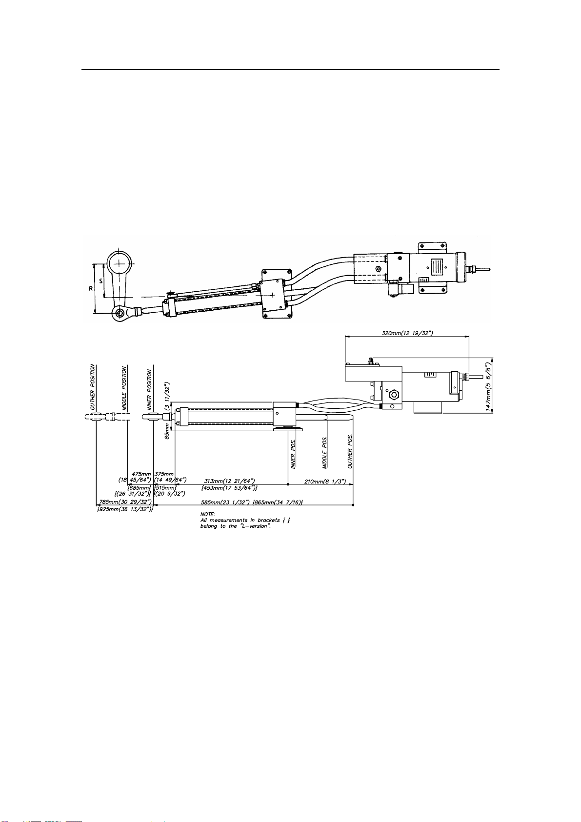
Dimensions:.................................... See fig. 1
Hydraulic oil: .............Hydralen 32, High quality environmentally
friendly, synthetic hydraulic oil.
Alternative oil: ........... Norol HM32, Shell Tellus 27, Esso HP15 and
Yukong Supervis AW32/X32.)
Viscosity 15-40 cSt at 40°C.
Figure 1 HLD dimensions (shown with Fracmo motor)
{350mm (13 ¾”)}
Simrad Hydraulic Linear Drive
8 20220109E
2.2 Split version
To obtain good flexibility in the installation of the HLD, a split
version is available.
The hydraulic cylinder and the motor/pump-unit are made as separate
units with provisions to connect hydraulic hoses between the two.
Modifications have been made on the pump housing for this purpose.
The split version is available with standard (200 mm) or long stroke
(340 mm) and with hose lengths of 1 m (3 ft).
Figure 2 HLD Split version (Shown with Fracmo type motor)
For å oppnå best mulig fleksibilitet ved installasjon er enheten
tilgjengelig i delt utgave.
Hydraulisk sylinder og motor/pumpeenhet er laget som separate
enheter for sammenkobling ved hjelp av hydraulikk-slanger. I denne
forbindelse er det gjort små modifikasjoner på de to enhetene.
Delt utgave kan leveres både med standard slaglengde (200 mm)og
med lang slaglengde (340 mm), og med slanger på 1,0 m.

Instruction manual
20220109E 9
2.3 Dual cylinder version
This model meets the requirement for increased torque without
increasing the radial forces on the rudder stock.
It combines a powerful reversible pump (RPU300) with two cylinders
having the standard stroke or long stroke. 4 flexible hoses of 1 m (3 ft)
connect the pump to the cylinders.
By connecting the cylinders as shown, the radial forces are balanced
out, whilst a double torque has been achieved.
The dual cylinder version is for 24V DC operation only.
Figure 3 HLD Dual cylinder (Shown with Fracmo type motor)
Denne utgaven med doble sylindere er utviklet for å øke dreie-
momentet uten å øke de radielle kreftene som virker på rorstammen.
Den kombinerer en kraftigere reverserbar pumpe (RPU300), med to
sylindere med standard slaglengde, eventuelt med lang slaglengde. 4
oljeslanger på 1 m forbinder pumpen med sylindrene. Ved å montere
sylindrene som vist på figuren får man balansert de radielle kreftene,
samtidig som dobbelt dreiemoment oppnås.
Den doble sylinderversjonen er kun beregnet for 24V DC.

Simrad Hydraulic Linear Drive
10 20220109E
2.4 Comparison chart for HLD MK2 versions
MODEL MOTOR
VOLTS
AUTOPILOT
COMPUTER/
JUNCTION
UNIT
MAX
STROKE
mm (in.)
PEAK
THRUST
kg (lb.)
MAX
RUDDER
TORQUE
Nm
(lb.in.)
HARD-
OVER
TIME
sec.
(30% load)
PWR.
CON-
SUMP.
TILLER
ARM
mm
(in.)
HLD350
HLD350S
12V AC10,
J3000X
200 (7,9) 350
(770)
610
(5400)
12 3,5-10 A 175
(6,9)
HLD2000L
HLD2000LS
12V AC20,
J300X
340 (13,4) 500
(1100)
1460
(12850)
12 5-16 A 298
(11,7)
HLD2000D 24V AC20,
J300X
200 (7,9) 1050
(2310)
1800
(15900)
9 5-16 A 175
(6,9)
HLD2000LD 24V AC20,
J300X
340 (13,4) 1050
(2310)
3180
(28000)
15 5-16 A 298
(11,7)
Steeringgearinterface:Connectstoquadrantortiller.
1. The autopilot computer/junction unit steps down the motor voltage
when operating from 24V or 32V mains.
2. The specified computer/junction unit is necessary to achieve max
drive unit capacity.
3. Recommended operational thrust or torque is 70% of listed value.
4. Typical average power consumption is 40% of listed maximum
value.
Rortilkobling: Kobles til kvadrant eller rorkult.
1. Autopilotcomputeren/koblingsenheten regulerer ned
motorspenningen ved 24V eller 32V nettspenning.
2. Spesifisert computer/koblingsenhet er nødvendig for å oppnå
maksimal kapasitet fra drivenhet.
3. Anbefalt skyvkraft eller moment ved drift er 70% av oppgitt verdi.
4. Gjennomsnittlig effektforbruk er typisk 40% av oppgitt
maksimumsverdi.

Instruction manual
20220109E 11
Fi
g
ure 4 HLD350 Installation dia
g
ram Fi
g
ure 5 HLD2000L Installation dia
g
ram
3INSTALLATION
Refer to table in section 2.4 to verify that appropriate HLD model is
selected for your boat.
If there is any doubt as to whether HLD350/HLD2000L can be
installed, this can be clarified by undertaking the calculations shown
in the appendix.
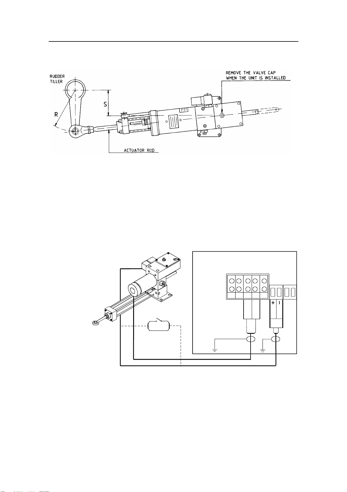
3.1 Mechanical installation
Rudder and actuator rod is set to midposition. To obtain maximum
and smooth thrust over the actuator's complete stroke, the HLD should
be installed in accordance with fig. 6. The distances R and S for
different rudder angles are found in the diagram in fig. 4 and 5.
The HLD should be fitted with the enclosed safety connector between
actuator and tiller to ensure quick disconnection in emergency
situations.
Note ! Drill and tap the rudder tiller (M12x1.75) to secure the bolt firmly.
Caution ! Do never install the unit upside down! (The air valve should be
facing upwards.) The HLD must be installed horizontally only. No
more than
±
5 degrees tilt is allowed at any position, as illustrated on
figure 1. The HLD should not act as an end stop for the rudder.
8
10
12
14
16
18
20
22
24
25 30 35 40 45
cm
R
S
RUDDER ANGLE / RORVINKEL
50 55 60
DISTANCE R AND S
AVSTAND R OG S
DEGREES
GRADER
8
12
16
20
24
28
32
36
40
25 30 35 40 45
cm
R
S
RUDDER ANGLE / RORVINKEL
50 55 60
DISTANCE R AND S
AVSTAND R OG S
DEGREES
GRADER
Simrad Hydraulic Linear Drive
12 20220109E
Remove the valve cap on the tank when the unit is installed.
Figure 6 HLD Installation
3.2 Electrical connection
AC10/AC20 Autopilot Computer,
J300X/J3000X Junction Unit
The HLD is connected to the autopilot via AC10, AC20, J300X or
J3000X according to the following diagram:
POWER PCB
TB1 TB2 TB3 TB4 TB5
TB6
Drive
Engage
Sol. -Motor
Sol. -Motor
TB7
HYDRAULIC
LINEAR DRIVE
Single pole
clutch/bypass
switch
Figure 7 HLD connection to ACXX and J3XX
J101A Junction Unit
The HLD can also be connected to previous models autopilots using
the J45A, J101A or J1000 Junction units. The Junction Unit controls
the current to the motor and the bypass valve. The Junction Unit also
has built-in speed regulation of the HLD, which allows rudder speed

Instruction manual
20220109E 13
adjustment (i.e. the steering performance of the boat when autopilot
steering) after installation of the system.
Note that for the HLD350 (not the HLD2000L) the trim potentiometer
RV1 in J1000/J101A/J45A should be adjusted to approx. 2/3 of full
C.W. position.
The J1000/J101A/J45A also has a built-in current limiter to prevent
overload of the motor (Max. current is 20A).
Motor/bypass connection
The bypass valve is connected to terminal 13 and 14 in
J45A/J101A/J1000, and is polarity independent.
The motor is connected to terminal A and B in J45A/J101A/J1000.
Interchange of A and B will change the direction of rotation.
Cable for the motor supply voltage from the ship mains must be at
least 2x4mm2(AWG10), and fused according to the table enclosed
with the J101A/J1000.
INSTALLASJON
Kontroller mot tabellen under seksjon 2.4 at riktig HLD model er
valgt.
Er det tvil om hvorvidt HLD350 eller HLD2000L skal velges, kan
dette klargjøres ut fra beregningene som er vist i tillegget bak i
manualen.
Mekanisk installasjon
Plasser stempelstang og ror i midtstilling. HLD monteres slik fig. 6
viser for å få maksimal skyvkraft langs hele stempelstangens
vandring. Avstandene R og S ved de forskjellige rorvinkler finnes i
diagram fig. 4 og 5.
HLD er utstyrt med hurtigkopling mellom stempelstang og rorkult
som tillater hurtig frakobling i nødssituasjoner.
Bruk M12x1,75 gjengetapp og gjeng opp i rorkult.
HLD må aldri monteres opp ned! (Lufteventil på tank skal peke
oppover). Enheten må monteres horisontalt, og slik at avviket fra
horisontalplanet aldri overstiger ±5 grader, slik som illustrert på
fig. 1. HLD må ikke monteres slik at den fungerer som endestopp
for roret.
Husk å skru av ventilhetten på tanken etter at enheten er montert.

Simrad Hydraulic Linear Drive
14 20220109E
Elektrisk tilkobling
AC10/AC20 autopilotcomputer,
J300X/J3000X koblingsenhet
HLD kobles til autopiloten via AC10, AC20, J300X eller J3000X i
henhold til fig. 7.
J101A koblingsenhet
HLD kan også kobles til tidligere autopilotmodeller som bruker
J101A eller J1000 koblingsenheter. Koblingsenhetene kontrollerer
strømmen til motoren og by-pass ventilen. Koblingsenheten har også
innebygget hastighetsregulering av HLD, noe som gir anledning til å
justere rorhastighet (og dermed båtens styreegenskaper med autopilot)
etter at systemet er installert.
Ved bruk av HLD350 (gjelder ikke HLD2000L) bør trimme-
potensiometer RV1 i J45A/J101A/J1000settes til ca. 2/3 av fullt
område.
I J45A/J101A/J1000er det også innebygget en strømbegrenser som
hindrer overbelastning av motor (maks. strøm er 20A).
Kobling av motor/bypassventil:
Bypassventil kobles til terminal 13 og 14 i J45A/J101A/J1000 og er
polaritetsuavhengig.
Motoren kobles til terminal A og B i J45A/J101A/J1000. Ombytting
av A og B vil snu motorens dreieretning.
Kabel for motorspenning fra båtens fordelingsskap må være minst
2x4mm2og sikret i.h.h.t. tabell vedlagt i J45A/J101A/J1000.

Instruction manual
20220109E 15
4CONSTRUCTION AND PRINCIPLE OF
OPERATION
The HLD is delivered completely assembled with tank, reversible
hydraulic pump and a balanced hydraulic cylinder. The HLD is
therefore a completely closed system.
4.1 Tank
The tank is machined out of
solid aluminium and all
necessary oil ways are
drilled out.
A bypass valve is mounted
in the tank, to allow the
mechanical steering system
to be used, when the
autopilot is not in operation.
The bypass valve is a
standard ON/OFF solenoid
valve, normally open.
When the autopilot is in
STBY mode, the solenoid
valve will be in open
position.
When AUTO or NAV mode
is selected, the solenoid
valve will be in closed
position.
The solenoid valve opens
immediately when the
autopilot is switched off, and
handsteering is allowed.
Previous versions
An early version of HLD350
and HLD350S did not have
check valves. The following
serial no. codes can identify it:
H30 (HLD350) and H31 (HLD350S).
The principle of operation was similar to that of HLD2000L. The
(suction) valves, however, operated as combined suction and (non-
return) check valves controlled by internal pressure and direction of oil
flow. The resulting effect was a smoother check valve operation as
Functional diagram
1. Electrical motor (Elektromotor)
2. Gear pump (Tannhjulspumpe)
3. Suction valve (Innsugingsventil)
4. Check valve (Tilbakeslagsventil)
5. Oil tank (Oljetank)
6. By-pass valve (By-pass ventil)
7. Hydraulic actuator (Hydraulisk
sylinder)
7
6
M
44
33
2
1
5

Simrad Hydraulic Linear Drive
16 20220109E
compared to the ones with separate check valves. It should be observed
however, that this version does not have the extra protection against
internal leakage (bypass) as the models with separate check valves.
4.2 Reversible Hydraulic Pump
The pump consists of valve block, reversible gear pump, pressure
operated check (non-return) valves, electric permanent magnet motor,
suction valves and slide.
The pump is reversible, i.e. the motor changes direction of rotation
and the gear pump delivers oil to that side of the rudder cylinder
dictated by the signal from the autopilot. When the motor is running,
the pressurised (or delivery) side will hold both check valves open,
using direct oil pressure upon the valve on the delivery side. This oil
pressure is also used to push a slide to open the valve on the suction
side.
When the motor stops, the spring in the check valve on the suction
side returns the slide to the neutral position. Both check valves are
now closed and the rudder cylinder locked. Both sides of the gear
pump are able to suck oil from the tank through the suction valves.
4.3 Hydraulic Rudder Cylinder
The rudder cylinder consists of the cylinder itself, actuator, actuator
rod, ball joint and base plate.
The actuator rod runs through the cylinder. The actuator area is
identical on both sides, and this balances the cylinder.
Figure 8 HLD Assembly drawing (N3-111832)
(Shown with Fracmo type motor)

Instruction manual
20220109E 17
KONSTRUKSJON OG VIRKEMÅTE
HLD leveres komplett sammenbygget med tank, reverserbar
hydraulisk pumpe og balansert hydraulisk sylinder. Den arbeider
dermed i et lukket system.
Tank
Tanken er frest ut av massiv aluminium og nødvendige oljeløp er
utboret.
I tanken er det montert en bypass-ventil for at det mekaniske
styresystemet skal kunne brukes når autopiloten ikke er i bruk.
Bypass-ventilen er en standard Av/På magnetventil som normalt er
åpen.
Magnetventilen er åpen når autopiloten er i STBY og lukket når
autopiloten er i AUTO eller NAV. Ventilen åpner umiddelbart når
autopiloten slås av slik at håndstyring kan benyttes.
Tidligere versjoner
En tidligere versjon av HLD350 og HLD350S har ikke
tilbakeslagsventil. Denne versjonen identifiseres med følgende serie
nr. kode: H30 (HLD350) og H31 (HLD350S).
Betjeningsprinsippet var tilsvarende som for HLD2000L.
Innsugnings-ventilene fungerte imidlertid som kombinerte innsugings-
og tilbakeslagsventiler kontrollert av det interne trykket og retningen
av oljestrømmen. Effekten av dette var en jevnere sperrefunksjon
sammenlignet med enheter med egen tilbakeslagsventil. Denne
versjonen gir imidlertid ikke den ekstra beskyttelse mot intern
lekkasje som den med egen tilbakeslagsventil gir.
Reverserbar hydraulisk pumpe
Pumpen består av ventilblokk, pumpeenhet, motor med permanente
magneter, tilbakeslagsventiler og sleide.
Pumpen er reverserbar, dvs. at motoren kan endre dreieretning og
tannhjulspumpen vil levere oljen enten til den ene eller andre enden av
rorsylinderen, avhengig av signalene fra autopiloten.
Når motoren går, vil pumpens trykkside holde begge de trykkstyrte
tilbakeslagsventilene åpne. Tilbakeslagsventilen på trykksiden åpnes
direkte av oljetrykket, mens den på sugesiden blir åpnet av en sleide
som skyves over av oljetrykket på trykksiden.
Når signalet fra piloten opphører, vil fjæren i tilbakeslagsventilen på
sugesiden trykke sleiden tilbake til nøytralstilling. Begge
tilbakeslagsventilene vil da være lukket. Den hydrauliske sylinderen

Simrad Hydraulic Linear Drive
18 20220109E
er dermed låst. Begge sider av tannhjulspumpen kan suge fra tank via
innsugningsventiler.
Hydraulisk rorsylinder
Rorsylinderen består av sylinderrør, stempelstang med stempel,
endestykke og fot.
Stempelstangen er gjennomgående. Stempelarealet er likt på begge
sider, og sylinderen er dermed balansert.
This manual suits for next models
1
Table of contents
Popular DC Drive manuals by other brands


gefran
gefran EXP-D20A6 instruction manual

REXROTH
REXROTH IndraDrive Project planning manual

gefran
gefran ADV200 WA Quick start up guide, Specification and installation

YASKAWA
YASKAWA CIMR-JB Series Installation & start-up manual

GE
GE Fuji Electric AF-300ES instructions

SOMFY
SOMFY Sonesse Ultra 50 instructions


