Unimotion STDF PD User manual

Manual
Closed Loop Stepping System Manual
STDF PD - Pulse-direction


3/24
TABLE OF CONTENTS
1Before operation 4
1.1 Precautions ............................................................................................................ 4
1.1.1 Put the Safety First ..................................................................................................... 4
1.1.2 Operation..................................................................................................................... 5
1.1.3 Check and Repair ........................................................................................................ 5
2Drive Specification and Dimension 6
2.1 Specifications of Drive............................................................................................ 6
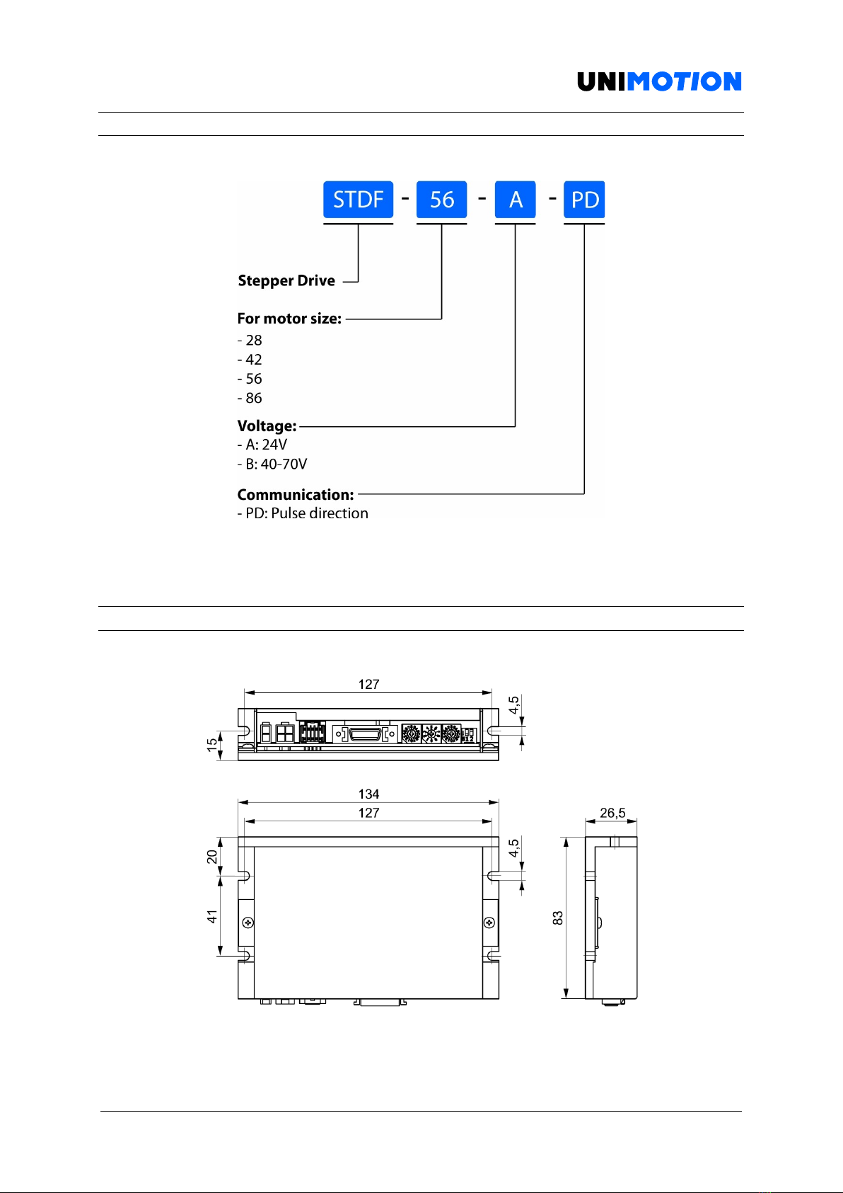
2.2 Model naming......................................................................................................... 7
2.3 Product dimensions................................................................................................ 7
3Installation 8
3.1 Precautions of installation ...................................................................................... 8
3.2 Appearance and part name ..................................................................................... 8
4Brake Operation Timing Chart 9
5Settings and Operation 10
5.1 Drive Status LED ................................................................................................... 10
5.2 Pulse Input Setting Switch (SW1.1) ....................................................................... 11
5.3 Rotational Direction Setting Switch (SW1.2) .......................................................... 12
5.4 Resolution Setting Switch (SW3)........................................................................... 12
5.5 Position Controller Gain Setting Switch (SW2)....................................................... 13
5.6 In-Position Value Setting Switch (SW4)................................................................. 14
5.7 Encoder Connector (CN2) ..................................................................................... 15
5.8 Input/Output Signal Connector (CN1) .................................................................... 15
5.9 Motor Connector (CN3)......................................................................................... 16
5.10 Power Connector (CN4)..................................................................................... 16
6System Configuration 17
6.1 External Wiring Diagram........................................................................................ 18
7Control Signal Input/Output Description 19
7.1 Input Signal .......................................................................................................... 19
7.2 CW, CCW Input ..................................................................................................... 19
7.3 Servo On/Off Input................................................................................................ 20
7.4 Alarm Reset Input ................................................................................................. 20
7.5 Output signal ........................................................................................................ 21
7.6 Alarm Output ........................................................................................................ 21
7.7 In-Position Output ................................................................................................ 22
7.8 Encoder Signal Output .......................................................................................... 22

4/24
1 BEFORE OPERATION
Thank you for your purchasing the STDF PD drive.
STDF PD is an all-in-one unit. For the high-speed and high-precision drive of a stepping motor,
STDF PD is a unique drive that adopts a new control scheme owing to an onboard
high-performance 32-bit MCU.
This manual describes handling, maintenance, repair, diagnosis and troubleshooting of the
STDF PD.
Before operating with STDF PD, thoroughly read this manual.
After reading the manual, keep the manual near the STDF PD so that any user can read it
whenever required.
1.1 Precautions
1.1.1 Put the Safety First
Before installation, operation and repairing the STDF PD, thoroughly read the manual and
fully understand the contents. Before operating the STDF PD please, understand the
mechanical characteristics of the STDF PD and related safety information and precautions.
This manual divides safety precautions into Attention and Warning.
Attention
If the user does not properly handle the product, the user may seriously or slightly be injured
and damages may occur in the machine.
Warning
If the user does not properly handle the product, a dangerous situation (such as an electric
shock) may occur resulting in deaths or serious injuries.
Although precaution is only an Attention, a serious result could be caused depending on the
situation.
Follow safety precautions.

5/24
1.1.2 Operation
Attention
If a protection function (alarm) occurs, firstly remove its cause and then release (alarm reset)
the protection function. If you operate continuously without removing its cause, the machine
may get damaged or the user may get injured.
Do not make Motor Free and make input signal to ON during operation. The motor will stop
and the stop current will become zero. The machine may get damaged or the user may get
injured.
Make all input signals OFF before supply input voltage to STDF PD. The machine may get
damaged or the user may get injured by motor operation.
All parameter values are set by default factory setting value. Change this value after reading
this manual thoroughly. Otherwise, the machine may get damaged or other kinds of accidents
may occur.
1.1.3 Check and Repair
Attention
Stop to supply power to the main circuit and wait for a while before checking or repairing the
STDF PD. Electricity remaining in the capacitor may cause danger.
Do not change cabling while power is being supplied. Otherwise, the user may get injured or
the product may get damaged.
Do not reconstruct the STDF PD. Otherwise, an electric shock may occur or the reconstructed
product can not get After-Service.

6/24
2 DRIVE SPECIFICATION AND DIMENSION
2.1 Specifications of Drive
Table 2-1: Drive specifications.
Input Voltage
24 V DC +/- 10%
Control Method
Closed loop control with 32-bit MCU
Current Consuption
Max 500 mA (Except the motor current)
Operating Condition
Ambient temperature
In Use: 0 ∼50 °C
In Storage: –20 ∼70 °C
Humidity
In Use: 35 –85 % RH (Non–
condensing)
In Storage: 10 –90 % RH (Non–
condensing)
Vib. Resist.
0.5 G
Function
Rotation Speed
0 ∼3000
Resolution [ppr]
500, 1000, 1600, 2000, 3600, 5000,
6400, 7200, 10000 (Selectable with
the rotary switch)1
Max. Input Pulse Frequency
500 kHz (Duty 50 %)
Protection Functions
Over Current Error, Over Speed
Error, Position Tracking Error,
Encoder Connect Error, In-Position
Error, System Error, ROM Error,
Position Overflow Error
LED Display
Power status, In-Position status,
Servo On status, Alarm status
In-Position Selection
0 –F (Selectable with Rotary
switch)
Position Gain Selection
0 –F (Selectable with Rotary
switch)
Pulse Input Method
1 –Pulse/2 –Pulse (Selectable
with DIP switch)
Rotational Direction
CW/CCW (Selectable with DIP
switch)
Speed/Position Control
Command
Pulse-Train Input
I/O Signal
Input Signals
Position Command Pulse, Servo
On/Off, Alarm Reset (Photocoupler
Input)
Output Signals
In-Position, Alarm (Photocoupler
Input) Encoder Signal (A+, A-, B+, B-,
Z+, Z-, 26C31 of Equivalent) (Line
Driver Output), Brake
1 When selected resolution is more than encoders resolution, motor shall operate by microstep between pulses.

7/24
2.2 Model naming
Figure 2-1: Model naming.
2.3 Product dimensions
Figure 2-2: Dimensions of the STDF PD drive.

8/24
3 INSTALLATION
3.1 Precautions of installation
1. STDF PD is designed for indoor use only.
2. The ambient temperature of the room should be 0 °C ∼50 °C.
3. If the temperature of the product case is higher than 50 °C, radiate heat of the
outside to cool down.
4. Do not install STDF PD under direct rays, near magnetic or radioactive objects.
5. If you set more than 2 drives, you must set over 20 mm vertically and over 50 mm
horizontally as shown below.
Figure 3-1: Installation dimensions for 2 or more drives.
3.2 Appearance and part name
Figure 3-2: Appearance of the STDF PD drive.

9/24
4 BRAKE OPERATION TIMING CHART
STDF PD controls Brake by Drive automatically.
Please refer to below Timing Chart when Brake is controlled by the upper controller other
than using STDF PD Brake control. Otherwise, Drive malfunctioning and loads can be fall
down.
Also, please do not operate Brake while motor operation to prevent damage.
Figure 4-1: Brake operation timing chart.

10/24
5 SETTINGS AND OPERATION
5.1 Drive Status LED
Table 5-1: Drive status LED indication.
Indication
Color
Function
ON/OFF Condition
PWR
Green
Power indication
LED is turned On
when power is
applied
INP
Yellow
Complete
Positioning Motion
Lights On when
Positioning error
reaches within the
preset pulse
selected by rotary
switch
SON
Orange
Servo On/Off
Indication
Servo On: Lights On
Servo Off: Lights Off
ALM
Red
Alarm Indication
Flash when
protection function
is activated
(Identifiable which
protection mode is
activated by
counting the
blinking times)
Figure 5-1: Alarm LED flashing cycle

11/24
Table 5-2: Protection functions and LED flash times.
Times
Protection
Conditions
1
Over Current Error
The current through power devices if inverter
exceeds the limit value of 4.8 A.
2
Over Speed Error
Motor speed exceeds 3000 rpm.
3
Position Tracking Error
Position error value is higher than 180°in motor
run state.
4
Over Load Error
The motor is continuously operated more than 5
seconds under a load exceeding the max.
Torque.
5
Over Temperature Error
Inside temperature of drive exceeds 85 °C.
6
Over Regenerative Voltage
Error
Back-EMF is higher than limit value.
7
Motor Connect Error
The power is ON without connection of the
motor cable to drive.
8
Encoder Connect Error
Cable connection error in Encoder connection of
drive.
10
In-Position Error
After operation is finished, position error more
than 1 pulse is continued for more than 3
seconds.
11
System Error
Error occurs in drive system.
12
ROM Error
Error occurs in parameter storage device (ROM).
15
Position Overflow Error
Position error value is higher than 180° in motor
stop state.
5.2 Pulse Input Setting Switch (SW1.1)
Indication
Switch Name
Functions
2P/1P
Selecting Pulse
Input Mode
Selectable 1-Pulse input mode or 2-Pulse
input mode as Pulse input signal ON: 1-
Pulse mode OFF: 2-Pulse mode (Default:
2-Pulse mode)
Figure 5-2: Pulse input setting switch.

12/24
5.3 Rotational Direction Setting Switch (SW1.2)
Table 5-3: Rotational direction setting switch function.
Indication
Switch Name
Function
DIR
Switching Rotational
Direction
Based on CW (+DIR signal) input to driver.
Figure 5-3: Rotation direction setting.
5.4 Resolution Setting Switch (SW3)
Table 5-4: Number of pulses per revolution.
Position
Pulse/Revolution
0
5001
1
500
2
1000
3
1600
4
2000
5
3600
6
5000
7
6400
8
7200
9
10000
1Resolution of position “0” will be different according to the resolution of encoder adopted to the product. But in case
of the encoder with 10,000 ppr resolution, it will be set as 500.
When selected resolution is more then encoder resolution, motor shall be operated by microstep between pulses.

13/24
5.5 Position Controller Gain Setting Switch (SW2)
The Position Controller Gain Switch allows for the correction of the motor position deviation
after stopping caused by load and friction. Depending on the motor load, the user may have
to select a different gain position to stabilize and to correct positional error quickly.
To tune the controller:
1. Set the switch to “0” position.
2. Start to rotate the switch until system becomes stable.
3. Rotate the switch 1~2 position to reach better performance.
Table 5-5: Position controller time constant and gain values.
Position
Time Constant of
the integral par
Proportional
Gain1
0
1
1
1
1
2
2
1
3
32
1
4
4
1
5
5
2
1
6
2
2
7
2
3
8
2
4
9
2
5
A
3
1
B
3
2
C
3
3
D
3
4
E
3
5
F
3
6
1Value in the columns are in relative units. They only show the parameter changes depending on the switch’s position.
2Default = 3

14/24
5.6 In-Position Value Setting Switch (SW4)
To select the output condition of In-Position signal, In-Position output signal is generated
when the pulse number of positional error is lower than selected In-Position value set by this
switch after positioning command is executed.
Table 5-6: In-Position values.
Position
In-Position Value [Pulse]
Fast Response
01
0
1
1
2
2
3
3
4
4
5
5
6
6
7
7
8
0
9
1
A
2
B
3
C
4
D
5
E
6
F
7
1Default = 0
Figure 5-4: Setting method of Fast Response and Accurate Response.

15/24
5.7 Encoder Connector (CN2)
Table 5-7: Encoder connector signals.
NO.
Function
I/O
1
A+
Input
2
A-
Input
3
B+
Input
4
B-
Input
5
Z+
Input
6
Z-
Input
7
5 V DC
Output
8
GND
Output
9
F.GND
----
10
F.GND
----
5.8 Input/Output Signal Connector (CN1)
Table 5-8: I/O Connector signals.
NO.
Function
I/O
1
CW+ (Pulse+)
Input
2
CW- (Pulse-)
Input
3
CCW+ (Dir+)
Input
4
CCW- (Dir-)
Input
5
A+
Output
6
A-
Output
7
B+
Output
8
B-
Output
9
Z+
Output
10
Z-
Output
11
Alarm
Output
12
In-Position
Output
13
Servo On/Off
Input
14
Alarm Reset
Input
15
Open collector input
Input
16
BRAKE+
Output
17
BRAKE-
Output
18
S-GND
Output
19
EXT_GND
Input
20
EXT_24 V DC
Input
Figure 5-6: I/O Connector.
Figure 5-5: Encoder Connector.

16/24
5.9 Motor Connector (CN3)
Table 5-9: Motor Connector signals.
NO.
Function
I/O
1
A Phase
Output
2
B Phase
Output
3
/A Phase
Output
4
/B Phase
Output
5.10 Power Connector (CN4)
Table 5-10: Powe Connector signals.
NO.
Function
I/O
1
24 V DC
Input
2
GND
Input
Figure 5-7: Motor Connector.
Figure 5-8: Power Connector.

17/24
6 SYSTEM CONFIGURATION
Figure 6-1: System configuration.

18/24
6.1 External Wiring Diagram
Figure 6-2: External wiring diagram.

19/24
7 CONTROL SIGNAL INPUT/OUTPUT DESCRIPTION
7.1 Input Signal
Input signals of the drive are all photocoupler protected. The signal shows the status of
internal photocouplers [ON: conduction], [OFF: Non-conduction], not displaying the voltage
levels of the signal.
7.2 CW, CCW Input
Table 7-1: CW and CCW input functions..
Pin No.
Function
1
CW+
2
CW-
3
CCW+
4
CCW-
Figure 7-1: CW and CCW wiring diagram.
This signal can be used to receive a positioning pulse command from a user’s host motion
controller. The user can select 1-pulse input mode or 2-pulse input mode. The input
schematic of CW, CCW is designed for 5 V TTL level. When using 5 V level as an input signal,
the resistor Rx is not used and connected to the drive directly.
When the level of input signal is more than 5 V, Rx resistor is required. If the resistor is absent,
the drive can be damaged In the case input signal level is 12 V, Rx value is 680 Ωand 24 V,
Rx value is 1.8 kΩ or use an open collector input.

20/24
Figure 7-1: Alarm reset and Servo On/Off wiring diagram.
7.3 Servo On/Off Input
Table 7-2: Servo On/Off input functions.
Pin No.
Function
13
Servo On/Off
14
Alarm Reset
20
EXT_24 V DC
This input can be used only to adjust the position by moving the motor shaft manually from
the load-side.
By setting the signal [ON], the drive cuts off the power supplied to the motor. Then, output
position can be adjusted manually. When setting the signal back to [OFF], the drive resumes
to supply the power to the motor and recovers the holding torque. When driving a motor, the
signal shall be set [OFF].
7.4 Alarm Reset Input
When a protection mode has been activated, a signal to this alarm reset input cancels the
Alarm output.
Figure 7-2: Alarm reset time.
Table of contents
Other Unimotion DC Drive manuals
Popular DC Drive manuals by other brands

Aumuller
Aumuller PLS S12 24V DC Assembly and commissioning instructions

Lenze
Lenze Global Drive 8200 vector operating instructions

ABB
ABB ACS 800 Series Application guide

Pepperl+Fuchs
Pepperl+Fuchs HiC2031 instruction manual

Viessmann
Viessmann Bewegte Welt eMotion 1542 Operation manual

Steren
Steren TU-60 instruction manual