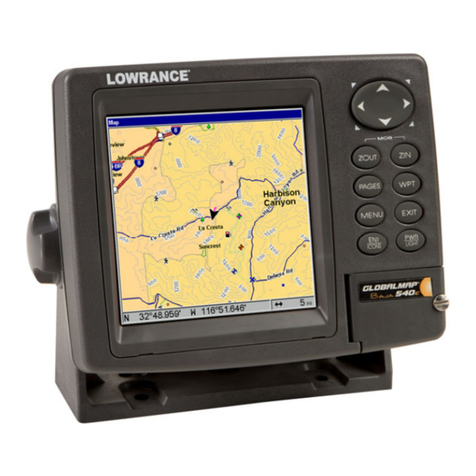
Kongsberg SIMRAD CP40 User manual

Simrad CP40/50
DGPS Chartplotter
183.0200.702 English
00383.21
Note!
Insert or remove C-MAP cartridges ONLY through CHART menu or when unit is off.
All electronic navigation equipment is subject to external factors beyond the control of the
manufacturer. Therefore such equipment must be regarded as an aid to navigation. The
prudent navigator will, for that reason, never rely on a single source for position fixing and
navigation.

MOB ‘MAN OVERBOARD’ function
MOB In case someone falls overboard, press the [MOB] key and hold
for two seconds (or activate an external MOB switch), and the system
will provide all relevant data for an efficient rescue operation.
Press [CLR] to confirm and reset the alarm.
Display 1
Display 3
Display 2
Screen layout default after activating
MOB.
Display 1: The MOB display will provide the position where the man
fell overboard, together with present course (C), bearing (B), and
distance (DIST) to the MOB position.
Elapsed time - first in seconds and then in minutes. If “*” is shown
instead of number of minutes, means that the elapsed time has
exceeded 9999 minutes.
Display 2: The position display will provide date, time and present
position.
Display 3: The CHART display will provide a graphical impression of
a man floating in the water at the MOB position together with a course
line to follow to return to the incident.
MENU Call up the menu bar, and…
4,2 Press [4], and [2], to turn the MOB function off
MENU Call up the menu bar, and…
2,6 Press [2], and [6], to re-call the last MOB position

CP40/50 DGPS Chartplotter Table of contents
1. Introduction and system
familiarization
1.1 Introduction and system
familiarization, 5
1.2 Safety summary, 6
2. Fundamentals & initial start-up
2.1 Fundamentals of the PAGE and
WINdow system, 7
2.2 Key functions, 10
2.3 Menu bar, 12
2.4 Menu layout, 13
2.5 Choice of symbols, 14
2.6 Naming of routes, points, etc., 14
2.7 Initial start-up, 15
2.8 Turn power off, 16
3. Chart menus and
INFO windows
3.1 Chart menu, 17
3.1.1 Charts, 17
3.2 C-MAP cartridges, 20
3.3 INFO windows, 22
3.3.1 Cursor inactive, 22
3.3.2 Cursor not placed on object
or user data, 23
3.3.3 Cursor placed on waypoint, 24
3.3.4 Cursor placed on route leg
or line leg, 25
3.3.5 Cursor placed on routepoint
or linepoint, 26
3.3.6 Cursor placed on trackpoint, 27
3.3.7 Cursor placed on target, 28
3.3.8 GOTO function, 29
3.3.9 PLOT function, 30
3.4 Chart setup, 32
4. Position menus
4.1 Position display, 35
4.2 Set & drift, 39
4.3 Speed diagram, 40
4.4 Dual speed display, 41
4.5 Wind display, 42
4.6 MOB position, 44
4.7 Satellite status, 45
4.8 DGPS setup, 47
4.9 DSC alarm, 49
5. Waypoint / route menus
5.1 WP list, 51
5.2 Routes stored in the memory, 52
5.3 Route calculation, 54
5.4 Lines stored in the memory, 55
5.5 Start / stop track, 56
5.6 Tracks stored in the memory, 58
5.7 Targets stored in the memory, 59
5.8 Data transfer via DataCard, 60
6. Navigation menus
6.1 NAV menu (NAV inactive), 63
6.1.1 - Navigation display, 63
6.2 NAV menu – (NAV active), 65
6.2.1 - Navigation display, 66
6.2.2 - Navigation setup, 67
6.2.3 – Turn NAV off, 67
6.2.4 – ETA & AVN, 67
6.2.5 – Set & drift trim display, 69
6.2.6 – Waypoint advance, 69
6.3 Anchor guard, 70
6.4 MOB navigation, 71
6.5 Navigation examples, 71
6.5.1 Chart/cursor navigation, 72
6.5.2 Waypoint navigation, 73
6.5.3 Route navigation, 74
6.5.4 Track navigation, 77

CP40/50 DGPS Chartplotter Table of contents
7. ECHO and SPECIAL menus
7. Echo menu, 81
7.1 Depth & temperature diagram, 81
7.2 Special menu, 83
7.2.1 Speed alarm, units & language, 83
7.2.2 Interface setup, NMEA, 85
7.2.3 Interface setup, alarm/log, 89
7.2.4 Decca lanes, 90
7.2.5 Loran C, 91
7.2.6 Display color, 92
7.2.7 Factory settings, 93
8. Installation and service
8.1 Installation of CP40, 95
8.2 Installation of CP50, 97
8.3 Place of installation of
display unit, 99
8.4 Installation of DS40/50, 99
8.4.1 Operation of DS40/50, 100
8.5 Installation of antenna, 101
8.6 Electrical connections, 102
8.6.1 Power supply connections, 103
8.6.2 Fuse, 103
8.6.3 NMEA0183 interface conn., 103
8.7 Optional connections, 104
8.8 Preventive maintenance, 105
8.9 Repair and service, 106
8.10 Troubleshooting, 107
8.11 Specifications, 108
Appendix A
Glossary of terms, 111
Appendix B
List of datums, 115
Appendix C
C-MAP attributes, 117
Index, 123
CE Declaration, 127
International warranty, 129
List of Simrad distributors

CP40/50 Introduction and safety summary Chapter 1
5
1.1 Introduction and system familiarization
Congratulations on your purchase of SIMRAD CP40/50 DGPS Chart-
plotter. Great care has been taken to create this innovative navigation aid
… both in design and performance. The CP40/50 is a combination of the
latest GPS receiver technology and built-in differential receiver for
accurate positioning plus detailed cartography; all in a unique slim-line
design with a 10” (CP40) or 14” (CP50) large LCD display in TFT color.
The CP40/50 chart system includes a built-in world chart for rough
planning and overview. The choice of chart system best suitable for the
CP40/50 was carefully singled out to be the C-MAP NT mini cards. The
optional C-MAP charts are available world-wide at your local Simrad
dealer.
The Global Positioning System is at this time and age the most common
system used for navigation and positioning all over the world. Not only for
maritime use, but also for land-based applications and aviation.
The satellite-based system has been developed and is operated by the US
Department of Defense in order to provide an accurate and reliable
service, which include a 24-hour global coverage.
The GPS system consists of approx. 24 satellites which orbit around the
Earth at an altitude of approx. 20,200 km. The satellites transmit perfectly
synchronized data. However, depending on the position, the signals will
reach the receiver at a slightly different time. By adding the measured time
difference to the known position of the satellites it is possible to calculate
the ship’s position to within a few meters.
DS40/50 Dual Station for the CP40 is available in black & white or in
TFT color, and for the CP50 in TFT color only.
How to use this manual?
It is a good idea if you make yourself familiar with the key functions,
menu structure and rotation of pages (screens) described in chapter 2
before you start out, and then proceed with section 2.7 Initial start-up.
For quick location of a certain term, please check the ”Glossary of terms”
and the ”Index” at the back of the manual.

CP40/50 Introduction and safety summary Chapter 1
6
How to interpret special marked key symbols, etc. in the manual:
+/- Either the + (plus) or – (minus) key may be applied.
0-9 Alpha-numeric keys for insertion of figures.
A-Z Alpha-numeric keys for insertion of letters.
FEmphasizes important points.
1,3 Indicates that you should press the keys [1] and [3] to obtain what is
written in italic next to the keys.
1.2 Safety summary
Precaution The operating unit should not be exposed to direct sunlight, as
“boiling” the display may cause too high temperatures internally and
subsequently damage parts of the unit beyond repair.
Quality service personnel The CP40/50 is sealed and does not contain any
user serviceable parts. Opening of the unit will void its warranty. Touching
electrical parts inside may cause bodily harm or death. If the unit is not
working properly, please check section 8.10 Troubleshooting. If your
CP40/50 requires servicing or repair, call your authorized SIMRAD dealer.
Power source, fuse and power cable Check that the DC power supplied to
the unit is within the range of 10 to 32 volts. Note that the appropriate fuse
must be employed (see the fuse rating in section 8.11 Specifications. Ensure
that the power cord is firmly attached.
Grounding The CP40/50 is a sophisticated piece of electronic equipment.
To reduce electrical interference and risk of electrical shock, properly
ground the unit to the ship’s ground using the ground screw on the back of
the unit.
Default settings All user implemented data in the CP40/50 can be erased
by making a reset of the unit and thus return to factory default settings.

CP40/50 Fundamentals & initial start-up Chapter 2
7
2.1 Fundamentals of the PAGE and WINdow system
The CP40/50 DGPS Chartplotter has a multi-function screen data
presentation system. You can choose to have a full screen, or a screen
divided into e.g. a chart display and two data/chart displays, etc.
The display which is currently activated is indicated by a highlighted
frame around the active window. There are five screen combinations to
choose from:
1 2
WINdow 0 4 3 5 6
1. Full (1/1) screen. 2. Four ¼ displays. 3. Two ½ displays.
1 2
46 5 3
4. & 5. Combination displays of one ½ and two ¼ displays shown
together in the same screen.
FNot all displays are available in WINdows 5 and 6.

CP40/50 Fundamentals & initial start-up Chapter 2
8
As many as 4 screen combinations or full
screens can be saved in 4 pages (layers).
Press the [PAGE] key to toggle between the 4
pages, or hold the [PAGE] key depressed for
two seconds to start a rotation of the 4 pages.
Press [PAGE] again to return to manual
operation.
To mix and match the various chart and data displays you wish to have
in the PAGE and WINdows presentation, you will first need to know
what is pre-set from the factory:
PAGE Scroll through the four pre-set pages to see if you wish to exchange
any of the displays with a different one.
Example of how to edit a pre-set page:
window
5
window
2
window
3
We pretend that in this page, window 2 contains the
navigation display (highway), window 3 a chart
display in a large scale for overview, and window 5
a chart display in a smaller scale to enlarge a
certain area.
You now wish to insert the Position display in window 3 instead of the
chart display. This is the procedure:
WIN Press the [WIN] key until the frame around window 3 is highlighted
MENU Call up the menu bar, and…
2,1 then call up the POS menu and select “Position”
- you will now have the Position display in window 3 instead of the
chart display.
Example of how to edit a full screen to four ¼ displays:
We pretend that you are looking at a full screen which you wish to
divide into four ¼ displays. This is the procedure:
MENU First call up the menu bar, and…
2then call up the POS menu - see example next page.

CP40/50 Fundamentals & initial start-up Chapter 2
9
POSITION WIN
_2_
POS
_1_Position
_2_Set & drift
_3_Speed diagram, etc. …
What you do now will determine which
WINdow the display you are about to
select will appear in.
Press the [WIN] key repeatedly to scroll
through the window system.
WIN Press the [WIN] key once to select WINdow 1
-which is the left top quarter of the screen.
1Select the Position display
- you will now have the position display presented in window 1.
The rest of the windows in this page i.e. window 2, 3 and 4 will contain
the displays which were pre-set from the factory. They can all be
exchanged with new displays at your choice.
FHowever, the same display can not appear twice on the same page,
so in case you are trying to select the same display in a second
window, this is what will happen:
As per above example, you have selected the Position display in
window 1, but it may just happen that the Position display was pre-set
to window 2 – therefore window 2 will now show the legend: “ Select
display via MENU.”
You may select the same display to appear on different pages, but not
on the same page.

CP40/50 Fundamentals & initial start-up Chapter 2
10
2.2 Key functions
A description of the key functions is available at the start-up display in
the Quick guide. Some of the key functions are general and can be
applied at any time, other key functions are related to a certain menu(s)
and can only be applied when in the appropriate menu.
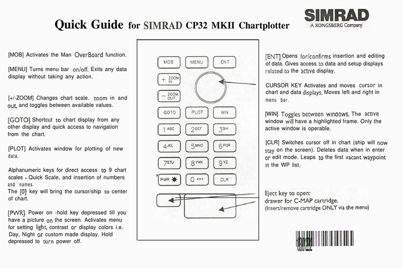
WIN Toggles between windows. The active window will have a highlighted
frame. Only activated windows are operable.
PAGE Toggles between four pre-selected pages (screens). Hold two seconds
for automatic rotation of pre-selected pages. A new, single press on
[PAGE] will return to normal operation.
MENU Turns the menu bar on/off. Exits any data display without taking any
action.
ENT Opens for/confirms insertion and editing of data. Calls up information
on marks, waypoints, etc. on chart together with several INFO
windows from a chart display. Gives access to setup displays.
Moves cursor in data displays and charts + activates cursor on chart.
Moves left and right in the menu bar.
CLR Turns cursor off in chart display. Deletes data in enter or edit mode.
PWR-Calls up a window where you can adjust the lighting in the screen,
background light in keypad, and select Daylight display, Night display
or custom made display. Hold two seconds to turn the power off.
MOB Hold two seconds to activate the MOB – “Man overboard” function,
which starts a track and provides guidance back to the MOB position.
ZOOM
+ IN Zooms in for greater chart details (smaller scale) / zooms out for better
ZOOM
- OUT overview (larger scale). + and –toggles between available values.

CP40/50 Fundamentals & initial start-up Chapter 2
11
1-9
A-Z The alpha-numeric keys inserts and selects data in data displays.
Keys 1-9 are also Quick scales i.e. selects fixed chart scales, and key 0
will center the cursor/ship on the chart.
CHART
GOTO Hotkey to Chart 1 i.e. jumps to window on the screen with Chart 1
display; if none: inserts Chart 1 in active window.
Activates INFO window with choice of navigation modes.
PLOT Plots down the actual ship/cursor position on chart. Activates INFO
window with the possibility of plotting a waypoint, route, line, etc.
POS Hotkey to Position display i.e. jumps to window on the screen with
Position display; if none: inserts Position display in active window,
except for Window 5 and 6, which are ½ screen sizes.
NAV Hotkey to Navigation display i.e. jumps to window on the screen with
Navigation display; if none: inserts Navigation display in active
window, except for Window 5 and 6, which are ½ screen sizes.
WP Hotkey to WP list i.e. jumps to window on the screen with WP list;
if none: inserts WP list in active window.
ROUTE Hotkey to Route list i.e. jumps to window on the screen with Route
list; if none: inserts Route list in active window.
TRACK Direct access to ‘Start track’ function.

CP40/50 Fundamentals & initial start-up Chapter 2
12
2.3 Menu bar
MENU Toggles the menu bar on/off
To fit in the complete menu bar across the screen, some of the menus
have been abbreviated. However, the last selected menu will be
highlighted, and if it’s an abbreviation of the menu, then the complete
menu title is written above the menu bar e.g.:
NAVIGATION WIN
_1_
CHART
_2_
POS
_3_
WP/RTE
_4_
NAV
_5_
ECHO
_6_
SPECIAL
_1_Navigation
_2_WP, etc. …
Having selected e.g. 4:NAVIGATION from the menu bar, its associated
menus will drop down. Key in the number next to the function you
wish to call forward, or use the cursor key to highlight the function and
press [ENT].
If you want to switch to a different menu, use the cursor key to move to
the adjacent menu.
Most functions in the menus are general, and can be called forward at
any time, but a few are related to a certain menu(s) and can only be
called forward or activated in the appropriate menu. Inactive functions
in the menu will have a different color from the rest of the functions.
Which window is active (see top line of the menu to the right) can also
have something to do with what functions are available. Use the [WIN]
key to toggle between active windows and keep an eye on the functions
in the menu to see how they may change color.
The menu bar will disappear from the screen at the selection of a
function, or by pressing the [MENU] key. Besides, if not used, it
automatically turns off after 30 seconds.

CP40/50 Fundamentals & initial start-up Chapter 2
13
2.4 Menu layout
_1_
CHART
_2_
POS
_3_
WP/RTE
_1_Chart 1 1:26400000 _1_Position _1_WP list
_2_Chart 2 1:6600000 _2_Set & drift _2_Routes
_3_C-MAP cartridges _3_Speed diagram _3_Route calculation
_4_Dual speed _4_Lines
_5_Wind _5_Start track
_6_MOB position _6_Tracks
_7_Satellites _7_Targets
_8_DGPS _8_Data transfer
_9_DSC alarm
_4_
NAV*
_5_
ECHO
_6_
SPECIAL
_1_Navigation _1_Depth & temperature diagram _1_Speed alarm, units & language
_2_WP _2_NMEA interface
_3_ROUTE _3_Alarm/log output
_4_TRACK _4_Decca lanes
_5_ANCHOR _5_Loran C
_6_Display color
_7_Factory settings
_4_
NAV**
_1_Navigation
_2_Turn NAV off
_3_ETA & AVN
_4_Set & drift trim
_5_WP advance
The NAV menu is dynamic and will adapt to the function
which is currently active.
* No Navigation mode is activated.
** One of the Navigation modes is activated.

CP40/50 Fundamentals & initial start-up Chapter 2
14
2.5 Choice of symbols
Waypoints and other points appearing on the screen can be marked by
one of 18 symbols:
2.6 Naming of routes, points, etc.
First select the key with the desired letter, then you can either repeat
the keystrokes, which will toggle between e.g. A,B,C,1, or once you
have selected one letter you can go back and forth in the alphabet by
means of the +/- keys. Use the cursor key to go to next space or to go
back one space if you make a mistake.
Depending on the selected language the 0 (zero) key will hold special
characters e.g. Æ Ø Å Ä Ö Ü Ñ, and the 9 (nine) key will hold: (empty
space) . -
Press the [CLR] key to delete everything from cursor position and to the
right of cursor on that row.
Waypoint
Red buoy
Green buoy
Wreck
Danger
Beacon
Fish
Platform
Rock awash
Harbour
Marker
North
South
East
West
Starboard
Port
MOB

CP40/50 Fundamentals & initial start-up Chapter 2
15
2.7 Initial start-up
PWR-To turn on the power, press and hold the [PWR] key till a picture
appears on the screen
PAGE Press [PAGE] to scroll through a quick guide which informs of the use
of the keys and where you can enter owner’s setup
ENT Press [ENT] when ready to assume normal operation
PWR-Press [PWR] again to adjust the lighting in the screen and select day or
night display, etc., move around in display by means of the cursor key
and change settings with +/- keys, and…
ENT Confirm with [ENT]
The unit will now perform a fully automatic start-up and find the cor-
rect position without further data entries. The start-up phase is com-
pleted when a position appears in the position display – see section 4.1.
Select display language:
MENU Call up the menu bar, and…
6,1 press [6] and [1] to call up the language display
Go to the bottom line in the display
+/- Select language
ENT Confirm entry

CP40/50 Fundamentals & initial start-up Chapter 2
16
2.8 Turn power off
PWR-Call up INFO window, and…
PWR-Press and hold until screen turns black
The CP40/50 is now turned off. All data and setups are saved and
stored in the internal memory and, of course, will be available next
time the unit is turned on.

CP40/50 Chart menus and INFO windows Chapter 3
17
3.1 Chart menu
_1_
CHART
_1_Chart 1 1:26400000 - see section 3.1.1.
_2_Chart 2 1:6600000 - see section 3.1.1.
_3_C-MAP cartridges - see section 3.2.
FFor safety reasons, navigation with electronic charts should always
be combined with authorized paper charts.
3.1.1 Charts
It is possible to have two charts in different scales on the screen at the
same time. Each chart can be operated individually, and each will have
it’s own cursor and individual chart setup.
MENU Call up the menu bar, and…
WIN select the WINdow in which the large-scale chart should appear, and…
1,1 press [1] and [1] to call up Chart 1in scale 1:26400000
MENU Call up the menu bar, and…
WIN select the WINdow in which the detailed chart should appear, and…
1,2 press [1] and [2] to call up Chart 2 in scale 1:6600000
The chart display opens for the built-in world chart, as well as the
optional, detailed C-MAP electronic charts (C-MAP cart must be
inserted in the drawers below the CP40/50’s keypad).
FShortcut feature:
CHART
GOTO Hotkey to Chart 1 i.e. jumps to window on the screen with Chart 1
display; if none: inserts Chart 1 in active window.

CP40/50 Chart menus and INFO windows Chapter 3
18
d 231° 16.3kn 26°46.020N 56°29.107W
Cat Fish Bay
The top line of the chart display (with cursor off) will give you ship’s
position, speed, course and status of differential data – refer to section
4.1 Status indicator and accuracy.
With cursor on, the top line will show the cursor position in lat/long,
bearing and distance from actual position to cursor position.
The ship symbol indicates the present position on the chart and the
pointer informs of the actual true course (course over ground). There is
a built-in autohome function which automatically moves the chart to
maintain the ship symbol in the display (with cursor off).
FPress [ENT], [0] to center the ship on the chart.
Cursor function
With chart display active, press the cursor key to activate the cursor
and…
CLR Press [CLR] to turn the cursor off.
Use the cursor key to move cursor in any direction on the screen – the
chart will automatically adjust when cursor reaches the edge of the
screen.
FPress [ENT], [0] to center the cursor on the chart.
Chart
scale
indicator
can be set
ON/OFF
in “Chart
setup”.

CP40/50 Chart menus and INFO windows Chapter 3
19
In data displays the cursor will be shown in form of a ruling box
around the active field.
Zoom function – with cursor on, the zoom function will zoom around
the cursor. With cursor off, the zoom function will zoom around the
ship´s position.
ZOOM
+ IN Zoom in for details (smaller scale)
ZOOM
- OUT Zoom out for overview (greater scale)
1-9 FUse one of the shortcut keys to quickly change the chart scale:
Press [1] = 1:6.600.000,
[4] = 1:200.000,
[7] = 1:6.000,
[2] = 1:2.000.000,
[5] = 1:60.000,
[8] = 1:2.000,
[3] = 1:600.000,
[6] = 1:20.000,
[9] = 1:600
Chart details may not be available in all scales in all areas. Non-
covered areas will be marked as hatched or all blue with coordinate
grid (with grid set to AUTO in chart setup), depending on the actual
scale.
The built-in world chart can be zoomed up/down in six steps from a
scale of approx. 1:33,000,000 to 1:2,000,000.
An over-zoom function enables you to zoom beyond the chart, which
automatically is switched off and replaced by a lat/long coordinate
grid. In this mode the scale can go down to 1:600.

CP40/50 Chart menus and INFO windows Chapter 3
20
3.2 C-MAP cartridges
On the front of the CP40/50 below the keypad are two small watertight
drawers wherein you place the C-MAP cartridge(s) you wish to load.
FDo not attempt to insert or remove cartridges unless the CP40/50 is
turned off, or chart reading is in stand-by:
MENU Press [MENU], [1] and [3] to load pop-up window for insertion/removal
1,3 of C-MAP cartridge(s)
Example:
C-MAP cartridges
UPPER
Name: P&T: MELBOURNE BEACH TO LAKE WORTH INL
Code: NA-B502.02
Date: 13/11/1998
LOWER
Name: DENMARK NORTH COAST & LIMFJORDEN
Code: EN-B102.03
Date: 01/03/1999
Chart
reading is
now in
stand-by, and
you may
insert/
remove
cartridges.
MENU Exit Test ENT
To open the drawer below the keypad, press the eject key next to the
drawer. Place the cartridge in the tray with the terminals pointing
towards the unit, and push the drawer back in place – it has to make a
“click” sound to be closed tight and remain watertight.
ENT Press [ENT] to test what is on the C-MAP cartridge which you have
just placed in one of the drawers
The CP40/50 will now test the data on the cartridge(s) to see if its valid
and free from faults.
FIf a cartridge is defect, it must be removed before you can exit the
display.
This manual suits for next models
1
Table of contents
Other Kongsberg GPS manuals
