Konica Minolta MK-734 User manual

E-1
MK-734 Power Supply BOX
INSTALLATION MANUAL
A4NJ-9550-04
Applied Machines: C658/C558/C458/C368/C308/C258/C554e/C454e/C364e/C284e/C224e/C554/C454/C364/
C284/C224/C287/C227/554e/454e/364e/284e/224e/367/287/227
COLOR MFP: 65 ppm/55 ppm/45 ppm/36 ppm/30 ppm/28 ppm/25 ppm/22 ppm
MFP: 55 ppm/45 ppm/36 ppm/28 ppm/22 ppm
Product Code: A79J/A79K/A79M/A7PU/A7PY/A7R0/A5AY/A5C0/A5C1/A5C2/A5C4/A2XK/A4FJ/A161/A4FK/A4FM/
A797/A798/A61D/A61E/A61F/A61G/A61H/A789/A7AH/A7AK
1. Accessory parts *1 Use the power cord appropriate for the region
where the machine is used.
*2 Depending on the marketing area, this power
cord may not be included.
*3 This part is not used in this installation.
Note:
• This manual provides the illustrations of the
accessory parts and machine that may be
slightly different in shape from yours. In that
case, instead of the illustrations, use the
appearance of your machine to follow the
installation procedure. This does not cause any
significant change or problem with the proce-
dure.
• If none of the later steps instruct you to use the
parts including screw and cover that you
removed following the instructions described in
this manual, discard them.
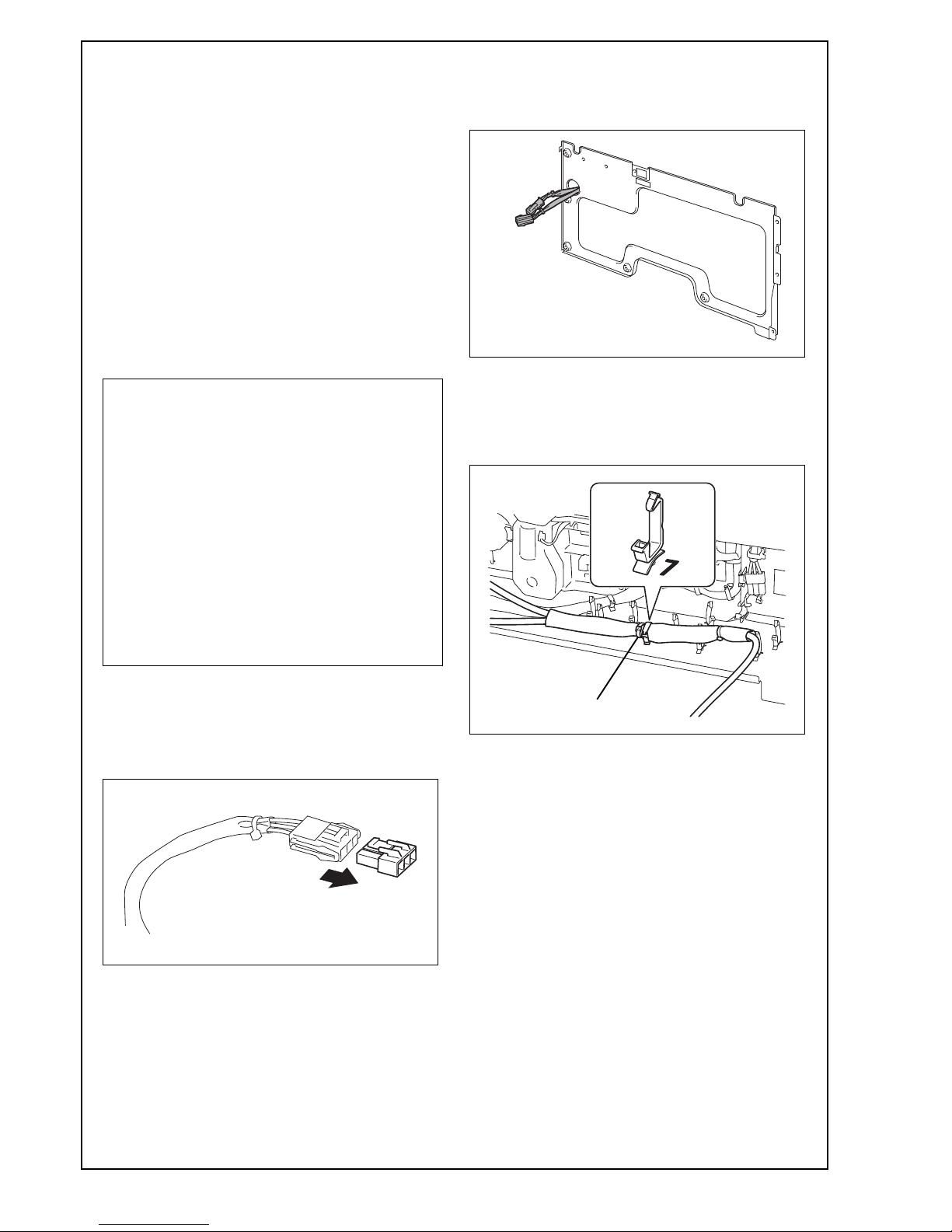
• To distinguish the supplied power cord A (for
North America) and power cord B (for Taiwan),
use the method described below.
Power cord A: The label is attached to the
cord.
Power cord B: The pins of the plug has the
cover.
No. Name Shape Q’ty
1. Power supply
Box
1
2. Power cord A
(for North
America) *1*2 1
3. Power cord B
(for Taiwan)
*1*2 1
4. Power cord C
(for Europe)
*1*2 1
5. Power cord D
(for China) *1*2
1
6. Screw A
(3 x 12 mm) 3
7. Screw B
(4 x 12 mm) *3 1
8. Installation
manual 1
set
Keep this bag away from babies and
children. Do not use in cribs, beds,
carriages, or playpens.
The thin film may cling to nose and
mouth and prevent breathing. This bag is
not a toy.
Power cord A Power cord B
Label Cover

E-2
Note:
<C658/C558/C458/C368/C308/C258/C554e/C454e/
C364e/C284e/C224e/C554/C454/C364/C284/C224/
554e/454e/364e/284e/224e>
• To install the Power Supply BOX MK-734, the
Heater HT-509 or the Transformer kit TK-101 is
required.
<C287/C227/367/287/227>
• To install the Power Supply BOX MK-734, the
Heater HT-509 is required.
2. Installation procedures
Note:
To install this option or the related option, perform
the procedures described below.
(1) Remove the connector cover from the power
cable of the power supply Box.
Note:
Remove the cover for the indicated connector (3
pins) only.
<C287/C227/367/287/227 only>
(2) Route the power supply Box cable through the
slot in the previously removed rear cover for the
Paper Feed Cabinet or the Desk.
(3) Route the power cable through the wire saddle
with mark “7.”
Note:
Fixate the right side of the red cable tie immedi-
ately, as shown in the illustration.
<When use this option only with the heater or install
this option on models C287/C227/367/287/227>
→Perform the procedures in this chapter after
installing the Heater referring to its installation
manual.
<When the Transformer kit is used alone>
→Refer to the installation manual of the Trans-
former kit.
<When the Heater and the Transformer kit are
installed at the same time>
→Perform the procedures up to the step (6) in
this chapter after installing the Heater referring
to its installation manual, and then refer to the
installation manual of the Transformer kit.
Cable tie

E-3
(4) Connect the connector of the power cable to the
connector of the heater.
Note:
For the Paper Feed Cabinet PC-415/PC-414/PC-
413/PC-410, the connected connectors must be
within the space between the plate and the har-
ness shown in the illustration.
(5) Route the power cable through the eight wire
saddles and the edge cover.
Note:
• The routing order must be from the wire saddle
nearest to the connectors to farthest.
• There should be no slack in the cable between
the connector and the wire saddle nearest to it.
(6) Route the power cable through the two wire sad-
dles.
Note:
<C658/C558/C458/C368/C308/C258/C554e/C454e/
C364e/C284e/C224e/C554/C454/C364/C284/C224/
554e/454e/364e/284e/224e only>
When the Transformer kit is installed at the same
time, for the following information refer to the
installation manual of the Transformer kit.
(7) Pass the indicated connector through the wire
saddle.
Note:
The connector must be in the orientation shown in
the illustration.
< OK > < NG >

E-4
<C658/C558/C458/C368/C308/C258/C554e/C454e/
C364e/C284e/C224e/C554/C454/C364/C284/C224/
554e/454e/364e/284e/224e>
(8) Attach the rear cover of the Paper Feed Cabinet
or the Desk. (Five screws)
Note:
• Route the power cable through the notch
located at the upper right side of the rear cover.
• Tighten the indicated screw ➀first, then the
screw ➁, and then other three screws.
<C287/C227/367/287/227>
(8) Attach the rear cover of the Paper Feed Cabinet
or the Desk.
C287/C227: Eight screws
367/287/227: Nine screws
Note:
Tighten the indicated screw ➀first, then the screw
➁, and then other seven screws.
<C287/C227>
<367/287/227>
<C287/C227/367/287/227 only>
(9) Reinstall the rear right cover. (Two screws)
(10) Attach the mounting plate to the machine with
supplied two screws A.
Note:
Tighten the indicated screw ➀first, then screw ➁.
➁
➀
➁
➀

E-5
(11) Route the power cable through the wire saddle
of the mounting plate.
(12) Insert the screw A into the indicated hole on the
mounting plate and tighten it.
(13) Attach the power supply Box to the mounting
plate.
Note:
Slide it after first clipping tab ➀located on the right
side, and then clip tab ➁on the left side.
(14) Connect the supplied power cord to the power
supply Box.
Note:
Use the power cord appropriate for the region
where the machine is used.
(15) Insert the power plug of the main body and the
power plug of the power supply Box into a wall
outlet.
(16) Turn ON the power switch of the main body.
(17) Turn ON the power supply Box.
➁➀
Use the appropriate power cord.
Failure to do this could result in a fire or
electrical shock.

E-6
POWER CORD INSTRUCTION
The installation of (or exchange to) a power plug which fits to the wall outlet of the installation location shall be
conducted in accordance with the following:
The wires in the power supply cord shall be connected to the terminals of the plug in accordance with the fol-
lowing:
Color of the wire Terminal of the plug
Brown Black →Marked with “L” or “W” or colored RED
Light Blue White →Marked with “N” or colored BLACK
Green-and-Yellow →Marked with “E”, “PE” or “ ” or colored
GREEN or GREEN-AND-YELLOW
Configuration Standard Rating Usually
found in Configuration Standard Rating Usually
found in
IEC60884-1
CEE7/7
10A
250V
European
countries
NEMA
5-15P
15A
125V
US
Canada
Saudi Arabia
KSC8305 10A
250V
Korea CNS10917
CNS690
15A
110V
Ta i w a n
CEI23-16/7 10A
250V
Italy SABS164-1
(BS 546A)
15A
250V
India
South Africa
SEV 1011 10A
250V
Switzerland SI 32 10A
250V
Israel
DEMKO
107-2-D1
10A
250V
Denmark AS/
NZS3112
NZ SS 198
10A
250V
Australia
New Zealand
BS 1363 13A
250V
UK/
Hong Kong
GB2099.1
GB1002
10A
250V
China
SS145 13A
250V
Singapore IRAM 2073 10A
250V
Argentina
SASO444
(BS1363)
13A
250V
Saudi Arabia NBR14136 20A
250V
Brazil
• Select power plug which meets the following criteria
- The plug has voltage and current rating appropriate for the product’s rating marked
on its name plate.
- The plug meets regulatory requirements for the area.
- The plug is provided with grounding pin/terminal.
• In case the wall outlet of the location does not fit to the appropriate plug for the product,
require the customer for installation of an appropriate outlet.
Table of contents